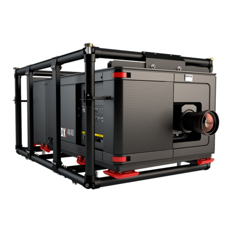
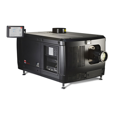
Barco DP2K-12C User manual

DP2K-12C/11CX
Service manual
R5905043/15
19/02/2018

Registered address: Barco NV
President Kennedypark 35, 8500 Kortrijk, Belgium
Phone: +32 56.23.32.11
Fax: +32 56.26.22.62
Support: www.barco.com/en/support
Visit us at the web: www.barco.com
Barco NV
Beneluxpark 21, 8500 Kortrijk, Belgium
Phone: +32 56.23.32.11
Fax: +32 56.26.22.62
Support: www.barco.com/en/support
Visit us at the web: www.barco.com
Printed in Belgium

Copyright ©
All rights reserved. No part of this document may be copied, reproduced or translated. It shall not otherwise be recorded, transmitted or
stored in a retrieval system without the prior written consent of Barco.
Trademarks
Brand and product names mentioned in this manual may be trademarks, registered trademarks or copyrights of their respective holders.
All brand and product names mentioned in this manual serve as comments or examples and are not to be understood as advertising for
the products or their manufacturers.
Changes
Barco provides this manual ’as is’ without warranty of any kind, either expressed or implied, including but not limited to the implied war-
ranties or merchantability and fitness for a particular purpose. Barco may make improvements and/or changes to the product(s) and/or the
program(s) described in this publication at any time without notice.
This publication could contain technical inaccuracies or typographical errors. Changes are periodically made to the information in this
publication; these changes are incorporated in new editions of this publication.
The latest edition of Barco manuals can be downloaded from the Barco web site www.barco.com or from the secured Barco web site
https://www.barco.com/en/signin.


Table of contents
TABLE OF CONTENTS
1. Safety ................................................................................................................ 5
1.1 Safety Instructions.................................................................................................................... 6
2. General............................................................................................................... 9
2.1 Convention projector orientation ....................................................................................................10
2.2 Location of the main components of the projector ................................................................................. 11
2.3 About the Projector Status Light ....................................................................................................14
2.4 Projector block diagrams............................................................................................................15
2.5 Interconnection diagram.............................................................................................................17
2.6 Spare parts for DP2K-12C/11CX....................................................................................................18
3. Preventative maintenance actions .............................................................................19
3.1 Monthly maintenance actions .......................................................................................................20
3.2 Lamp change maintenance actions.................................................................................................21
3.3 Three monthly maintenance actions ................................................................................................22
3.4 Annually maintenance actions ......................................................................................................23
3.5 4 yearly maintenance actions .......................................................................................................26
4. Troubleshooting ........ .. .. .. .. .. .. .. .. .. ................................................ .. .. .. .. .. .. .. .. .. ....... 27
4.1 Troubleshooting checklist . . .........................................................................................................29
4.2 Log files..............................................................................................................................74
5. Removal and installation of projector covers................................................................77
5.1 Removal of the lamp cover..........................................................................................................78
5.2 Removal of the input cover..........................................................................................................79
5.3 Removal of the front cover ..........................................................................................................80
5.4 Removal of the side cover...........................................................................................................81
5.5 Removal of the rear cover...........................................................................................................82
5.6 Removal of the top cover............................................................................................................83
5.7 Open the sealed compartment ......................................................................................................85
5.8 Close the sealed compartment......................................................................................................86
5.9 Installation of the top cover..........................................................................................................87
5.10 Installation of the rear cover.........................................................................................................88
5.11 Installation of the side cover ........................................................................................................89
5.12 Installation of the front cover........................................................................................................ 90
5.13 Installation of the input cover........................................................................................................91
6. Lamps and lamp houses ............. ... .............. .. .. ........ .. .. ........ .. .. ........ .. .. .......... .. .. .....93
6.1 Introduction .......................................................................................................................... 94
6.2 Removal of the lamp house .........................................................................................................96
6.3 Removal of the xenon lamp .........................................................................................................98
6.4 Installation of the Xenon lamp......................................................................................................102
6.5 Installation of the lamp house ......................................................................................................108
6.6 Resetting the lamp parameters . . . .................................................................................................110
6.7 Realignment of the lamp in its reflector............................................................................................111
6.8 Replacement of the Lamp Info module . . . . . .......................................................................................113
6.9 Replacement of the UV blocker . . . .................................................................................................115
6.10 Replacement of the lamp reflector.................................................................................................118
6.11 Cleaning the Reflector of the Lamp House........................................................................................121
6.12 Cleaning the UV blocker of the Lamp House......................................................................................122
7. Cold mirror assembly........................................................................................... 123
7.1 Introduction .........................................................................................................................124
7.2 Removal of the cold mirror assembly..............................................................................................125
7.3 Replace the Cold Mirror............................................................................................................127
7.4 Installation of the cold mirror assembly . . . . . .......................................................................................129
7.5 Adjusting the cold mirror ...........................................................................................................131
7.6 Cleaning the Cold Mirror . . . ........................................................................................................133
8. Light processor assembly..................................................................................... 135
8.1 Introduction .........................................................................................................................136
8.2 Light processor diagnostic .........................................................................................................138
8.3 Remove light processor top cover .................................................................................................139
8.4 Electrical disconnection ............................................................................................................140
8.5 Light processor assembly removal.................................................................................................141
8.6 Preparing the new light processor assembly ......................................................................................142
8.7 Installation of the light processor assembly ...................................................................................... .144
8.8 Electrical connections ..............................................................................................................146
8.9 Mount light processor cover........................................................................................................147
8.10 Mount light processor assembly into the flight case...............................................................................148
8.11 Finalize the installation of the light processor assembly ..........................................................................150
8.12 Replacement of the Light Sensor Module . . .......................................................................................151
8.13 Replacement of the dowser (shutter) ..............................................................................................152
R5905043 DP2K-12C/11CX 19/02/2018 1

Table of contents
8.14 Replacing of the notch filter ........................................................................................................154
8.15 Adjusting the notch filter............................................................................................................156
8.16 Cleaning the Prism exit side .......................................................................................................158
9. Convergence..................................................................................................... 159
9.1 Convergence controls ..............................................................................................................160
9.2 Preparing the convergence adjustment. . . . . .......................................................................................162
9.3 Red on Blue convergence......................................................................................................... .163
9.4 Green on Blue convergence .......................................................................................................165
10. Integrator rod .................................................................................................... 167
10.1 Introduction .........................................................................................................................168
10.2 Rod diagnostic ......................................................................................................................169
10.3 Removal of the integrator rod ......................................................................................................170
10.4 Installation of a new integrator rod.................................................................................................173
10.5 Adjusting the integrator rod ........................................................................................................177
11. Lenses and Lens holder ....................................................................................... 179
11.1 Available lenses ....................................................................................................................180
11.2 Lens selection ......................................................................................................................181
11.3 Lens removal .......................................................................................................................182
11.4 Lens installation ....................................................................................................................183
11.5 Cleaning the lens . . . ................................................................................................................185
11.6 Remove the lens holder............................................................................................................186
11.7 Install the lens holder...............................................................................................................189
11.8 Scheimpflug adjustment............................................................................................................192
11.9 Replacement of the Vertical Shift stepper motor ..................................................................................196
11.10 Replacement of the Horizontal Shift stepper motor ...............................................................................198
11.11 First Placement of the Inner Dust Rubber .. .......................................................................................200
11.12 Replacement of the Inner Dust Rubber . . . . . .......................................................................................204
12. Card Cage......................................................................................................... 207
12.1 Fan controller board ................................................................................................................208
12.2 Integrated Cinema Processor (ICP) board . .......................................................................................209
12.3 HD-SDI board + link decryptor .....................................................................................................210
12.4 Cinema controller board............................................................................................................211
12.5 Removing a board in the card cage................................................................................................213
12.6 Inserting a board in the card cage .................................................................................................214
12.7 Replacement of the RTC battery of the ICP board ................................................................................215
12.8 Battery replacement on the Cinema Controller Board ............................................................................217
12.9 Removing the button unit...........................................................................................................219
12.10 Installation of the button unit .......................................................................................................222
12.11 Replacement of the Button module (first generation Keypad) ....................................................................223
12.12 Replacement of the Keypad (first generation Keypad). . ..........................................................................226
12.13 Replacement of the Keypad assembly (second generation Keypad). ............................................................230
12.14 Replacement of the signal back plane .............................................................................................231
12.15 Replacement of the Link Decryptor................................................................................................243
12.16 Authorization to clear security warning on the projector ..........................................................................245
12.17 Replacement of the Status Light...................................................................................................246
13. Software update via Communicator (DC update companion).......... .. .. .. .. .. .. .. .. .. .. ............. 247
13.1 Software upgrade, launch DC update companion.................................................................................248
13.2 Software upgrade, projector, ICMP or touch panel ................................................................................251
13.3 ICP software upgrade ..............................................................................................................255
13.4 Link decryptor software update . . . .................................................................................................258
13.5 Update logging......................................................................................................................260
14. Communicator touch panel.................................................................................... 261
14.1 Introduction .........................................................................................................................262
14.2 Installing the touch panel interface.................................................................................................264
14.3 Reposition the touch panel interface...............................................................................................266
15. Power input.................................................... .. .. .. .. .. .. .. .. .. .. .. .. ........................... 267
15.1 Introduction .........................................................................................................................268
15.2 Getting access to the Mains Input components . ..................................................................................269
15.3 Replacement of the mains ON/OFF switch. .......................................................................................271
15.4 Replacement of the mains input filter..............................................................................................273
15.5 Closing the Mains Input compartment .............................................................................................275
16. Switched mode power supply...................................................................... .. .. .. .. .. . 279
16.1 Diagnostic LEDs on the SMPS.....................................................................................................280
16.2 Replacement of the Switched Mode Power Supply ...............................................................................281
17. Lamp power supply .. .. .. .. .. .. .. .. .. .. .. .. .. .. .. .. .. .. .. .. .. .. .. .. .. .. .. .. .. .. .. .. .. .. .. .. .. .. .. .. .. .. .. .. .. .. . 283
17.1 Introduction .........................................................................................................................284
17.2 LPS diagnostic LED’s ..............................................................................................................285
17.3 Removal of the LPS module .......................................................................................................287
2R5905043 DP2K-12C/11CX 19/02/2018
Table of contents
17.4 Installation of the LPS module .....................................................................................................289
18. Lamp power supply (single module)... ................. .. .. .. .. .. ................. ................. .. .. .. .. . 291
18.1 LPS module diagnostic LED’s......................................................................................................292
18.2 Removal of the LPS module .......................................................................................................294
18.3 Installation of the LPS module .....................................................................................................296
18.4 Replacing a large frame LPS with a single module LPS ..........................................................................299
19. Start Pulse Generator........................................................................................... 303
19.1 Introduction .........................................................................................................................304
19.2 Troubleshooting.....................................................................................................................305
19.3 Removal of the Start Pulse Generator.............................................................................................306
19.4 Installation of the Start Pulse Generator . . . . .......................................................................................308
20. Fan replacement procedure................................................................................... 311
20.1 Card cage fans .....................................................................................................................312
20.2 SMPS compartment fans. . . ........................................................................................................314
20.3 Light processor compartment fan ..................................................................................................316
20.4 Lamp cathode fan . . ................................................................................................................319
20.5 Lamp anode fan ....................................................................................................................324
20.6 Cold mirror fan......................................................................................................................327
20.7 Lamp Info Module fan ..............................................................................................................329
20.8 Integrated cinema processor fan...................................................................................................330
21. Maintenance procedures....................................................................................... 331
21.1 Cleaning the exterior of the projector ..............................................................................................332
21.2 Removing the front dust filter.......................................................................................................333
21.3 Clean the dust filter on the top side................................................................................................335
A. Pin configurations................................................................................................ 337
A.1 About General Purpose Inputs & Outputs (GPIO).................................................................................338
A.2 Pin configurations of the communication ports . ...................................................................................340
A.3 Pin configurations of the ICMP communication ports .............................................................................342
A.4 Pin configurations of the inputs . . . .................................................................................................345
B. Input formats ...................................................................................................... 347
B.1 Input formats. .......................................................................................................................349
Index.................................................................................................................... 351
R5905043 DP2K-12C/11CX 19/02/2018 3
Table of contents
4R5905043 DP2K-12C/11CX 19/02/2018
1. Safety
1. SAFETY
About this chapter
Read this chapter attentively. It contains important information to prevent personal injury while servicing the DP2K-12C/11CX pro-
jector. Furthermore, it includes several cautions to prevent damage to the DP2K-12C/11CX projector. Ensure that you understand
and follow all safety guidelines, safety instructions and warnings mentioned in this chapter before servicing the DP2K-12C/11CX
projector. After this chapter, additional “warnings” and “cautions” are given depending on the service procedure. Read and follow
these “warnings” and “cautions” as well.
WARNING:This manual is only intended for qualified service personnel.
Overview
• Safety Instructions
R5905043 DP2K-12C/11CX 19/02/2018 5
1. Safety
1.1 Safety Instructions
WARNING:Before removing/replacing any projector components, disconnect the power to the unit mains
terminals and unplug the power cord at UPS INLET.
Safety Instructions
1. Before returning an instrument to the customer, always make a safety check of the entire instrument, including, but not limited
to, the following items:
a) Be sure that no built-in protective devices are defective and/or have been defeated during servicing. (1) Protective shields
are provided on this chassis to protect both the technician and the customer. Correctly replace all missing protective shields,
including any removed for servicing convenience. (2) When reinstalling the chassis and/or other assembly in the cabinet,
be sure to put back in place all protective devices, including, but not limited to, insulating materials, barriers, covers/shields,
and isolation resistor/capacitor networks. Do not operate this instrument or permit it to be operated without all protective
devices correctly installed and functioning. Service people who defeat safety features or fail to perform safety checks may
be liable for any resulting damage.
b) Be sure that there are no cabinet openings through which an adult or child might be able to insert their fingers and contact a
hazardous voltage. Such openings include, but are not limited to, (1) excessively wide cabinet ventilation slots, and (2) an
improperly fitted and/or incorrectly secured cover panels.
c) Leakage Current Hot Check. With the instrument completely reassembled, plug the AC line cord directly into a 220 V AC
outlet (Do not use an isolation transformer during this test). Use a leakage current tester or a metering system that is
designed to comply with the new IEC, ANSI and UL standards. With the instrument AC switch first in the on position and
then in the off position, measure from a known earth ground (metal waterpipe, conduit, etc.) to all exposed metal parts
of the instrument (antennas, handle bracket, metal cabinet, screwheads, metallic overlays, control shafts, etc.). especially
any exposed metal parts that offer an electrical return path to the chassis. Any current measured must not exceed 3,5 mA.
Reverse the instrument power cord plug in the outlet and repeat test. ANY MEASUREMENTS NOT WITHIN THE LIMITS
SPECIFIED HEREIN INDICATE A POTENTIAL SHOCK HAZARD THAT MUST BE ELIMINATED BEFORE RETURNING
THE INSTRUMENT TO THE CUSTOMER OR BEFORE CONNECTING ACCESSORIES.
Leakage Current Tester
Reading should
not be above
3,5 mA
Test all exposed metal surfaces
Earth
Ground
+-
2-Wired cord
Also test with plug reversed
(Using AC Adapter plug as required)
AC Leakage Test
Device Under Test
Image 1-1
d) Ultraviolet Radiation exposure - Warning: This lamp can cause serious skin burn and eye inflammation from shortwave
ultraviolet radiation if not operated in enclosed fixtures. DO NOT operate this lamp in a fixture with a missing or broken lens
cover.
e) Ozone: Operating lamp generates ozone gas which is harmful to the respiratory system. Therefore the lamp should be
operated in adequately ventilated equipment.
2. Read and comply with all caution and safety-related notes on or inside the projector cabinet or on the projector chassis, or on
the picture tube.
3. Design Alteration Warning - Do not alter or add to the mechanical or electrical design of this apparatus. Design alterations and
additions, including, but not limited to, circuit modifications and the addition of items such as auxiliary audio and/or video output
connections, might alter the safety characteristics of this apparatus and create a hazard to the user. Any design alterations
or additions may void the manufacturer’s warranty and may make you, the servicer responsible for personal injury or property
damage resulting therefrom.
6R5905043 DP2K-12C/11CX 19/02/2018
1. Safety
4. Lamp explosion Protection Warning – The lamp in this projector operates with a high internal pressure and there is a slight risk
that the lamp may explode, particularly if it is used beyond its rated life. Do not remove, install, or otherwise handle the lamp
in any manner without first putting on shatterproof goggles equipped with side shields. People not so equipped must be kept
safely away while lamps are handled. Keep the lamp away from your body. For continued explosion protection, replace the
lamp only with one of the same type number. Always replace the lamp before the rated life time.
5. Hot Chassis Warning - This projector chassis has two ground systems: the primary ground system is formed by the negative
voltage of the rectified mains (power) and is only used as a reference in primary circuits; the secondary ground system is
connected to earth ground via the earth conductor in the mains (power) lead. Separation between primary and secondary
circuits is performed by the safety isolation transformers. Components bridging these transformers are also safety components
and must never be defeated or altercated. All user-accessible conductive parts must be connected to earth ground, or are kept
at SELV (Safety Extra Low Voltage).
6. Observe original lead dress. Always inspect in all areas for pinched, out-of-face, or frayed wiring. Do not change spacing
between components, and between components and the printed-circuit board. Check AC power cord for damage. Take extra
care to assure correct lead dress in the following areas:
a) near sharp edges
b) near thermally hot parts - be sure that leads and components do not touch thermally hot parts
c) the AC supply
d) high voltage
7. Components, parts, and/or wiring that appear to have overheated or are otherwise damaged should be replaced with compo-
nents, parts, or wiring that meet original specifications. Additionally, determine the cause of overheating and/or damage and, if
necessary, take corrective action to remove any potential safety hazard.
8. PRODUCT SAFETY NOTICE - Many electrical and mechanical parts have special safety-related characteristics some of which
are often not evident from visual inspection, nor can the protection they give necessarily be obtained by replacing them with
components rated for higher voltage, wattage, etc. Use of a substitute replacement that does not have the same safety charac-
teristics as the recommended replacement part in BARCO service data parts list might create shock, fire, and/or other hazards.
Product Safety is under review continuously and new instructions are issued whenever appropriate. For the latest information,
always consult the appropriate current BARCO service literature.
9. Do not spray chemical on or near this instrument or any of its assemblies.
10. Electrostatically Sensitive (ES) Devices Some semiconductor (solid state) devices can be damaged easily by static electricity.
Such components commonly are called Electrostatically Sensitive (ES) Devices. Examples of typical ES devices are integrated
circuits and some field-effect transistors and semiconductor "chip" components. The following techniques should be used to
help reduce the incidence of component damage caused by static electricity:
a) Immediately before handling any semiconductor-equipped assembly, drain off any electrostatic charge on your body by
touching a known earth ground. Wear a commercially available high impedance discharging wrist strap device.
b) After removing an electrical assembly equipped with ES devices, place the assembly on a static dissipative surface such as
a 3M No 8210 table mat, to prevent electrostatic charge buildup or exposure of the assembly.
c) Do not use freon-propelled chemicals. These can generate electrical charges sufficient to damage ES devices.
d) Do not remove a replacement ES device from its protective package until immediately before you are ready to install it
(Most replacement ES devices are packaged with leads electrically shorted together by conductive foam, aluminium foil or
comparable conductive material).
e) Immediately before removing the protective material from the leads of a replacement ES device, touch the protective material
to the chassis or circuit assembly into which the device will be installed. CAUTION: Be sure no power is applied to the chassis
or circuit, and observe all other safety precautions.
f) Minimize bodily motions when handling unpacked replacement ES devices (Otherwise harmless motion such as the brush-
ing together of your clothes fabric or the lifting of your foot from a carpeted floor can generate static electricity sufficient to
damage an ES device).
R5905043 DP2K-12C/11CX 19/02/2018 7
1. Safety
8R5905043 DP2K-12C/11CX 19/02/2018

2. General
2. GENERAL
About this chapter
This chapter contains some general information on projector level such as the location of the main components, internal wiring
diagram, spare parts list, etc.
Overview
• Convention projector orientation
• Location of the main components of the projector
• About the Projector Status Light
• Projector block diagrams
• Interconnection diagram
• Spare parts for DP2K-12C/11CX
R5905043 DP2K-12C/11CX 19/02/2018 9
2. General
2.1 Convention projector orientation
Convention
This manual refer to the left side of the projector as the side at your left hand when standing behind the projector and looking at the
projection screen in front of the projector.
L
BT
R
F
Image 2-1
T Top of the projector.
L Left side of the projector (Light Processor side).
F Front of the projector.
R Right side of the projector (Lamp side & Input side).
B Back side of the projector.
10 R5905043 DP2K-12C/11CX 19/02/2018

2. General
2.2 Location of the main components of the projector
Housing and air inlet filters
1
2
3
4
5
6
7
Image 2-2
1 Rear cover.
2 Top cover.
3 Left cover (Light Processor side).
4 Sealed compartment cover (Light processor side)
5 Lamp cover.
6 Input cover (Input & Communication unit).
7 Front cover.
R5905043 DP2K-12C/11CX 19/02/2018 11
2. General
Main internal components
11
8
9
12
10
13
14
15
16
17
18
20
19
Image 2-3
8 Lamp Power Supply (LPS)
9 Convergence cover plate
10 Backplane + light processor compartment fan
11 Lens holder assembly
12 Front dust filter (cleanable)
13 Button panel
14 Fan controller board
15 Integrated Cinema Processor board (ICP)
16 HDSDI board or Mediablock
17 Cinema controller board
18 Switched mode power supply board
19 Lamp house
12 R5905043 DP2K-12C/11CX 19/02/2018

2. General
20 Lamp info module fan
24
22
23
21
Image 2-4
21 Dust filter cold mirror
22 Light processor (assembly)
23 Light pipe
24 Anode fan assembly
25
24
26
27
Image 2-5
24 Anode fan assembly
25 Start pulse generator (SPG)
26 Cold mirror assembly
27 SPG cover plate
R5905043 DP2K-12C/11CX 19/02/2018 13
2. General
2.3 About the Projector Status Light
Overview
The projector status light can have 4 colors:
Flashing
green
Projector is booting up.
Green Projector is running normal.
Yellow Projector is running with warnings. Event can go on but a technical intervention will be necessary in the near
future to prevent a complete stop of the projector.
Red Projector is in error state. Problem could prevent normal operation. Solve the problem before continuing
with the projector.
Blue Projector runs in notification state. Maintenance action required. Lamp run time is exceeded. New lamp
must be installed.
14 R5905043 DP2K-12C/11CX 19/02/2018
2. General
2.4 Projector block diagrams
General block diagram
Signal backplane
Projector
ID
Cinema controller
Touch
Panel
Main
Input
Switched mode
Power Supply
Tail
light
Pump
Lamp power
supply
Start Pulse
Generator
Lamp info
Motor control
Button module
HDSDI input
TI decryptor
or
Mediablock
ICP
Fan controller
Motorized
Lens
3D controller
Light Sensor
Shutter
Red formatter
Green formatter
Blue formatter
Anode fan
Cathode fan
Fan2, 1-4
Fan1, 1-6
Lamp
Light processor
Electronic box
T
o UPS
From
UPS
Image 2-6
Communication block diagram
Signal backplane
Projector
ID
Cinema controller
Touch
Panel
Lamp power
supply
Start Pulse
Generator
Lamp info
Motor control
Button module
HDSDI input
TI decryptor
or
Mediablock
ICP
Fan controller
3D controller
Light Sensor
Red formatter
Green formatter
Blue formatter
Lamp
Light processor
Electronic box
RS232
IC
Ethernet
Image 2-7
R5905043 DP2K-12C/11CX 19/02/2018 15
2. General
• Any external command sent via Ethernet or serial will always be routed through the Cinema Controller to the Signal Backplane
and then on to the end device
• Cinema Controller contains a multi port internal Ethernet router, connected to all internal Ethernet devices.
• Once the Cinema Controller receives the command, it will convert it into the necessary protocol to control the end device.
• TI controls its own devices with commands to perform functions coming from the Cinema controller or from cinema server/IMe-
diablock.
• Decryption is handled by the Link decryptor or Mediablock.
• I²C communication between Fan Controller and Cinema Controller is used by the Fan Controller to send back error reporting
to Cinema Controller
• Cinema Controller receives error reporting and sends it to the Communicator and the log files.
Video block diagram
Signal backplane
Projector
ID
Cinema controller
HDSDI input
TI decryptor
or
Mediablock
ICP
Red formatter
Green formatter
Blue formatter
Light processor
Electronic box
Image 2-8
The following steps happen :
• If decryption link is present; video is sent from server via HDSDI cables to the projector HDSDI board (or PCI express cable if
media block is inserted).
• Video is decrypted on the Link decryptor board or Media Block and then sent to the Signal Backplane
• Video signal is sent to Integrated Cinema Processor
• ICP Board adds scaling, subtitle overlay, image cropping & applies all color correction. Also divides video signal into Red,
Green and Blue signals.
• Formatter applies any 3D frame rate multiplication if needed and turns signal into pulses to drive or cycle DMD mirrors.
• DMD’s are reflecting the light provided by the prism back to the prism and reflect it through the lens towards the screen.
16 R5905043 DP2K-12C/11CX 19/02/2018
Other manuals for DP2K-12C
3
This manual suits for next models
1
Table of contents
Other Barco Projector manuals

Barco
Barco R9002110 User manual

Barco
Barco DP2K-E series User guide

Barco
Barco NW-12 User manual

Barco
Barco UDM Series User manual

Barco
Barco HDF W22 Operating manual

Barco
Barco DATA 2100 R9001070 User manual

Barco
Barco R9002129 User manual

Barco
Barco R9840420 User manual

Barco
Barco R9010300 User manual

Barco
Barco FLM R20+ Performer User manual

Barco
Barco SIM 5W User manual

Barco
Barco F22 Series User manual

Barco
Barco iQ series User manual

Barco
Barco G50 User manual

Barco
Barco CLM HD8 Manual
Barco
Barco FS33 IR WUXGA User manual

Barco
Barco R9001890 User manual

Barco
Barco G50 User manual

Barco
Barco MCM-100S User manual

Barco
Barco R813307K User manual