Barco R7628162K User manual

BARCO PROJECTION SYSTEMS
Art. No. :
R5976124
Date :
29/05/2000
CRT M9M
INSTALLATION MANUAL
Procedure for the Building In of the Adjustable
Picture Tubes
Rev :
00
R7628162(2)K
R7628165(5)K
R7628166(6)K
R7629092K
R7629095K
R7629096K
R7624302K /5K /6K
R7626412K /5K /6K
R7624312K /5K /6K
R7621042K /5K /6K
R7631832K
R7631835K
R7631836K
R7629382K
R7629385K
R7629386K

Due to constant research, the information in this manual is subject to change without notice.
Produced by BARCO N , May 2000.
All rights reserved.
Trademarks are the rights of their respective owners.
BARCO n.v./Projection Systems
Noordlaan 5
B-8520 Kuurne
Belg um
Tel : +32/56/368211
Fax : +32/56/351651
E-ma l : [email protected]
V s t Barco on the web : http://www.barco.com
Printed in Belgium

Contents
PROCEDURE FOR THE REPLACEMENT OF THE 9INCH PICTURE TUBE ............... 5
What has to be done ........................................................................................................................................ 5
Procedure 1 ..................................................................................................................................................... 5
REPLACEMENT OF 9 FIXED PICTURE TUBE WITH ADJU TABLE TUBE . ........ 6
What has to be done ........................................................................................................................................ 6
Procedure 2 ..................................................................................................................................................... 6
Image 1 ............................................................................................................................................................ 6
Image 2 ............................................................................................................................................................ 7
Image 3 ............................................................................................................................................................ 7
Image 4 d ff cult to reach screws ...................................................................................................................... 7
Image 5 l ft ng out the p cture tube .................................................................................................................... 7
REMOVING OF THE PICTURE TUBE ............................................................................ 8
Procedure 3 ..................................................................................................................................................... 8
Image 6 mount ng screws (6x).......................................................................................................................... 8
Image 7 remove PCB board .............................................................................................................................. 8
BUILDING IN THE NEW PICTURE TUBE ...................................................................... 9
Procedure 4 ..................................................................................................................................................... 9
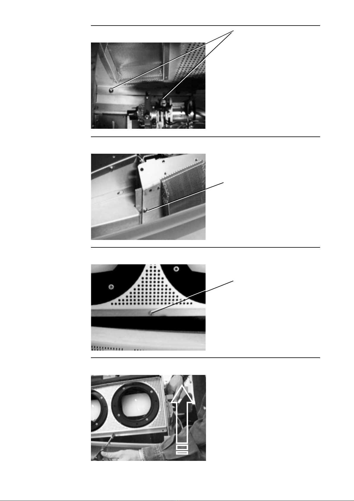
Image 8 The correct panels (1,2,3) by r-g-b ...................................................................................................... 9
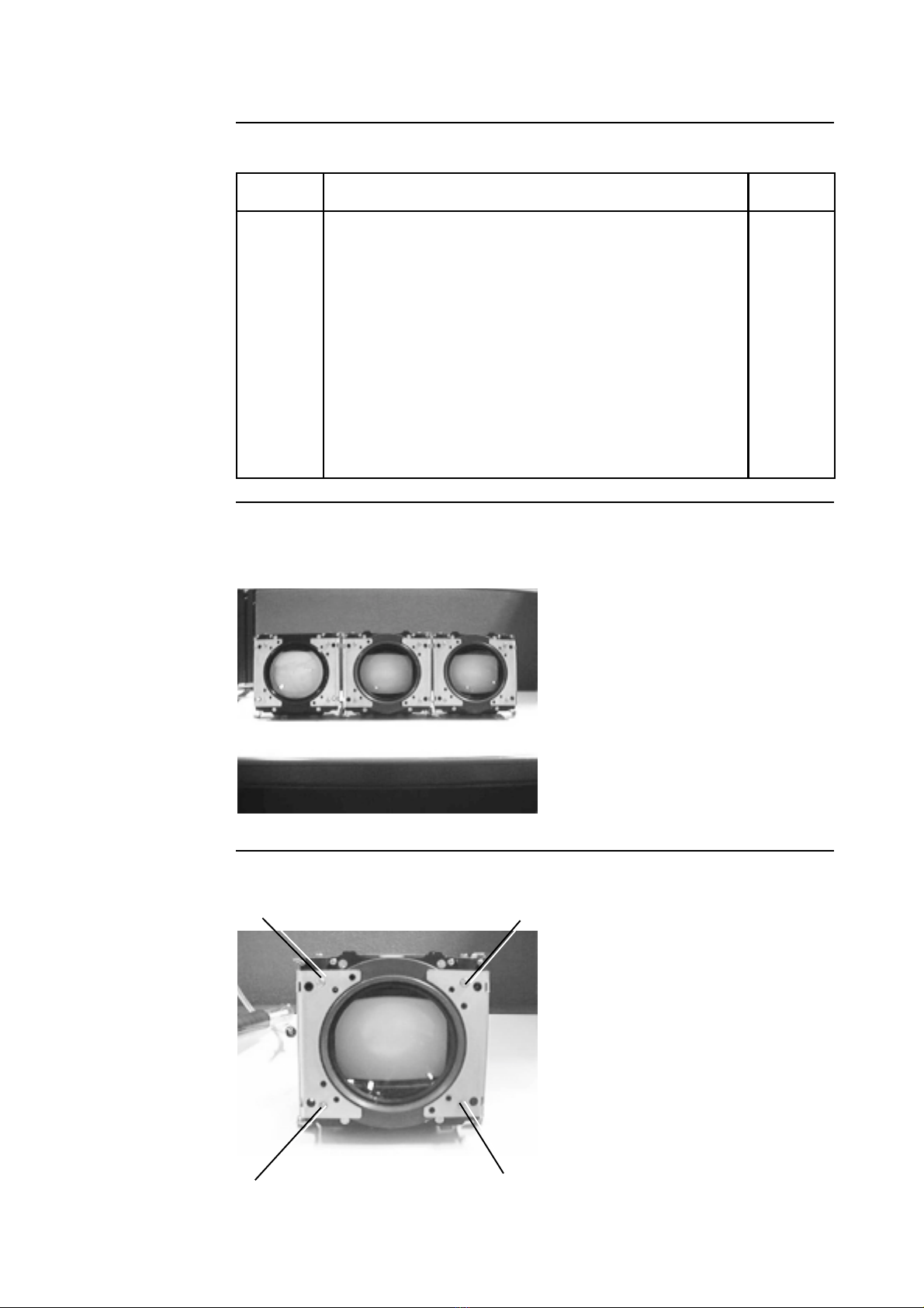
Image 9 Pos t on correct on w th screws ........................................................................................................... 9
Procedure 5 ....................................................................................................................................................10
Illustrat on together ..........................................................................................................................................10
Image 12 .........................................................................................................................................................10
REPLACEMENT OF THE THREE PICTURE TUBE TOGETHER ............................... 11
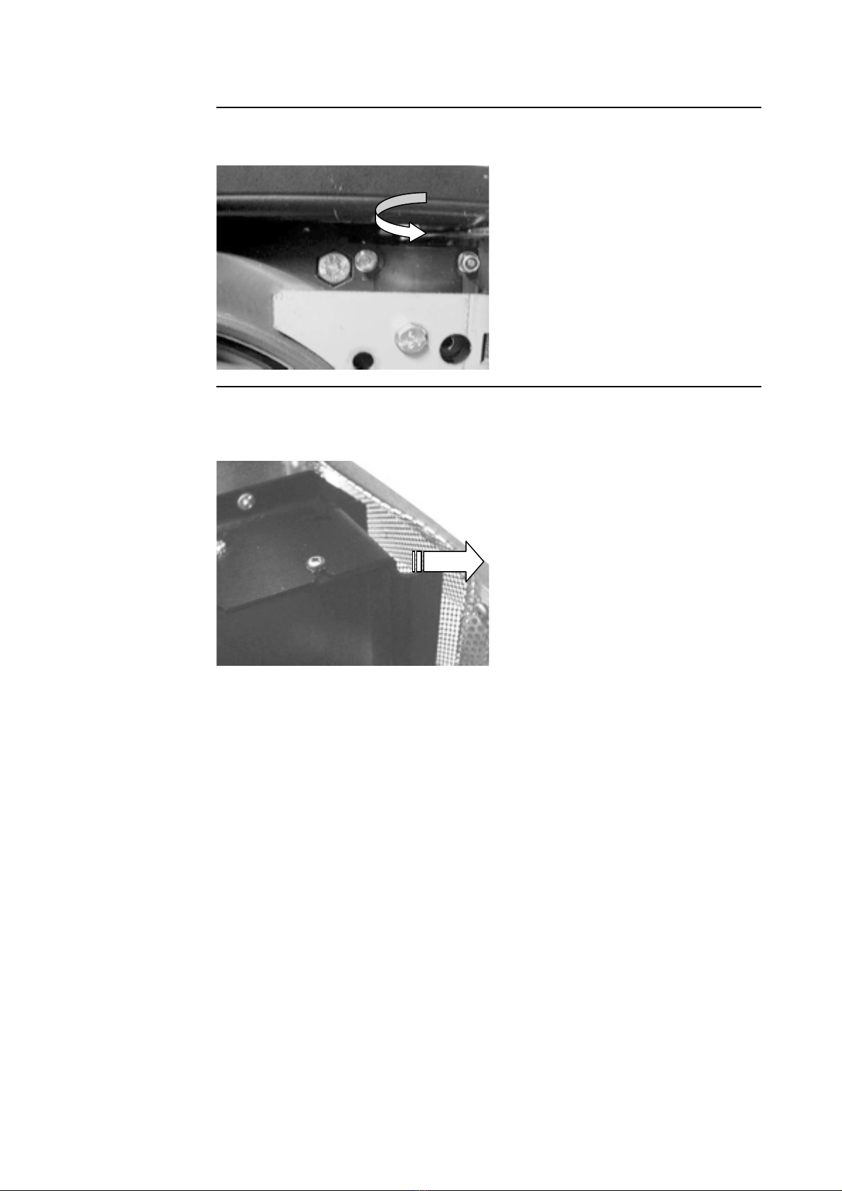
Image 10 Adjustment ...................................................................................................................................... 11
Image 11 End stage touches frame ................................................................................................................. 11
REPLACEMENT OF A PICTURE TUBE IN THE B*120* ERIE PROJECTOR ........ 12
What has to be done .......................................................................................................................................12
Procedure 1 ....................................................................................................................................................12
Image 13 .........................................................................................................................................................12
Procedure 2 ....................................................................................................................................................13
Image 14 .........................................................................................................................................................13
Procedure 3 ....................................................................................................................................................13
Images 15 .......................................................................................................................................................14
CHEIMPFLUG ADJU TMENT (DIAGONAL IMAGE FOCU ING) ................................ 15
What has to be done .......................................................................................................................................15
Adjustment procedure: ....................................................................................................................................15
Image 16 .........................................................................................................................................................15
Image 17 .........................................................................................................................................................16
Image 18 .........................................................................................................................................................16
Image 19 .........................................................................................................................................................17
Image 20 .........................................................................................................................................................17

BARCO 5 Projection Systems
Procedure For The Replacement Of The 9inch Picture
Tubes
What has to be
done
Replacement of the 9 adjustable picture tubes
Applicable On the follo ing kits:
R76281622K
R76281655K
R76281666K
Procedure 1 Follo the next procedure:
1
2
3
4
5
6
Remove the top cover
Disconnect the end stage, deflection, focus, ..
Remove the lens
Remove the 4 scre s fixing the picture tube
Click out the Picture tube and remove all the electronics
(place it on the ne CRT).
Click in the ne Picture tube and fix it ith the same
scre s (smallest scre s).
Step Action Image

BARCO 6 Projection Systems
Replacement of 9 fixed pictures tubes with adjustable
tubes.
What has to be
done
Replacement of the 9 fixed picture tubes ith the adjustable picture tubes
applicable on the follo ing kits:
R7624302K /5K /6K
R7626412K /5K /6K
R7624312K /5K /6K
R762142K /5K /6K
Image 1
Procedure 2 Follo the next procedure:
1
2
3
4
5
4
123
5
123
Place the device ith its bottom on the floor: the picture
tubes can not be replaced hile the projector is mounted
on the ceiling
Remove the top cover
Remove the protection cover panel (top side)/opening
Remove the Lenses
Remove the perforated protection panel (front side/14
scre s)
Attention: for the 2 scre s on the under side you have to
loosen the complete picture tube frame (2x5 scre s) and
lift it up
Scre s to loosen the picture tube frame
Picture tube frame fixing: the protection panel is not
remounted for the ne picture tubes but replaced by
protection corner pieces (see 10)
Attention: Therefore 6 scre s of the old protection panel
must be reused
Step Action Image

BARCO 7 Projection Systems
Image 2
Image 3
Image 5 lifting
out the picture
tube
Image 4 difficult
to reach screws

BARCO 8 Projection Systems
Removing of the picture tubes
Image 6
mounting screws
(6x
Image 7 remove
PCB board
1
2
3
4
7
6
Loosen the end stage, deflection, focus,
Remove PCB board at the end of the picture tube (4
scre s)
Loosen the mounting scre s on the top panel and lo er
panel ( ill be reused)
Slide out the picture tubes
Step Action Image
Procedure 3 To remove the picture tubes, follo the next procedure:

BARCO 9 Projection Systems
uilding in the new picture tubes
Image 8 The
correct panels
(1,2,3 by r-g-b
Image 9 Position
correction with
screws
Procedure 4 - Replacing 1 picture tube: follo the next procedure:
1
2
3
8,9
9
Fix the mounting panels on the picture tube
slide in the ne picture tube and reconnect the end stage
fix the picture tube block on the lo er panel and top panel
NOTE: If necessary you can correct the position of the
mounting panel ith respect to the picture tube block by
loosening the scre s in the front (4 scre s are supplied)
see also the numbers on the panels
NOTE: difference bet een picture tubes:
by colored label : red ,green & blue
by last digit of the art. No. red=2, green=5, blue=6
Step Action Image
BGR
3 1 2 1 2 3

BARCO 10 Projection Systems
Image 12
uilding in the new picture tubes (Continued)
Procedure 5 Replacement of the three picture tubes together:
Bl
E
F
Gr
C
D
Rd
A
B
Illustration
together
1
2
3
4
5
6
7
8
9
6
9
12
12
10,11
First mount the mounting scre s
mount panel A (scre top)
Slide in the red picture tube and reconnect the end stage
Mount panel B and C (scre top and bottom)
Slide in the green and blue picture tubes and reconnecting
their end stage
Mount panel D and E (scre top and bottom)
Mount panel F (scre top)
Fix the panels on the picture tubes (4 scre s are supplied
ith each tube)
Ne (delivered) protection corner pieces (2x) to mount on
the side panels of the picture tube frame (2x3 scre s
(reused from the old protection panel))
Mounting the protection pieces (2x3 scre s)
Reinstall the protection panel and the top cover
Additional information on the follo ing kits:
R7621042K/ 5K/ 6K
Scheimpflug Adjustment
Step Action Image

BARCO 11 Projection Systems
Replacement of the three picture tubes together
Image 10
Adjustment
Image 11 End
stage touches
frame

BARCO 12 Projection Systems
Replacement of a Picture Tube in the *120* series
projectors
What has to be
done
Red Picture Tube: Kit NR R7621042K
Green Picture Tube: Kit NR R7621045K
Blue Picture Tube: Kit NR R7621046K
ATTENTION: each Kit consists of a picture tube R762430-2 (R), -5 (G) or -6 (B)
together ith the Video amplifier R762292
(Notice that the picture tube R762104-2, -5 and -6 is replaced in the same kit by an
other type of picture tube together the Video-amplifier)
RG B
Image 13
Procedure 1 Replacement of a picture tube ith the above mentioned kit requires the adaptation of
the follo ing modules:
1
2
3
13Deflection S itching module
Convergence module
Replacement of the Video amplifier
Step Action Image

BARCO 13 Projection Systems
WIDTH Coils
Red
Picture Tube
WIDTH Coils
Green
Picture Tube
WIDTH Coils
Blue
Picture Tube
Image 14
Replacement of a Picture Tube in the *120* series
projectors (Continued)
Procedure 3 Adaptation Convergence module ONLY in the follo ing configuration, follo the next
procedure: FrontTable and RearCeiling
Procedure 2 Adaptation of the Deflection S itching module, follo the next procedure:
114
The width of the projected picture of the picture tube
R762104-2, -5 and -6 is larger than its replacement picture
tube R762431-2, -5 and -6.
To enlarge the width of the projected picture for the
replacement part, short-circuit the corresponding WIDTH
coils on the Deflection Switching module.
ATTENTION: before proceeding to the short-circuit of the
respective WIDTH Coil, activate CONVERGENCE OFF in
the SERVICE-Menu to switch the Convergence adjust-
ments in their mid-position.
WIDTH Adjustment: adjust the WIDTH-Coils of the not
replaced picture tubes for equal picture Width.
Step Action Image
1
2
15
The adaptation of the module consists of a readjustment of
Pulse 2 (P802).
Connect an oscilloscope to resistor R885 (or emitter of
transistor Q804)
Adjust the potentiometer P802 for a pulse duration of the
Pulse 2 of 2.5us on emitter of transistor Q804.
Step Action Image

BARCO 14 Projection Systems
Replacement of a Picture Tube in the *120* series
projectors (Continued)
Images 15 Pulse duration PULSE 2 P802 '2.5us'
0.5us
2.0us
WDEOHPRXQWHGSURMHFWRU
FHLOLQJPRXQWHGSURMHFWRU
0.5us
3 5
3
3
3
5
5 5
7
6 2172c

BARCO 15 Projection Systems
5('*5((1%/8(
$ $ $ $ $ $
% % % % % %
:$51,1*72$'-8676&+(,03)/8*&255(&7,216$72$
),567/226(17+(&255(6321',1*6(&85,7<1876%72%
6&+(,03)/8*$'-8670(17,6/,0,7('
352-(&725)52179,(:
:$51,1*:$51,1*:$51,1*
:$51,1*:$51,1*:$51,1*
:$51,1*:$51,1*
:$51,1*:$51,1*
Scheimpflug Adjustment (Diagonal image focusing)
What has to be
done
With the diagonal image focusing corrections, it is possible to obtain uniform focus for
the total projected image.
These corrections must be repeated for each color. The Diagonal image focusing is
repeated 3 times, first for green, then for red and then for blue.
Image 16
1
2
3
4
5
16
17
18
19
20
First, be sure that the CRT projection angle is correctly
adjusted, other ise it is not possible to obtain proper
overall focus of the image.
Press ENTER to start the green adjustment.
Press EXIT to return to CRT Projection Angle Adjustment.
Loosen first the security scre s (see images opposite and
above.)
Example : diagonal focusing of the green image.
Equalize diagonally the focus from left (bottom) to right
(top) by turning scre A3 of the projected color.
Equalize no diagonally the focus from left (top) to right
(bottom) by turning scre A4 located under the green lens.
Repeat the same procedure for the red and blue image
using the corresponding scre s.
To optimize the image focusing, repeat the optical lens
focusing.
When the scheimpflug corrections are correctly adjusted,
secure this position by fastening the security scre s on
both sides of each lens.
Warning : When the security screws are tightened, it is not
possible to change the scheimpflug correction.
After finishing the Installation Adjustment Procedures, the
main menu returns on the screen. You are no able to start
the alignment procedure for the projector.
For detailed information about these adjustments, please
refer to the O ner's Manual of the projector.
Step Action Image
Adjustment
procedure:
Follo the next procedure:

BARCO 16 Projection Systems
Scheimpflug Adjustment (Diagonal image focusing)
(Continued)
A3
A4 A1
A2
A5
A6
GREEN A3 A4
RED A5 A6
BLUE A1 A2
left
right
left
right
Image 18
Image 17
DIAGONAL IMAGE FOCUSING
<ENTER> to continue
<EXIT> to return
1. TURN THE SCREW MARKED
;;
TO FOCUS THE IMAGE DIAGO-
NALLY from LEFT (bottom) TO
RIGHT (top).
2. TURN THE SCREW MARKED
;;
TO FOCUS THE IMAGE DIAGO-
NALLY from LEFT (top) TO RIGHT
(bottom)
B5 B6
Red CRT Lens
B4

BARCO 17 Projection Systems
enter
password
xxxx
197
ADJUSTMENT MODE
Select a path from
below:
GUIDED
RANDOM ACCESS
INSTALLATION
SERVICE
IRIS
Select with or
then <ENTER>
<EXIT> to return
+
+
+
+
+
+
+
LENS
CENTER FOCUSING
GREEN IMAGE
RED IMAGE BLUE IMAGE
DIAGONAL IMAGE FOCUSING
from left top to right bottom
EROW$
EROW$
EROW$
EROW$
EROW$
e.g. : Turning bolt A5 will influence the diagonal focus for Red from left bottom to right top
EROW$
CORNER FOCUSING
DIAGONAL IMAGE FOCUSING
fromleft bottomto right top
+
Scheimpflug Adjustment (Diagonal image focusing)
(Continued)
Image 20
Image 19
This manual suits for next models
26
Table of contents
Other Barco Projector manuals

Barco
Barco SIM 5R User manual

Barco
Barco G50 User manual

Barco
Barco R9001180 User manual

Barco
Barco FLM HD14 User manual

Barco
Barco SIM 7Q User manual

Barco
Barco R9898170 User manual

Barco
Barco R9000904 User manual

Barco
Barco MGP D5 Instruction Manual

Barco
Barco R9001330 User manual

Barco
Barco BARCOREALITY SIM 6 MK II + WARP 6 User manual

Barco
Barco R9001490 User manual

Barco
Barco VISION 3200LC User manual

Barco
Barco UDM Series User manual

Barco
Barco R9002250 User manual

Barco
Barco F50 User manual

Barco
Barco CV series User manual

Barco
Barco CLM HD8 Manual

Barco
Barco R9001890 User manual

Barco
Barco Cineo12 User manual

Barco
Barco BarcoReality SIM6 Ultra R9040150 User manual