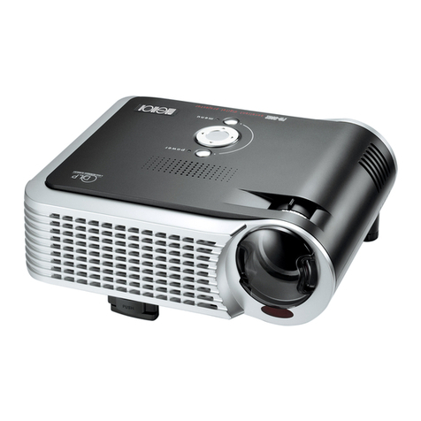
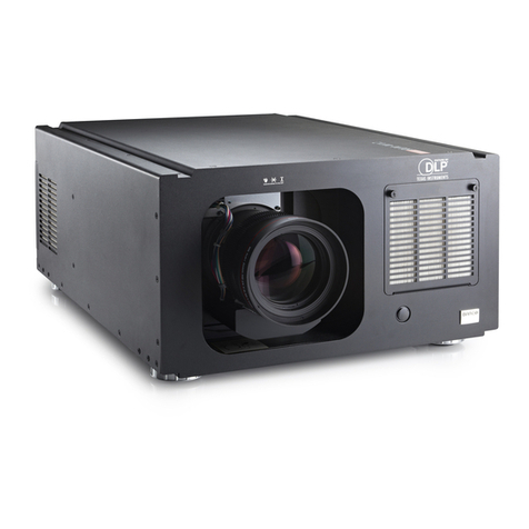
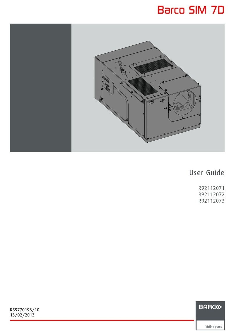
Barco SLM R12 Plus User manual

SLM R12+ Performer
Service Manual
R9010170
R9010171
R5976820/00
08/03/2005

Barco nv Events
Noordlaan 5, B-8520 Kuurne
Phone: +32 56.36.89.70
Fax: +32 56.36.88.24
E-mail: [email protected]
Visit us at the web: www.barco.com
PrintedinBelgium

Table of contents
TABLE OF CONTENTS
1. Safety.................................................................................................................. 7
1.1 SafetyInstructions .................................................................................................................... 7
2. General Info SLM R12+ P .........................................................................................11
2.1 Performances ........................................................................................................................11
2.2 Specifications.........................................................................................................................12
3. SLM R12+ P - Parts.................................................................................................13
3.1 SLM R12+ P - List of Modules.......................................................................................................13
3.2 SLMR12+P-ListofKits............................................................................................................15
3.3 SLM R12+ P - List of Lenses ........................................................................................................15
4. SLM R12+ P - Location of the modules.........................................................................17
4.1 Projectorside-Left ..................................................................................................................17
4.2 Projectorside-Right.................................................................................................................18
4.3 Projector-ElectronicBox............................................................................................................19
4.4 Projector-Accessories ..............................................................................................................27
5. SLM R12+ P - Location of the Fans .............................................................................29
5.1 Fans - Mounted on Air Outlet ........................................................................................................29
5.2 Fans - Mounted on Projector Frame.................................................................................................29
5.3 Fans - Mounted on the Electronic Box ..............................................................................................31
5.4 Fans - Mounted on Optical Base ....................................................................................................31
5.5 Fans - Mounted on Light Engine.....................................................................................................32
5.6 Fans - Mounted on the Lamp Power Supply ........................................................................................33
6. Interconnection diagram..........................................................................................35
6.1 Interconnection diagram .............................................................................................................35
7. IR Transmitter RC-5 Coded R763569............................................................................37
7.1 General Info ..........................................................................................................................37
7.2 AccesstotheIRTransmitterBoard .................................................................................................38
7.3 BatteryPlugin........................................................................................................................38
7.4 TechnicalInfo.........................................................................................................................40
7.5 TechnicalDescription ................................................................................................................41
8. Local Keypad & LCD Display.....................................................................................43
8.1 General Info ..........................................................................................................................43
8.2 Module replacement .................................................................................................................43
8.3 TechnicalDescription ................................................................................................................44
8.4 StatusConditions&FaultAnalysis..................................................................................................46
8.4.1 ErrorListonLCDandINFOdisplay..........................................................................................46
8.4.2 ErrorListonINFOdisplayOnly...............................................................................................52
9. Communication Module R763768 ...............................................................................55
9.1 General Info ..........................................................................................................................55
9.2 Interconnection with CPU............................................................................................................56
9.3 Technicaldescription.................................................................................................................57
9.4 On board connector pin assignment.................................................................................................59
9.5 On board Information Display........................................................................................................64
9.5.1 View of the board..............................................................................................................64
9.5.2 TechnicalInfo..................................................................................................................64
9.5.3 ErrorListonINFOdisplayOnly...............................................................................................65
10.Serial Digital Input Module R7632485...........................................................................67
10.1 General Info ..........................................................................................................................67
10.2 TechnicalInfo.........................................................................................................................67
11.Signal Input Selection R763850 & R763851....................................................................69
11.1 General Info ..........................................................................................................................69
11.2 Block Diagram Signal Input Selection 1 & 2.........................................................................................70
11.3 Technical Description Input Selector 1 & 2..........................................................................................71
11.3.1 Technical Description Input Selector 1........................................................................................71
11.3.1.1 General Description.....................................................................................................71
11.3.1.2 Detaileddescription(seeschematicssheet1/11to11/11.............................................................71
11.3.1.2.1 Analog Input and sync processing................................................................................71
11.3.1.2.2 DVI input (sheet 3/11).............................................................................................72
11.3.1.2.3 Analog to digital converter I4 (AD9888KS).......................................................................72
11.3.1.2.4 DVI Output (see sheet 3/11). .....................................................................................73
11.3.1.2.5 Data multiplexing (see sheet 7- 8/11) ............................................................................73
11.3.1.2.6 Syncswitchingandcontrol,I25(sheet9/11).....................................................................73
11.3.1.2.7 Powersection.....................................................................................................74
11.3.2 Technical Description Input Selector 2........................................................................................74
11.3.2.1 General Description.....................................................................................................74
R5976820 SLM R12+ PERFORMER 08/03/2005 1

Table of contents
11.3.2.2 Analog input and sync processing......................................................................................74
11.3.2.3 DVI Input ................................................................................................................74
11.4 Power Supply ........................................................................................................................75
11.4.1 PowerDiagramforInputSelectionmodule1.................................................................................75
11.4.2 PowerDiagramforInputSelectionmodule2.................................................................................78
12.Digital Decoder R763826..........................................................................................81
12.1 General Info ..........................................................................................................................81
12.2 BlockDiagramDigitalDecoder......................................................................................................82
12.3 TechnicalDescription ................................................................................................................83
12.3.1 General ........................................................................................................................83
12.3.2 Functional Description.........................................................................................................83
12.3.3 Power Supply..................................................................................................................84
13.Digital Inputs Backplane R763378...............................................................................85
13.1 General Info ..........................................................................................................................85
13.2 Power Supply Monitoring ............................................................................................................85
13.3 Interconnection with Communication Interface......................................................................................87
14.Power Distribution Backplane R764239........................................................................89
14.1 General Info ..........................................................................................................................89
14.2 Pin Assignment Connectors on Board...............................................................................................90
14.2.1 Euro-Connectors...............................................................................................................90
14.2.2 Wire-Connections..............................................................................................................91
14.2.2.1 Wire-connections to FANs ..............................................................................................91
14.2.2.2 Wire-connections to Modules...........................................................................................96
15.Lamp Power Supply R7633705................................................................................. 101
15.1 General Info .........................................................................................................................101
15.2 TechnicalInfo........................................................................................................................102
15.3 Interconnection Diagrams...........................................................................................................105
15.4 ControlsonBoard...................................................................................................................107
15.5 Technical Description LPS-X In/Out R7632113 ....................................................................................111
15.5.1 General .......................................................................................................................111
15.5.2 Functions on the module: ....................................................................................................111
15.5.3 EMCFilter-Rush-inCurrentLimit-MainsRectifier.........................................................................112
15.5.4 On-board SMPS. .............................................................................................................112
15.5.5 Secondary circuit of the LPS. ................................................................................................113
15.5.6 Measurement of the lamp voltage............................................................................................113
15.5.7 LampCurrentMeasurement..................................................................................................113
15.5.8 Boostupcircuit................................................................................................................114
15.5.9 Fandrive......................................................................................................................114
15.5.10LAMP_ONgreenLEDindication.............................................................................................114
15.6 TechnicalDescriptionLPS-XProcessingR7632105...............................................................................114
15.6.1 General .......................................................................................................................114
15.6.2 Controllercircuitsandcontrollerinterfacecircuits:..........................................................................114
15.6.3 PowerFactorCorrector(sheet4/5)..........................................................................................116
15.6.4 PrimaryLPS ..................................................................................................................118
15.7 Pin Assignment Connectors on Board..............................................................................................120
15.8 AdjustmentsonBoard ..............................................................................................................123
16.Start Pulse Generator (SPG) R763512........................................................................ 125
16.1 General Info .........................................................................................................................125
16.2 TechnicalInfo........................................................................................................................126
17.Switch Mode Power Supply (SMPS) R764349............................................................... 129
17.1 Introduction..........................................................................................................................129
17.2 TechnicalDescription ...............................................................................................................130
17.3 BlockDiagrams......................................................................................................................132
17.4 Pin Assignment Connectors on Board..............................................................................................135
17.5 StatusConditions/FaultAnalysis...................................................................................................137
18.Temperature & Motor Control Module R764203............................................................. 139
18.1 Introduction..........................................................................................................................139
18.2 TechnicalDescription ...............................................................................................................139
18.3 Pin Assignment Connectors on Board..............................................................................................144
19.Formatter Interface Board (FIB) R764346.................................................................... 147
19.1 Introduction..........................................................................................................................147
19.2 Power Supply........................................................................................................................148
19.3 Light Engine Connection............................................................................................................150
20.CPU Module R7638858 .......................................................................................... 153
20.1 Introduction..........................................................................................................................153
20.2 BlockDiagramCPU.................................................................................................................154
20.3 Power Supply on Board.............................................................................................................155
20.4 FunctionsonBoard .................................................................................................................155
2R5976820 SLM R12+ PERFORMER 08/03/2005

Table of contents
20.5 Interconnection Diagram............................................................................................................156
21.Pixel Map Processor Module R764115........................................................................ 157
21.1 ViewofthePMPModule............................................................................................................157
21.2 BlockDiagramPMP.................................................................................................................158
21.3 ShortTechnicalDescription.........................................................................................................159
21.4 Power Supply........................................................................................................................159
21.5 StatusConditions/FaultAnalysis..................................................................................................161
22.Infra Red Receiver Module R763261 .......................................................................... 163
22.1 ViewoftheInfraRedReceiver .....................................................................................................163
22.2 BlockDiagramIRReceiver.........................................................................................................163
22.3 Interconnection Diagram............................................................................................................164
23.Ambient Temperature Sensor R762790 ...................................................................... 167
23.1 ViewoftheAmbientTemperatureSensor..........................................................................................167
23.2 Interconnection Diagram............................................................................................................168
24.Projector Tilt Switch R764240.................................................................................. 169
24.1 ViewoftheprojectorTiltSwitch ....................................................................................................169
24.2 ProjectorTiltingProtection..........................................................................................................169
24.3 Interconnection Diagram............................................................................................................171
25.Light Output Sensor R763294.................................................................................. 173
25.1 ViewoftheLightOutputSensor....................................................................................................173
25.2 TechnicalInfo........................................................................................................................173
25.3 Interconnection with CPU...........................................................................................................175
26.Lamp Info Module R763295..................................................................................... 177
26.1 ViewoftheLampInfo...............................................................................................................177
26.2 Interconnection Diagram............................................................................................................178
26.3 TechnicalInfo........................................................................................................................179
27.Maintenance....................................................................................................... 181
27.1 Lens Block ..........................................................................................................................181
27.1.1 OverviewofMicroSwitchesandMotors.....................................................................................181
27.1.2 Disassembling the Lens Block ...............................................................................................181
27.1.3 DisassemblingaMotorUnit..................................................................................................183
27.2 Cleaning/Replacement of the Dust Filters..........................................................................................186
27.2.1 LocationoftheDustFilters...................................................................................................187
27.2.2 Cleaning/Replacement of the Dust Filters ...................................................................................187
27.2.2.1 Dustfilteronthefrontsideoftheprojector ...........................................................................187
27.2.2.2 Dustfiltersontherearsideoftheprojector...........................................................................188
27.3 LampReplacement .................................................................................................................191
27.3.1 SafetyWarnings..............................................................................................................191
27.3.1.1 Safetywarningsduringinstallation....................................................................................191
27.3.1.2 Product care............................................................................................................191
27.3.2 Introduction ...................................................................................................................192
27.3.2.1 Contentofthekit.......................................................................................................192
27.3.3 Removingtheoldlamp.......................................................................................................192
27.3.3.1 AccesstotheLampUnit...............................................................................................192
27.3.3.2 RemovingtheLampUnit...............................................................................................193
27.3.4 InsertingthenewlampUnit..................................................................................................194
27.3.4.1 InstallationofthenewLampUnit......................................................................................194
27.3.4.2 OpticalAlignmentofthelamp.........................................................................................196
27.3.4.3 Reinstalling the Side Panel ............................................................................................197
27.4 Re-convergence.....................................................................................................................198
27.4.1 Re-ConvergenceKit..........................................................................................................198
27.4.1.1 Purposeofthekit ......................................................................................................198
27.4.1.2 ContentsoftheKit.....................................................................................................198
27.4.1.3 RelevantTestPattern..................................................................................................199
27.4.2 Preparation Projector for Re-Convergence..................................................................................199
27.4.2.1 AccesstoLightEngine ................................................................................................200
27.4.2.1.1 Removing the Input Assembly...................................................................................200
27.4.2.1.2 RemovingtheBackCover.......................................................................................200
27.4.2.1.3 Removingthetopcover.........................................................................................201
27.4.2.2 Disconnection Fans on Light Engine..................................................................................202
27.4.2.2.1 RemovingthePrismCoolingFan...............................................................................202
27.4.2.2.2 RemovingtheEngineCoolingFan..............................................................................203
27.4.2.2.3 ElectricaldisconnectionoftheFans ............................................................................203
27.4.2.3 Temporarily Replacement of the Air Channel.........................................................................204
27.4.2.3.1 Removal of the Air Channel .....................................................................................205
27.4.2.3.2 Installation of the Service Air Channel (Part of the kit) .........................................................206
27.4.3 Re-convergence the Light Engine ...........................................................................................207
27.4.3.1 Action of the convergence controls....................................................................................207
27.4.3.2 Re-convergenceGREENonRED.....................................................................................209
27.4.3.2.1 Locationofcontrols..............................................................................................209
R5976820 SLM R12+ PERFORMER 08/03/2005 3

Table of contents
27.4.3.2.2 Re-convergingGreenDMD .....................................................................................210
27.4.3.2.3 Readjustment of the plungers ...................................................................................211
27.4.3.3 Re-convergenceBLUEonRED.......................................................................................213
27.4.3.3.1 Locationofcontrols..............................................................................................213
27.4.3.3.2 Re-convergingBlueDMD .......................................................................................214
27.4.3.3.3 Readjustment of the plungers ...................................................................................216
27.5 EngineReplacement................................................................................................................217
27.5.1 SafetyInstructions............................................................................................................217
27.5.1.1 General.................................................................................................................217
27.5.2 AccesstoImageProcessorUnit.............................................................................................218
27.5.2.1 RemovaloftheInputAssembly.......................................................................................218
27.5.2.2 Removing the side panel ..............................................................................................218
27.5.2.3 RemovaloftheBackCover ...........................................................................................219
27.5.2.4 Removing the Lens ....................................................................................................219
27.5.2.5 RemovaloftheTopCover.............................................................................................220
27.5.2.6 Removalofthelampunit..............................................................................................220
27.5.2.7 Removing the SM Power Supply Module .............................................................................220
27.5.2.8 Removal of the Air Channel ...........................................................................................222
27.5.3 RemovingtheEngine.........................................................................................................222
27.5.3.1 Overview connections behind input box...............................................................................222
27.5.3.2 Disconnecting the formatter and DMD connections ..................................................................223
27.5.3.3 Removing the disconnected cables ...................................................................................225
27.5.3.4 Disconnect the lens sensor cable .....................................................................................226
27.5.3.5 Disconnect the shutter .................................................................................................226
27.5.3.6 Disconnect the lens holder ground leads .............................................................................227
27.5.3.7 Disconnecting the engine fans ........................................................................................227
27.5.3.8 Removing the engine ..................................................................................................228
27.5.4 Installing a new engine .......................................................................................................230
27.5.4.1 Mountingtheengine...................................................................................................230
27.5.4.2 Guidingthecables.....................................................................................................232
27.5.4.3 Connecting the engine fans ...........................................................................................233
27.5.4.4 Mounting the lens holder ground leads ...............................................................................236
27.5.4.5 Connecting the shutter.................................................................................................237
27.5.4.6 Connecting the lens sensor............................................................................................237
27.5.5 Re-assemblingtheprojector.................................................................................................238
27.5.5.1 Mounting the Air channel ..............................................................................................238
27.5.5.2 Removing the SM Power Supply Module .............................................................................239
27.5.5.3 InstallationoftheLampUnit...........................................................................................241
27.5.5.4 Mountingthetopcover ................................................................................................242
27.5.5.5 Reinstalling the Side Panel ............................................................................................243
27.5.5.6 LensInstallation........................................................................................................244
27.5.5.7 Mountingthebackcover...............................................................................................245
27.5.5.8 Inserting the Input panel...............................................................................................245
27.6 ReplacementoftheLightIntegrationRod..........................................................................................246
27.6.1 GeneralInfo...................................................................................................................246
27.6.2 Replacement procedure......................................................................................................247
27.6.2.1 Removing the air channel unit.........................................................................................247
27.6.2.2 Removing the start pulse generator...................................................................................249
27.6.2.3 RemovaloftheLightIntegrationRod.................................................................................250
27.6.2.4 InstallationoftheLightIntegrationRod...............................................................................251
27.6.3 AlignmentoftheLightIntegrationRod.......................................................................................252
27.6.3.1 Selectinternalblackpuritypattern ....................................................................................253
27.6.3.2 Accesstothecontrolsforthealignment..............................................................................254
27.6.3.3 FocusingtheLightSpot................................................................................................254
27.6.3.4 Matching the Light Spot to the DMDTM outline........................................................................255
28.Upgrade with Air Filters......................................................................................... 257
28.1 AirFilterUpgradeKitforSLMR12+................................................................................................257
28.1.1 LocationoftheDustFilters...................................................................................................257
28.1.2 ContentsoftheKit............................................................................................................257
28.2 DisassemblingtheprojectorforCoverreplacement...............................................................................258
28.2.1 Stepbystepactions..........................................................................................................258
28.2.2 DisassemblingSteps.........................................................................................................258
28.2.2.1 Removingthelampcover..............................................................................................258
28.2.2.2 Removing the Input Assembly.........................................................................................259
28.2.2.3 RemovingtheRearCover.............................................................................................259
28.2.2.4 RemovingtheTopCover ..............................................................................................260
28.2.2.5 RemovaloftheCarryingHandle ......................................................................................262
28.2.2.6 RemovaloftheBottomCover.........................................................................................263
28.3 Reassemblingtheprojectorwithkitparts..........................................................................................264
28.3.1 Stepbystepactions..........................................................................................................264
28.3.2 ReassemblingSteps..........................................................................................................264
28.3.2.1 AdaptationoftheSafetycabletighteningunit ........................................................................264
28.3.2.2 MountingtheBottomCoverwithAirFilters...........................................................................266
28.3.2.3 Mounting the Carrying handle fixation studs..........................................................................266
28.3.2.4 MountingtheCarryingHandle.........................................................................................267
4R5976820 SLM R12+ PERFORMER 08/03/2005

Table of contents
28.3.2.5 MountingtheremovedStackinginterlocks............................................................................267
28.3.2.6 MountingtheIRReceiverUnit.........................................................................................268
28.3.2.7 MountingtheBottomCoverwithAirFilters...........................................................................270
29.Overview of the Electrical Diagrams.......................................................................... 271
29.1 ElectricalDiagrams..................................................................................................................271
A. Specifications ..................................................................................................... 273
A.1 SLMR12+PSpecifications.........................................................................................................273
Index.................................................................................................................... 275
R5976820 SLM R12+ PERFORMER 08/03/2005 5

Table of contents
6R5976820 SLM R12+ PERFORMER 08/03/2005
1. Safety
1. SAFETY
1.1 Safety Instructions
WARNING:Before Removing/Replacing any projector components, turn off the Main Power Switch and un-
plug the Main AC power cable.
R5976820 SLM R12+ PERFORMER 08/03/2005 7
1. Safety
Safety Instructions
1. Before returning an instrument to the customer, always make a safety check of the entire instrument, including, but not limited
to, the following items:
a) Be sure that no built-in protective devices are defective and/or have been defeated during servicing. (1) Protective shields
are provided on this chassis to protect both the technician and the customer. Correctly replace all missing protective shields,
including any removed for servicing convenience. (2) When reinstalling the chassis and/or other assembly in the cabinet,
be sure to put back in place all protective devices, including, but not limited to, insulating materials, barriers, covers/shields,
and isolation resistor/capacitor networks. Do not operate this instrument or permit it to be operated without all protective
devices correctly installed and functioning. Servicers who defeat safety features or fail to perform safety checks may be
liable for any resulting damage.
b) Be sure that there are no cabinet openings through which an adult or child might be able to insert their fingers and contact a
hazardous voltage. Such openings include, but are not limited to, (1) excessively wide cabinet ventilation slots, and (2) an
improperly fitted and/or incorrectly secured cover panels.
c) Leakage Current Hot Check. With the instrument completely reassembled, plug the AC line cord directly into a 220 V AC
outlet (Do not use an isolation transformer during this test). Use a leakage current tester or a metering system that complies
with American National Standards Institute (ANSI) C101.0 Leakage Current for Appliances and Underwriters Laboratories
(UL) 1410, (50.7). With the instrument AC switch first in the on position and then in the off position, measure from a known
earth ground (metal waterpipe, conduit, etc.) to all exposed metal parts of the instrument (antennas, handle bracket, metal
cabinet, screwheads, metallic overlays, control shafts, etc.). especially any exposed metal parts that offer an electrical
return path to the chassis. Any current measured must not exceed 1.5 mA. Reverse the instrument power cord plug in the
outlet and repeat test. ANY MEASUREMENTS NOT WITHIN THE LIMITS SPECIFIED HEREIN INDICATE A POTENTIAL
SHOCK HAZARD THAT MUST BE ELIMINATED BEFORE RETURNING THE INSTRUMENT TO THE CUSTOMER OR
BEFORE CONNECTING ACCESSORIES.
Leakage Current Tester
Reading should
not be above
1.5 mA
Test all exposed metal surfaces
Earth
Ground
+-
Device Under Test
2-Wired cord
Also test with plug reversed
(Using AC Adapter plug as required)
AC Leakage Test
Image 1-1
AC Leakage Test
d) Ultraviolet Radiation exposure - Warning: This lamp can cause serious skin burn and eye inflammation from shortwave
ultraviolet radiation if not operated in enclosed fixtures. DO NOT operate this lamp in a fixture with a missing or broken lens
cover.
e) Ozone: Operating lamp generates ozone gas which is harmful to the respiratory system. Therefore the lamp should be
operated in adequately ventilated equipment.
2. Read and comply with all caution and safety-related notes on or inside the projector cabinet or on the projector chassis, or on
the picture tube.
3. Design Alteration Warning - Do not alter or add to the mechanical or electrical design of this apparatus. Design alterations and
additions, including, but not limited to, circuit modifications and the addition of items such as auxiliary audio and/or video output
connections, might alter the safety characteristics of this apparatus and create a hazard to the user. Any design alterations
or additions may void the manufacturer’s warranty and may make you, the servicer responsible for personal injury or property
damage resulting therefrom.
4. Lamp explosion Protection Warning – The lamp in this projector operates with a high internal pressure and there is a slight risk
that the lamp may explode, particularly if it is used beyond its rated life of 1000 hours. Do not remove, install, or otherwise
handle the lamp in any manner without first putting on shatterproof goggles equipped with side shields. People not so equipped
must be kept safely away while lamps are handled. Keep the lamp away from your body. For continued explosion protection,
replace the lamp only with one of the same type number. Always replace the lamp before the rated life time.
8R5976820 SLM R12+ PERFORMER 08/03/2005
1. Safety
5. Hot Chassis Warning - This projector chassis has two ground systems: the primary ground system is formed by the negative
voltage of the rectified mains (power) and is only used as a reference in primary circuits; the secondary ground system is
connected to earth ground via the earth conductor in the mains (power) lead. Separation between primary and secondary
circuits is performed by the safety isolation transformers. Components bridging this transformers are also safety components
and must never be defeated or altercated. All user-accessible conductive parts must be connected to earth ground, or are kept
at SELV (Safety Extra Low Voltage).
6. Observe original lead dress. Always inspect in all areas for pinched, out-of-face, or frayed wiring. Do not change spacing
between components, and between components and the printed-circuit board. Check AC power cord for damage. Take extra
care to assure correct lead dress in the following areas:
a) near sharp edges
b) near thermally hot parts - be sure that leads and components do not touch thermally hot parts
c) the AC supply
d) high voltage
7. Components, parts, and/or wiring that appear to have overheated or are otherwise damaged should be replaced with compo-
nents, parts, or wiring that meet original specifications. Additionally, determine the cause of overheating and/or damage and, if
necessary, take corrective action to remove any potential safety hazard.
8. PRODUCT SAFETY NOTICE - Many electrical and mechanical parts have special safety-related characteristics some of which
are often not evident from visual inspection, nor can the protection they give necessarily be obtained by replacing them with
components rated for higher voltage, wattage, etc. Use of a substitute replacement that does not have the same safety charac-
teristics as the recommended replacement part in BARCO service data parts list might create shock, fire, and/or other hazards.
Product Safety is under review continuously and new instructions are issued whenever appropriate. For the latest information,
always consult the appropriate current BARCO service literature.
9. Do not spray chemical on or near this instrument or any of its assemblies.
10. Electrostatically Sensitive (ES) Devices Some semiconductor (solid state) devices can be damaged easily by static electricity.
Such components commonly are called Electrostatically Sensitive (ES) Devices. Examples of typical ES devices are integrated
circuits and some field-effect transistors and semiconductor "chip" components. The following techniques should be used to
help reduce the incidence of component damage caused by static electricity:
a) Immediately before handling any semiconductor-equipped assembly, drain off any electrostatic charge on your body by
touching a known earth ground. Wear a commercially available high impedance discharging wrist strap device.
b) After removing an electrical assembly equipped with ES devices, place the assembly on a static dissipative surface such as
a 3M No 8210 table mat, to prevent electrostatic charge buildup or exposure of the assembly.
c) Do not use freon-propelled chemicals. These can generate electrical charges sufficient to damage ES devices.
d) Do not remove a replacement ES device from its protective package until immediately before you are ready to install it
(Most replacement ES devices are packaged with leads electrically shorted together by conductive foam, aluminium foil or
comparable conductive material).
e) Immediately before removingthe protective material from the leads of a replacement ES device, touch the protective material
to the chassis or circuitassembly into which the devicewill be installed. CAUTION: Be sure nopower is applied to thechassis
or circuit, and observe all other safety precautions.
f) Minimize bodily motions when handling unpacked replacement ES devices (Otherwise harmless motion such as the brush-
ing together of your clothes fabric or the lifting of your foot from a carpeted floor can generate static electricity sufficient to
damage an ES device).
R5976820 SLM R12+ PERFORMER 08/03/2005 9

1. Safety
10 R5976820 SLM R12+ PERFORMER 08/03/2005

2. General Info SLM R12+ P
2. GENERAL INFO SLM R12+ P
2.1 Performances
Overview
Image 2-1
Performances
R5976820 SLM R12+ PERFORMER 08/03/2005 11
2. General Info SLM R12+ P
2.2 Specifications
Overview
Image 2-2
Specifications
12 R5976820 SLM R12+ PERFORMER 08/03/2005

3. SLM R12+ P - Parts
3. SLM R12+ P - PARTS
Spare abbreviation
Abbreviation Definition
NR Non repairable
CO Consumable
FR Factory Repairable
LR Locally repairable
3.1 SLM R12+ P - List of Modules
Control Panel - Overview modules
Spare abbreviation
Art. Number Order Number Description
NR CO FR LR
R763223 Local keypad + LCD Display
R763279 LCD Display
R763768 Communication Unit
R763090 Communication Display
R763766 Communication Interface
Signal Input - Overview Modules
Spare abbreviation
Art. Number Order Number Description
NR CO FR LR
R7632485 R9840110 SDI Input (standard)
R763850 Input Selection 1/2 (standard)
R763851 Input Selection 2/2 (standard)
R763291 R9840450 HDTV-SDI Input (optional)
R763790 R9841170 (S)-Video Input +Decoder ( (optional)
Signal Processing - Overview Modules
Spare abbreviation
Art. Number Order Number Description
NR CO FR LR
R763261 Infra Red Receiver (Front & Rear)
R763826 Digital Decoder
R764115 Pixel Map Processor (PMP)
R7638858 CPU
R764346 Formatter Interface board (FIB)
R5976820 SLM R12+ PERFORMER 08/03/2005 13
3. SLM R12+ P - Parts
Light Engine - Overview Modules
Spare abbreviation
Art. Number Order Number Description
NR CO FR LR
R840527 R840527k Light Engine Complete
R764423 DLP 3CH SXGA+ Unit Blue
R764596 Formatter FTP* Blue
R764422 DLP 3CH SXGA+ Unit Green
R764595 Formatter FTP* Green
R7644221 DLP 3CH SXGA+ Unit Red
R7645951 Formatter FTP* Red
R764346 Formatter Interface board (FIB)
*Fast track Pixel
Power Supply - Overview Modules
Spare abbreviation
Art. Number Order Number Description
NR CO FR LR
R764349 Switch Mode Power Supply
R763512 Start Pulse Generator
R7632245S Start Pulse Generator Sub/2
R7633705 Lamp Power Supply-Xenon Mech/5
R7632113 Lamp Power Supply-Xenon In/Out/3
R7632105 Lamp Power Supply-Xenon Proc/5
Misceleneous
Spare abbreviation
Art. Number Order Number Description
R762790 Temperature Sensor
R763604 Remote Control Complete (RC5)
R763569 Remote Control board
R763294 Ambient Light Sensor
R763295 Lamp Info board
R764240 Tilt switch
R764239 Backplane Electronic box
R763378 Backplane Electronic box (Inputs)
14 R5976820 SLM R12+ PERFORMER 08/03/2005

3. SLM R12+ P - Parts
3.2 SLM R12+ P - List of Kits
Overview
Order Number Description Publication Reference
R840527K Light Engine Complete R5976786
R8454096K*
R84540924k*
Framed Air Filter (6 pack)
Framed Air Filter (24 pack)
xxxxxxx
R9841812 Lamp unit replacement R5976754
R9841170 Digital Video Input R5976226
R9840450 HDTV-SDI Input R5976226
R9841200 Network R5976325
R9841180 Toolkit R5976290
R9841080 Ceiling Mount 100 adapter plate R5976313
R9841010 Ceiling Mount 100 with Pulley R5976359
R9841011 Ceiling Mount 100 without Pulley R5976359
R9840840 Multi-funtional Frame R5976259
R9898215 Stackable Frame R5976400
R847196K Re-convergence Toolkit R5976814
R9840170 Rugged Remote Control R5976251
R9840172 Wireless Receiver R5976348
R9840171 Wireless Rugged Remote Control R5976251
*For the SLM R9+ only
3.3 SLM R12+ P - List of Lenses
Overview TLD High Brightness Lenses
Lens Reference Metric formulas (meter) Inch formulas (inch)
TLD HB(0.8:1) PD=0.77xSW+0.05 PD=0.77SW+1.97
TLD HB(1.2:1) PD=1.11xSW-0.01 PD=1.11xSW-0.39
TLD HB(1.6–2.0:1) PDmin=1.47xSW-0.09
PDmax=1.85xSW-0.13
PDmin=1.47xSW-3.54
PDmax=1.85xSW-5.12
TLD HB(2.0–2.8:1) PDmin=1.85xSW-0.17
PDmax=2.62xSW-0.24
PDmin=1.85xSW-6.69
PDmax=2.62xSW-9.45
TLD HB(2.8–5.0:1) PDmin=2.58xSW-0.16
PDmax=4.71xSW-0.38
PDmin=2.58xSW-6.30
PDmax=4.71xSW-14.96
TLD HB(5.0–8.0:1) PDmin=4.52xSW-0.01
PDmax=7.53xSW-0.29
PDmin=4.52xSW-0.39
PDmax=7.53xSW-11.42
R5976820 SLM R12+ PERFORMER 08/03/2005 15

3. SLM R12+ P - Parts
Overview TLD Lenses
Lens Reference Metric formulas (meter) Inch formulas (inch)
TLD(0.8:1) PD=0.77xSW+0.05 PD=0.77SW+1.97
TLD(1.2:1) PD=1.11xSW-0.01 PD=1.11xSW-0.39
TLD(1.6–2.0:1) PDmin=1.47xSW-0.09
PDmax=1.85xSW-0.13
PDmin=1.47xSW-3.54
PDmax=1.85xSW-5.12
TLD(2.0–2.8:1) PDmin=1.85xSW-0.17
PDmax=2.62xSW-0.24
PDmin=1.85xSW-6.69
PDmax=2.62xSW-9.45
TLD(2.8–5.0:1) PDmin=2.58xSW-0.16
PDmax=4.71xSW-0.38
PDmin=2.58xSW-6.30
PDmax=4.71xSW-14.96
TLD(5.0–8.0:1) PDmin=4.52xSW-0.01
PDmax=7.53xSW-0.29
PDmin=4.52xSW-0.39
PDmax=7.53xSW-11.42
16 R5976820 SLM R12+ PERFORMER 08/03/2005
4. SLM R12+ P - Location of the modules
4. SLM R12+ P - LOCATION OF THE MODULES
Convention - Projector Orientation
right
front
rear
left
Image 4-1
Projector orientation
4.1 Projector side - Left
Identification
1
2
3
4
5
678
Image 4-2
Module identification - left side
Picture Ref. Art. No Identification Manual Page
1R763223 Local Key Panel +LCD Display
2R763768 Communication Interface & Display
3R813245 Dummy plate
4R763850 Input Selector 1/2
5R763851 Input Selector 2/2
6R7632485 SDI Input
7R9841812 Lamp Unit 2200W
8R822478 Power Input & Power Switch Complete
R5976820 SLM R12+ PERFORMER 08/03/2005 17

4. SLM R12+ P - Location of the modules
4.2 Projector side - Right
Identification
1
23
Image 4-3
Module identification - right side
Picture Ref. Art. No Identification Manual page
1R7633705* Lamp Power Supply
2R763512 Start pulse Generator
3R764349 Switch Mode Power Supply
*Unitartic
le number exclusive modules
18 R5976820 SLM R12+ PERFORMER 08/03/2005
Table of contents
Other Barco Projector manuals

Barco
Barco 800 Series User manual

Barco
Barco R9010310 User manual

Barco
Barco 90 00719 User manual

Barco
Barco Graphics 9200 User manual

Barco
Barco BARCOSLM R6 User manual

Barco
Barco FLM R20+ Performer User manual

Barco
Barco PFWX-51B User guide

Barco
Barco DATA 708HS R9002230 User manual

Barco
Barco SIM 5R User manual

Barco
Barco CineVERSUM 110 Instruction sheet

Barco
Barco R9001310 User manual

Barco
Barco ELM G10 User manual

Barco
Barco FS40 - 4K User guide

Barco
Barco R9040014 User manual

Barco
Barco DP2K-20CLP User guide

Barco
Barco RLM-W12 User manual

Barco
Barco XDX User manual

Barco
Barco Galaxy NH-12 User manual

Barco
Barco HDX series User manual

Barco
Barco RLM-W12 User manual