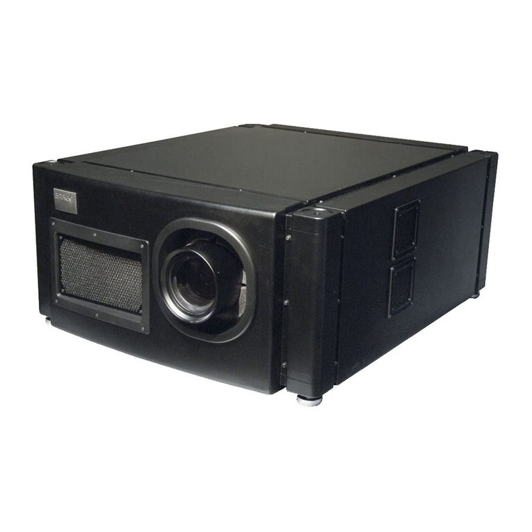
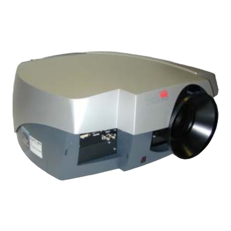
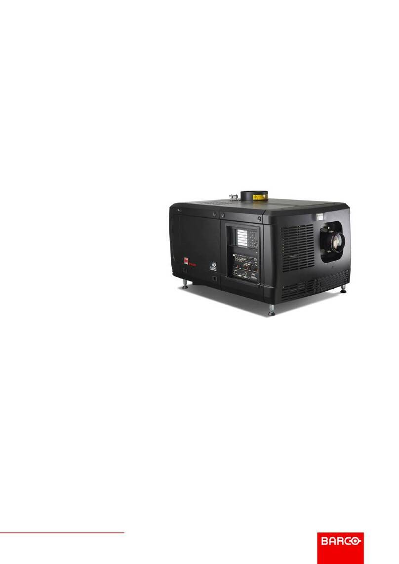
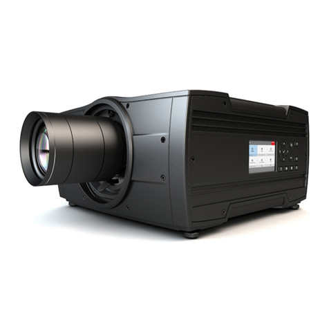
Barco R9001500 User manual

BARCOPROJECTIONSYSTEMS
Date :
18012000
OWNER'S MANUAL
ELM
G10
R9001500
R9001509
Art. No. :
R5976070

Due to constant research, the information in this manual is subject to change without notice.
Produced by BARCO NV, January 2000.
All rights reserved.
Trademarks are the rights of their respective owners.
BARCOn.v./ProjectionSystems
Noordlaan5
B-8520Kuurne
Belgium
Tel:+32/56/368211
Fax:+32/56/351651
Visite Barco at the web : http://www.barco.com
Printedin Belgium

i-1
Table of Contents
5976070 BARCOELM G10 150999
iTABLE OF CONTENTS
TABLE OF CONTENTS ........................................................................................................ I-1
SAFETY INSTRUCTION RELATED TO ELM PROJECTORS .............................................. 1
Warnings ........................................................................................................................................................... 1
To prevent personel injury 1
To prevent projector damage 1
Federal Communication Commission ................................................................................................................1
FCC statement 1
Note ................................................................................................................................................................... 1
PACKAGING AND DIMENSIONS ....................................................................................... 2-1
Projector Packaging ....................................................................................................................................... 2-1
Way of Packaging 2-1
Flightcase 2-1
Carton 2-1
To unpack : 2-1
Hint 2-1
Contents of the complete unit (box) : 2-1
Lamp Packaging ............................................................................................................................................. 2-2
Way of Packaging 2-2
Warning : 2-2
Lens Packaging .............................................................................................................................................. 2-2
Way of Packaging 2-2
Projector Case................................................................................................................................................ 2-2
Dimensions 2-2
INSTALLATION GUIDELINES .............................................................................................3-1
Installation Guidelines .................................................................................................................................... 3-1
Ambient Temperature Conditions 3-1
Humidity Conditions 3-1
Environment 3-1
Which screen type? 3-1
What image size? How big should the image be? 3-1
Projector Con igurations ................................................................................................................................. 3-2
Which configuration can be used 3-2
Positioning the Projector 3-2
Warning on Rotating the Projector 3-3
Safety Area around the Projector 3-4
Installation o the Lamp Casing ...................................................................................................................... 3-4
Lamp Casing Warnings 3-4
Installing the projection lamp 3-4
When transporting the projector : 3-5
Lenses............................................................................................................................................................ 3-6
Which Lens has to be selected 3-6
Available lenses 3-6
Re-adjusting the lamp position in the lamp casing 3-6
Lens formulas to calculate the projector distance 3-7
Installing the Projection Lens 3-7
Cleaning the lens 3-8
Battery installation in the RCU. ...................................................................................................................... 3-8
How is the battery delivered ? 3-8
How to install ? 3-8
Stacking two Projectors .................................................................................................................................. 3-9
Rigging points and Accessories. .................................................................................................................... 3-9
Optional Profile Sections 3-9
Fork lift Supports 3-10

i-2
Table of Contents
5976070 BARCOELM G10 150999
CONNECTIONS ................................................................................................................... 4-1
Power Connection to Projector ....................................................................................................................... 4-1
AC Power (mains) cord connection 4-1
Fuses 4-1
Switching ON 4-1
Lamp Run Time Indication 4-2
Lamp Runtime Warning 4-2
Switching to Stand-by 4-2
Switching Off 4-2
Input Source Connection ................................................................................................................................4-2
Input facilities 4-2
Input facilities, RCVDS05 or VS05 connected 4-3
Input module insertion into the projector ......................................................................................................... 4-3
Fixed RGB analog input (slot 1) ..................................................................................................................... 4-4
Fixed 5-Input Slot (slot 2) 4-5
Video/S-video Input Module ............................................................................................................................4-6
RGB Analog Input Module. ............................................................................................................................. 4-8
Component Input Module. ............................................................................................................................. 4-10
RGB3S / RG3sB Input Module. .................................................................................................................... 4-11
Communication Connections ........................................................................................................................ 4-13
Available communication connections : 4-13
RS232 Connections ...................................................................................................................................... 4-13
RS 232/422 input and RS232/422 output of the projector 4-13
Serial Digital Input (slot 5 & 6) ...................................................................................................................... 4-13
Communication port or communication with peripherals. ............................................................................. 4-14
Connecting a RCVDS 05 to the projector 4-14
Connecting a VS05 to the projector 4-14
Connecting an IR Remote Receiver to the projector 4-14
Trigger output ............................................................................................................................................... 4-14
GETTING STARTED ............................................................................................................ 5-1
Remote Control & Local Keypad .................................................................................................................... 5-1
Functionality 5-1
Terminology 5-2
Operating the Projector .................................................................................................................................. 5-3
Switching on 5-3
Lamp Run Time Indication 5-3
Lamp Run Time Warning 5-3
Switching to Stand-by 5-4
Switching Off 5-4
Quick Set Up Adjustments ............................................................................................................................. 5-4
Quick Language Change 5-4
Quick Lens Adjustment 5-4
Quick On Sceen Color change 5-5
Using the RCU ................................................................................................................................................ 5-6
Pointing to the reflective screen 5-6
Hardwired Remote Input 5-6
Hardwired to the XLR Input 5-7
Directly to the IR Sensors 5-7
Projector Address ........................................................................................................................................... 5-8
Why a projector address ? 5-8
Set up an Individual Projector Address 5-8
How to control the projector or projectors ? 5-8
Before using the RCU 5-8
Display the Projector Address on the Screen 5-8
How to Program an Address into the RCU ? 5-8
Controling the Projector .................................................................................................................................. 5-9
Input Selection 5-9
Picture Contols 5-9
The Pause key 5-9
The Stand-by key 5-9
START UP OF THE ADJUSTMENT MODE ........................................................................ 6-1
Adjustment Mode ........................................................................................................................................... 6-1
Start up 6-1


i-3
Table of Contents
5976070 BARCOELM G10 150999
Possible Paths 6-1
Password Protection 6-1
Entering the Password 6-1
Remark 6-2
Setting Up an Own Password 6-2
RANDOM ACCESS ADJUSTMENT MODE ........................................................................ 7-1
Random Access Mode ................................................................................................................................... 7-1
Starting up 7-1
Overview Flowchart 7-1
Picture Service ............................................................................................................................................... 7-2
Connecting a new Source 7-2
Start up the File Service 7-2
Possible File Manipulations 7-2
File Annotation 7-2
Load File ......................................................................................................................................................... 7-3
Start up the Load File 7-3
How to load a file ? 7-3
The image is not perfect ? 7-3
Edit File .......................................................................................................................................................... 7-4
What can be done with the Edit File menu ? 7-4
How to start up the EDIT menu ? 7-4
Which items can be adjusted ? 7-4
How to change the settings ? 7-4
How to find the correct values for the displayed item? 7-5
Rename a ile ................................................................................................................................................. 7-6
Start Up 7-6
How to change the characters ? 7-7
Copy a ile ...................................................................................................................................................... 7-7
Start Up 7-7
How to change the characters ? 7-7
Delete ............................................................................................................................................................. 7-8
Start Up 7-8
File Options .................................................................................................................................................... 7-8
Start Up 7-8
File Sort 7-8
File Load 7-8
Picture Tuning ................................................................................................................................................ 7-9
Start Up 7-9
Which Items can be Adjusted ? 7-9
CTI ON/OFF ................................................................................................................................................... 7-9
What is CTI ? 7-9
How to change the CTI setting ? 7-9
Note : 7-9
Color Temperature ........................................................................................................................................ 7-10
Start Up 7-10
Available color temperature : 7-10
Adjusting the Color Temperature 7-10
Custom Balance 7-10
Gamma ........................................................................................................................................................ 7-10
What can be adjusted ? 7-10
How to change the Gamma Value ? 7-11
Decoding EBU/IRE ....................................................................................................................................... 7-11
Note : 7-11
What can be done ? 7-11
How can it be selected ? 7-11
Dynamic Color Depth ................................................................................................................................... 7-11
Purpose : 7-11
To change the dynamic color depth value : 7-11
Noise Reduction ........................................................................................................................................... 7-12
Purpose : 7-12
To change the noise reduction value : 7-12
Input Balance ............................................................................................................................................... 7-12
Why adjusting the input balance ? 7-12
How to adjust the input balance ? 7-12
Geometry ..................................................................................................................................................... 7-13
To start up the Geometry functions : 7-13
Which geometry adjustments are possible ? 7-13
How can an adjustment be adjusted ? 7-13

i-4
Table of Contents
5976070 BARCOELM G10 150999
Shi t .............................................................................................................................................................. 7-13
What can be done ? 7-13
To start up the shift action : 7-13
Side Keystone .............................................................................................................................................. 7-14
What can be done ? 7-14
Aligning the keystone 7-14
Size .............................................................................................................................................................. 7-14
What can be done ? 7-14
To start up the size adjustment : 7-14
Blanking ....................................................................................................................................................... 7-15
What can be done ? 7-15
Available Blanking Adjustment 7-15
Adjusting the blanking 7-15
Aspect Ratio................................................................................................................................................. 7-16
What can be done? 7-16
Setting Up the Aspect Ratio 7-16
Options ......................................................................................................................................................... 7-16
Which Options are available within the Geometry menu ? 7-16
Changing the Geometry Options 7-16
INSTALLATION MODE ........................................................................................................ -1
Installation Mode ............................................................................................................................................8-1
Start Up 8-1
Input Slots ...................................................................................................................................................... 8-1
What can be done ? 8-1
To view or to change the input configuration : 8-1
Possible results for the input slots : 8-1
What if a switcher is connected to the projector ? 8-2
800 Peripheral ................................................................................................................................................ 8-2
What can be installed ? 8-2
Defining the Output module of the RCVDS05 8-2
Defining the Infrared Communication protocol 8-2
Con iguration ................................................................................................................................................... 8-3
What can be done ? 8-3
Set up the Correct Configuration 8-3
OSD color (On-Screen Display) ...................................................................................................................... 8-3
What can be done ? 8-3
How to change this color setting ? 8-3
No Signal ........................................................................................................................................................8-3
What will happen 8-3
Changing the Background Color 8-4
Changing the Shutdown Setting 8-4
Changing the Shutdown Time 8-4
Internal Patterns ............................................................................................................................................. 8-5
What can be done with these internal patterns ? 8-5
How to select an internal pattern ? 8-5
Note : 8-5
Lens Adjustments ........................................................................................................................................... 8-5
What can be done ? 8-5
Zoom/Focus/Shift/Tilt 8-6
How to Zoom/Focus ? 8-6
How to shift the image ? 8-6
How to tilt the image ? 8-6
Bridge up or down 8-7
SERVICE MODE .................................................................................................................. 9-1
Service Mode .................................................................................................................................................. 9-1
Start Up 9-1
Built-up of the service mode 9-1
Identi ication ................................................................................................................................................... 9-2
How to display the Identification screen ? 9-2
The information 9-2
Detailed description 9-2
Change Password .......................................................................................................................................... 9-3
How to enable or disable the password function ? 9-3
How to change the password ? 9-3

i-5
Table of Contents
5976070 BARCOELM G10 150999
Change Language ........................................................................................................................................... 9-4
Start Up 9-4
Change Projector Address .............................................................................................................................. 9-4
How to change that address ? 9-4
Entering the new projector address 9-4
Serial Communication .................................................................................................................................... 9-4
Start Up the Serial Communication menu 9-4
Setting up the Baud rate 9-5
Available Baud rates 9-5
RS422 Termination 9-5
BARCO logo ................................................................................................................................................... 9-6
What can be done ? 9-6
Reset Lamp Runtime ...................................................................................................................................... 9-6
When should the lamp run time be resetted 9-6
How to reset the lamp run time 9-6
Lamp Run Time History .................................................................................................................................. 9-6
What can be seen ? 9-6
How to get an overview of the different lamp run times ? 9-6
How to add or the change the settings ? 9-7
Available settings 9-7
Preset Input Balance ...................................................................................................................................... 9-7
Warning 9-7
How to start up ? 9-7
I2C diagnosis. ................................................................................................................................................. 9-8
What can be seen ? 9-8
How to start the I2C diagnosis ? 9-8
STANDARD SOURCE SET UP FILES .............................................................................. A-1

i-6
Table of Contents
5976070 BARCOELM G10 150999

1-1
Safety
5976070 BARCOELM G10 150999
1SAFETY INSTRUCTION RELATED TO ELM
PROJECTORS
Warnings
To prevent personel injury
The customer should never attempt to disassemble the lamp casing or to dispose of the lamp casing other than by returning it to BARCO
To prevent injuries and physical damage, always read this manual and all labels on the system before inserting the lamp casing or
connecting to the wall outlet, adjusting the projector
To prevent injuries, take note of the weight of the projector Minimum 4 persons are needed to carry the projector
NEVER look into the lens ! Due to the high luminance damage to the eye can happen
Before attempting to remove any of the projector's covers, you must turn off the projector and disconnect from the wall outlet
When performing set up work at a ceiling mounted projector, to prevent injury caused by falling objects or the system, set out a keep
out area
To prevent projector damage
If the Air Filters are not regularly replaced, the air flow inside the projector could be disrupted, causing overheating Overheating
may lead to the projector shutting down during operation
In order to ensure that correct airflow is maintained, and that the projector complies with Electro-Magnetic Compatibility requirements,
it should always be operated with all of it's covers in place
Ensure that nothing can be spilled on, or dropped inside the projector If this does happen, switch off and unplug the mains supply
immediately Do not operate the projector again until it has been checked by qualified service personnel
The projector must always be mounted in a manner which ensures free flow of air into its air inlets and unimpeded evacuation of
the hot air exhausted from its cooling system Heat sensitive materials should not be placed in the path of the exhausted air
Federal Communication Commission
FCC statement
This equipment has been tested and found to comply with the limits for a class A digital device, pursuant with Part 15 of the Federal
Communication Commision rules These limits are designed to provide reasonable protection against harmful interference when the
equipment is operated in a commercial environment This equipment generates, uses, and can radiate radio frequency energy and,
if not installed and used in accordance with the instruction manual, may cause harmful interference to radio communications Operation
of this equipment in a residential area may cause harmful interference, in which case the user will be responsible for correcting any
interference
Note
Read also safety instructions in seperate manual (R5975258)

1-2
Safety
5976070 BARCOELM G10 150999

2-1
PackagingandDimensions
5976070 BARCOELM G10 18012000
2
1
234
5
379
Pull
To open
PACKAGING AND DIMENSIONS
Projector Packaging
Way of Packaging
The projector can be packed in two different ways :
- in a flightcase or
- in carton
Flightcase
The projector is packed in a flightcase without the lamp casing and the lens
Carton
To provide protection during transportation, the projector is surrounded with foam, placed on a wooden palette and enclosed within
a sturdy fibreboard carton The package is then secured with banding and fastening clips
To unpack :
First release the two fastening clips and remove the banding Handle as shown in the drawing
As the projector is mounted on a wooden palette, turn out the 8 retaining bolts Use a 13 mm wrench to remove these bolts
Take the projector out of its shipping carton by handling by the carry handle and place it on the floor or table
Warning : Due to the projector's weight (143 5 kg), four people are required to lift the projector, one at each corner using the carry
handler The purchaser is reminded to use good practice in lifting the projector to avoid risk of back injury
Hint
Save the original shipping carton and packing material, they will be necessary if you ever have to ship your projector For maximum
protection, repack your projector as it was originally packed at the factory
Contents of the complete unit (bo ) :
- 1 BARCO ELM G10 (weight ± 143 5 kg, 316 lbs)
- 1 remote control unit RCU + 1 battery
- 1 power cable with outlet plug type IEC308 2p+G 32A/250V
- 1 owners manual
- 1 safety manual

2-2
PackagingandDimensions
5976070 BARCOELM G10 18012000
Lamp Packaging
Way of Packaging
The lamp casing is supplied as an individual item
The lamp can be packed in two different ways :
- in a flightcase or
- in carton
Warning :
Always transport the lamp in a vertical position !
Lens Packaging
Way of Packaging
Lenses are supplied as an individual item
They are packed in a carton
Projector Case
Dimensions
The dimensions are given in mm
25 4 mm = 1"
187 208
582
624
554
+20
0
524
+20
0
632
316
(nominal)154
113,5
70
45
291
(
)
410
()316
FRONT VIEW
REF
AIR IN AIR OUT
Shaft for lifting
fork-lift slots
Adjustable feet
Dual stack interlocking
IR-receiver
(both in front and at the rear
of the projector)
Protects sides
while turning over
the projector

2-3
PackagingandDimensions
5976070 BARCOELM G10 18012000
1420
155 475
760
745
785
1314
67
950 190,5
(nominal)
344
45
87,5
273
27,5
950
426
()
110
TOP VIEW
SIDE VIEW
REF
Dual stack Interlocking
Fasteners left and right
AIR OUT
AIR IN
Digital & Analog Inputs
Local Keypad
& Display
Mains Input &
Power Switch
Zone needed for Side Panel removal (Both Left ANDRight)

2-4
PackagingandDimensions
5976070 BARCOELM G10 18012000

3-1
InstallationGuidelines
5976070 BARCO ELM G10 18012000
3INSTALLATION GUIDELINES
Installation Guidelines
Ambient Temperature Conditions
Careful consideration of things such as image size, ambient light level, projector placement and type of screen to use are critical to
the optimum use of the projection system
Operation temperature :
Max ambient temperature : 40 °C (104°F)
Min ambient temperature : 0 °C (32°F)
The projector will not operate if ambient air temperature falls outside this range (0°C- 40°C) (32°F-104°F)
Storage temperature : -35 °C to + 65 °C (-25 6°F to 149°F)
Humidity Conditions
Storage : 0 - 98% RH Non-condensing
Operation : 0 - 95% RH Non-condensing
Environment
Do not install the projection system in a site near heat sources such as radiators or air ducts, or in a place subject to direct sunlight,
excessive dust or humidity Be aware that room heat rises to the ceiling; check that temperature near the installation site is not
excessive
Which screen type?
There are two major categories of screens used for projection equipment Those used for front projected images and those for rear
projection applications
Screens are rated by how much light they reflect (or transmit in the case of rear projection systems) given a determined amount
of light projected toward them The GAIN of a screen is the term used Front and rear screens are both rated in terms of gain The
gain of screens range from a white matte screen with a gain of 1 (x1) to a brushed aluminized screen with a gain of 10 (x10) or
more The choice between higher and lower gain screens is largely a matter of personal preference and another consideration called
the Viewing angle
In considering the type of screen to choose, determine where the viewers will be located and go for the highest gain screen possible
A high gain screen will provide a brighter picture but reduce the viewing angle
Regardless of the type of screen used, it is important that your screen is of sufficient height to display the images at the aspect ratio
intended to be used If you have insufficient height, you will have to reduce the overall image size in order to display the full image
on your screen
For more information about screens, contact your local screen supplier.
What image size? How big should the image be?
The projector is designed for projecting an image size : min 1 00m (3 3ft) to max depending on the ambient light conditions, with a
aspect ratio of 4 to 3

3-2
InstallationGuidelines
5976070 BARCO ELM G10 18012000
Projector Configurations
Which configuration can be used.
The projector can be installed to project images in four different configurations :
front/table,
rear/table,
front/ceiling or
rear/ceiling
Screen
PD
B
Floor
Projector
CD
SH
Optical axis projection lens
SH
SW
SIDE VIEW
BACK VIEW
Screen
TOP VIEW
SW
Floor
7DEOH7RSVLGHIDFLQJFHLOLQJ
A
CD = SH/2 + B - A
)URQW7DEOH
)URQW&HLOLQJ
5HDU7DEOH
5HDU&HLOLQJ
Positioning the Projector
The projector should be installed perpendicular with the screen on a distance PD and water leveled in both directions
Four mounting positions are possible
Be aware for the weight of the projector : 143 5 kg without projection lens
To carry the projector by the carry handler, 4 persons are needed
To carry the projector with a fork lift, special fork lift tools are available (see carry options)
Screen
PD
B
Floor
Projector
CD
SH
Optical axis projection lens
SH
SW
SIDE VIEW
BACK VIEW
Screen
TOP VIEW
SW
Floor
7DEOH7RSVLGHIDFLQJIORRU
A
CD = SH/2 + B +A - 554mm
Image 1
Image 2 Image 3

3-3
InstallationGuidelines
5976070 BARCO ELM G10 18012000
The mounting position shown in the above images are shown for a nominal lens position
When putting the projector on the 3 adjustable feet, use these feet to level the projector by turning these feet in or out
Definitions of the Abbreviation on drawings
B = Distance between ceiling and top of the screen or between floor and bottom of the screen
A = 344 mm , distance from the middle of the lens (in nominal position) to bottom side of the projector A shift of ± 20 mm up down
is possible
CD = Total distance between projector and ceiling or projector and floor
SW = Screen width
SH = Screen height (image height)
PD = Projector Distance, distance between screen and projector
Warning on Rotating the Projector
Screen
PD
B
Ceiling
Projector
CD
SH
Optical axis projection lens
SH
SW
SIDE VIEW
BACK VIEW
Screen
CEILINGVIEW
SW
Ceiling
&HLOLQJ7RSVLGHIDFLQJIORRU
A
CD = SH/2 + B - A
Screen
PD
B
Ceiling
Projector
CD
SH
Optical axis projection lens
SH
SW
SIDE VIEW
BACK VIEW
Screen
CEILING VIEW
SW
Ceiling
&HLOLQJ7RSVLGHIDFLQJFHLOLQJ
A
CD = SH/2 + B + A - 554mm
When the lamp casing is installed, it is not allowed to rotate the projector clockwise when facing the lenses An internal tilt switch
will provide to start up the projector
Correct way of rotating the projector, see image 6a
Image 4 Image 5
Image 6
Image 6a

3-4
InstallationGuidelines
5976070 BARCO ELM G10 18012000
Safety Area around the Projector
Make sure the projector is located so that the air inlets and outlets for the cooling system are not obstructed
Leave a safety areo of about 1 meter on the left and the right side of the projector
Installation o the Lamp Casing
Lamp Casing Warnings
Never transport the projector with the lamp casing installed
The lamp casing should always been transported in a vertical way to avoid damaging the lamp
Never attempt to disassemble the lamp from its housing or to dispose of it other than by returning it to BARCO Due to its high internal
pressure, the lamp may explode in either hot or cold state
Installing the projection lamp.
1 Unplug the projector from the wall outlet
2 On the input side of the projector, remove the side by turning the 3 bolts a quarter counter clockwise (image 8)
$,5,1
$
,5
287
6DIHW\DUHDIRUDLULQRXW
3 Flip the lower side of the plate a little and pull then downward to remove the plate
4 Take the lamp casing carefully out of its shipping box
Image 8
Image 7

3-5
InstallationGuidelines
5976070 BARCO ELM G10 18012000
5 Place the lamp casing on the optical base plate (image 9)
6 Push the lamp casing forward until the lamp slide fully into the projector (image 10 & 11) Both center pins (image 12) must match
both center holes
7 Secure the correct position by turning both bolts a quarter clockwise (image 13)
8 Reinstall the projector side panel
Remark :
No electrical connections have to be made while installing the lamp casing All connections are automatically made while inserting
the lamp casing
Note : While starting up the projector, the electronics detect if a lamp is installed If no lamp is installed, it is not possible to start up
the projector
When transporting the projector :
1 Switch the projector to stand by
2 Let cool down the projector for at least 15 minutes
3 Switch off the projector and unplug from the wall outlet
Image 13
Image 9 Image 10
Image 11
$
Image 12

3-6
InstallationGuidelines
5976070 BARCO ELM G10 18012000
4 On the input side of the projector, remove the side by turning the 3 bolts a quarter counter clockwise
5 Flip the lower side of the plate a little and pull then downward to remove the plate
6 Turn the retaining bolts of the lamp a quarter clockwise
7 Pull out the lamp casing Wear heat resistant gloves, the case can be hot
8 Pack the lamp casing into the lamp flightcase and transport it verticaly
Re-adjusting the lamp position in the lamp casing
With higher run times, the light output of the lamp will decrease, which results in a lower light output on the screen
This light output decrease can be compensated by readjusting the position of the lamp
As the projector has to be opened, this procedure has to be performed by qualified service technician
Handle as follow :
1 On the side of the inputs, turn the 3 retaining bolts a quarter counter clockwise
2 Flip the lower side a little backwards and take off the side cover
3 Loosen the nut A (image 14) on the back of the lamp casing (nutdriver 10)
4 Adjust the screw B (image14) with an allen key by turning a little clockwise until the maximum light output is reached
5 Fasten the nut on the back of the lamp casing to secure this position (nutdriver 10)
Lenses
Which Lens has to be selected.
1 Determine the required screen width
2 Determine the approximate position of the projector in the projection room with regard to the screen and measure the
projector-screen distance (PD)
3 Use the lens formulas to find the best corresponding PD with regard to the measured projector-screen distance for the required
screen width
The desired lens is determined (the order number is given in the tabel)
Available lenses
QLD lenses :
Name Lens Lenght mm (inch) Diameter mm (inch) Weight kg (lbs) Order number
QLD (1 5-2 0:1) 329 183 R9840130
QLD (2 0-2 5:1) 335 5 160 R9840140
QLD (2 5-4 0:1) 285 7 155 R9840150
QLD (4 0-7 0:1) 383 144 5 R9840160
QLD (1 2:1) 447 183 R9840120
Remark : When using these lenses with the ELM G10, the throw ratio is these for the ELM R12 x 1 25
LD lenses :
Name Lens Lenght mm (inch) Diameter mm (inch) Weight kg (lbs) Order number
LD (1 5-2 5:1) R9840090
LD (2 5-4 0:1) R9840270
LD (4 0-7 0:1) R9840280
Image 14
This manual suits for next models
1
Table of contents
Other Barco Projector manuals

Barco
Barco RLM-W14 User manual

Barco
Barco R9001250 User manual

Barco
Barco R9002129 User manual

Barco
Barco FLM R20+ Performer User manual

Barco
Barco FL-FS40 MKII User manual

Barco
Barco Galaxy 6 Classic+ Installation instructions

Barco
Barco XDX Series User manual

Barco
Barco iD H250 User manual

Barco
Barco FS33 IR WUXGA User manual

Barco
Barco IRIS 800 User manual

Barco
Barco r9002357 User manual

Barco
Barco iCon H250 User manual

Barco
Barco R6400 User manual

Barco
Barco F12 Series User manual

Barco
Barco FLM HD20 User manual

Barco
Barco F70 Series User manual

Barco
Barco UDX Series User manual

Barco
Barco UDX User manual

Barco
Barco R9828870 User manual

Barco
Barco Galaxy NH-12 User manual