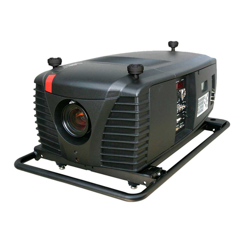
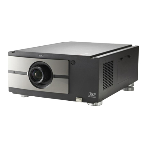
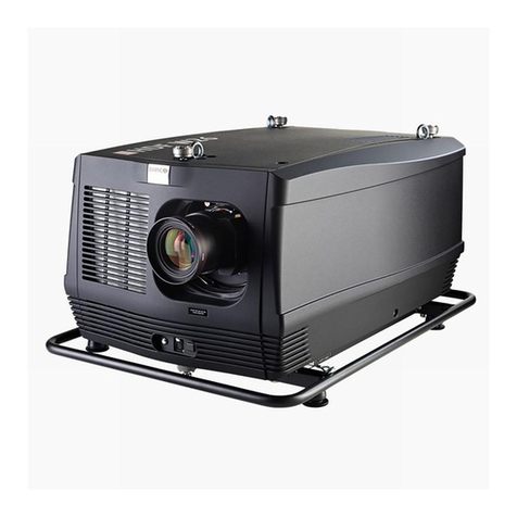
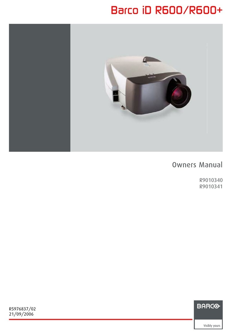
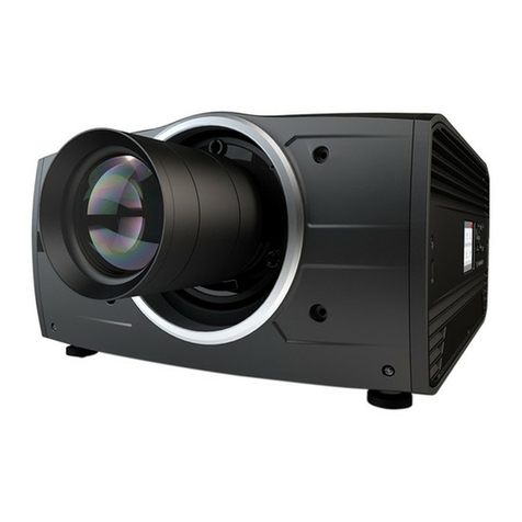
Barco RETRO DATA 2100LC User manual

OWNER'S MANUAL
RETRO BLOCK GRAPHICS
2100LC
R9031278

BARCO PROJECTION SYSTEMS
Rev 02
RETRO BLOCK GRAPHICS
OWNER'S MANUAL
Date : 250898
2100LC
R9031278
Art. No : R5975618A

BARCO nv/Projection Systems
Noordlaan 5
B-8520 Kuurne
Belgium
Tel : +32/56/368211
Fax : +32/56/351651
Visit Barco at the web : http://www.barco.com
Printed in Belgium
FEDERAL COMMUNICATION COMMISSION (FCC STATEMENT)
This equipment has been tested and found to comply with the limits of a class A digital device, pursuant to Part 15 of the FCC Rules. These
limits are designed to provide reasonable protection against harmful interference when the equipment is operated in a commercial environment.
This equipment generates, uses and can radiate radio frequency energy and, if not installed and used in accordance with the instruction
manual, may cause harmful interference to radio communications. Operation of this equipment in a residential area is likely to cause harmful
interference in which case the user will be required to correct the interference at his own expense.
Note :
The use of shielded cables is required to comply within the limits of Part 15 of FCC rules and EN55022.
* All the safety and operating instructions should be read before using this unit.
* The safety and operating instructions manual should be retained for future reference.
* All warnings on the equipment and in the documentation manuals should be adhered to.
* All instructions for operating and use of this equipment must be followed precisely.
Due to constant research, the information in this manual is subject to change without notice.
Produced by BARCO NV, August 1998.
All rights reserved.
Trademarks are the rights of their respective owners.

i-1
Table of Contents
5975618A RETRO BLOCK GRAPHICS 2100LC 280498
iTABLE OF CONTENTS
TABLE OF CONTENTS ......................................................................................................................................................... I-1
UNPACKING & DIMENSIONS ............................................................................................................................................. 1-1
Unpacking ...........................................................................................................................................................................................1-1
Projector Dimensions ..........................................................................................................................................................................1-1
Battery Installation in the RCU ............................................................................................................................................................ 1-2
INSTALLATION SET UP ....................................................................................................................................................... 2-1
LOCATION AND FUNCTION OF CONTROLS ..................................................................................................................... 3-1
Front Panel Terminology...................................................................................................................................................................... 3-1
Control Panel Terminology...................................................................................................................................................................3-2
POWER CONNECTION ...................................................................................................................................................... 4-1
Power (Mains) Cord Connection ........................................................................................................................................................ 4-1
Fuses ..................................................................................................................................................................................................4-1
Switching ON ......................................................................................................................................................................................4-1
Lamp Lifetime ...................................................................................................................................................................................... 4-2
Switching to Stand-by. ........................................................................................................................................................................4-2
Switching OFF ....................................................................................................................................................................................4-2
CONNECTIONS .................................................................................................................................................................. 5-1
Signal Input Connection to the Projector. ............................................................................................................................................5-1
Connecting a Video Source to the BNC Input (port 1) ..................................................................................................................... 5-1
Connecting a Video Source to the Cinch (RCA) Input (port 2) ..........................................................................................................5-2
Connecting a S-Video Source to the 4-pin mini DIN Input (port 3) ....................................................................................................5-2
Connecting a RGB Analog Source to Port 4 or 5 ...............................................................................................................................5-3
Connecting a Computer, e.g. IBM PC (or compatible), Apple Macintosh to the RS 232 Input of the Projector. ................................. 5-3
Set up of the Baud Rate for Communication with a Computer. .........................................................................................................5-4
Connecting a RCVDS 05 to the Projector. ..........................................................................................................................................5-4
Connecting a VS05 to the Projector. .................................................................................................................................................. 5-4
Connecting an IR Remote Receiver 800 to the Projector. ..................................................................................................................5-4
CONTROLLING ................................................................................................................................................................... 6-1
How to Use the RCU? ......................................................................................................................................................................... 6-1
Projector Address ...............................................................................................................................................................................6-1
How to Display a Projector Address? ................................................................................................................................................ 6-2
How to Program an Address into the RCU? .......................................................................................................................................6-2
Picture Controls with Direct Access. .................................................................................................................................................6-2
Sound Controls with Direct Access. .................................................................................................................................................. 6-3
The Pause Key....................................................................................................................................................................................6-3
The Mute Key ......................................................................................................................................................................................6-3
START UP OF THE ADJUSTMENT MODE .......................................................................................................................... 7-1
Adjustment Mode ................................................................................................................................................................................ 7-1
RANDOM ACCESS ADJUSTMENT MODE .......................................................................................................................... 8-1
Starting up the Random Access Adjustment Mode ............................................................................................................................8-1
File Service .........................................................................................................................................................................................8-2
Load File ..................................................................................................................................................................................8-2
Edit File ..................................................................................................................................................................................... 8-3
Rename File .............................................................................................................................................................................8-5
Copy File ..................................................................................................................................................................................8-5
Delete File(s) ........................................................................................................................................................................... 8-6
File Options ..............................................................................................................................................................................8-6
Picture Tuning ..................................................................................................................................................................................... 8-6
Sync SLOW/FAST ...................................................................................................................................................................8-7
Still Video .................................................................................................................................................................................8-7
Color Balance ..........................................................................................................................................................................8-7
Gamma ..................................................................................................................................................................................... 8-7
Audio Tuning ....................................................................................................................................................................................... 8-8
Volume, Balance, Bass and Treble .........................................................................................................................................8-8
Mute .........................................................................................................................................................................................8-8
Lock .........................................................................................................................................................................................8-8
Fade .........................................................................................................................................................................................8-8

i-2
Table of Contents
5975618A RETRO BLOCK GRAPHICS 2100LC 280498
Geometry ............................................................................................................................................................................................ 8-9
Shift .........................................................................................................................................................................................8-9
INSTALLATION MODE ......................................................................................................................................................... 9-1
Starting Up the Installation Mode .........................................................................................................................................................9-1
Configuration ....................................................................................................................................................................................... 9-1
OSD Color (On Screen Display) .........................................................................................................................................................9-1
Internal Patterns .................................................................................................................................................................................. 9-1
SERVICE MODE ................................................................................................................................................................ 10-1
Starting Up the Service Mode .......................................................................................................................................................... 10-1
Identification ..................................................................................................................................................................................... 10-2
Change Password ........................................................................................................................................................................... 10-3
Change Language ........................................................................................................................................................................... 10-3
Change Projector Address .............................................................................................................................................................. 10-3
Change Baudrate PC ....................................................................................................................................................................... 10-4
Reset Lamp Runtime ........................................................................................................................................................................ 10-4
Lamp Run Time History .................................................................................................................................................................... 10-4
Lamp Drive Mode ............................................................................................................................................................................. 10-5
Barco Logo ...................................................................................................................................................................................... 10-5
Preset Input Balance ........................................................................................................................................................................ 10-5
60 Hz Tracking ................................................................................................................................................................................. 10-6
I2C Diagnosis ................................................................................................................................................................................... 10-6
APPENDIX A: STANDARD SOURCE SET UP FILES ........................................................................................................... A-1
APPENDIX B: LENSES ........................................................................................................................................................ B-1
Focusing the Lens ............................................................................................................................................................................. B-1
Lens Cleaning Procedure .................................................................................................................................................................. B-1
Lenses ............................................................................................................................................................................................... B-2
APPENDIX C: SOURCE NUMBERS 90 - 99 ...................................................................................................................... C-1
APPENDIX D: REPLACING DUST FILTERS AND MOUNTING OF ACCESSORIES .......................................................... D-1
Replacing Dust Filters ........................................................................................................................................................................ D-1
Mounting of Accessories................................................................................................................................................................... D-2

1-1
Unpacking & dimensions
5975618A RETRO BLOCK GRAPHICS 2100LC 280498
1UNPACKING & DIMENSIONS
Unpacking
To open banding, pull on the clip as shown here:
Take the projector out of its shipping carton and place it on a table. For transportation, the projector is mounted
on a wooden board with 3 bolts (M5). Use a 8 mm wrench to remove these bolts.
Projector Dimensions
(units: mm)
Save the original shipping carton and packing material, they will come in handy if you ever have to ship your projector.
For maximum protection, re-pack your projector as it was originally packed in the factory. (see drawing below)
Contents of the shipped box:
-1 RETROBLOCK GRAPHICS 2100LC
-1 remote control unit + 1 9V battery
-1 power cable with outlet plug type ANSI 73.11.
-3 plastic supporting feet
-4 plastic handles
-1 owners manual
- 1 installation manual
- 1 safety manual
195,4
605
227 70243
289,5
CENTER OFGRAVITY
177
23
1.2 lens
160,1
637,5
B
65,5
404,6
CD194
F
125,4
E
G
M5
With 0,8 lens With 1,2 lens
A 137 134
B 302 329,8
C 296,6 268,8
D 108 135,8
E 121,6 129,6
F 223 215
G 4 12

1-2
Unpacking & dimensions
5975618A RETRO BLOCK GRAPHICS 2100LC 280498
Battery Installation in the RCU
A battery (not yet installed to save the battery life time) is delivered inside the plastic bag with
the power cord. Before using the RCU, start the battery installation procedure.
Remove the battery cover on the backside of the remote control by pushing the indicated handle
a little to the bottom of the RCU. Lift up the top side of the cover at the same time (fig.1)
Insert the new 9 V battery in the lower compartment and connect the battery to the contact plate.
Put the cover back on.
Note: the projector address has to be programmed on the RCU before using the RCU (see
chapter 'Controlling').
Fig. 1
Contact plate
Battery
'Insert card RCU' (to be cut out
onthelastpageofthismanual)

2-1
Installation Set Up
5975618A RETRO BLOCK GRAPHICS 2100LC 280498
2
)URQW7DEOH
)URQW&HLOLQJ
5HDU7DEOH
5HDU&HLOLQJ
INSTALLATION SET UP
To change the Configuration, enter the adjustment mode by pushing ADJUST or ENTER.
Highlight Installation by pushing the control disk forward or backward and press ENTER
to select. The installation menu will be displayed.
ADJUSTMENT MODE
Select a path from below :
RANDOM ACCESS
INSTALLATION
SERVICE
Source 01
The actual selected configuration will be highlighted.
Push the control disk forward or backward to select the corresponding configuration
with regard to the projector environment. Press ENTER to confirm your selection.
ENTER displays the Installation menu.
EXIT returns to operational mode.
ENTER to confirm the selection.
EXIT returns to the installation menu.
ADJUST returns to operational mode.
Highlight Configuration by pushing the control disk forward or backward and press
ENTER to select. The configuration menu will be displayed.
ENTER displays the Configuration menu.
EXIT returns to the path selection menu.
ADJUST returns to operational mode.
Select with êor é
then <ENTER>
<EXIT> to return.
¨CONFIGURATION
FRONT/TABLE
FRONT/CEILING
REAR/TABLE
REAR/CEILING
INSTALLATION
CONFIGURATION
OSD COLOR
INTERNAL PATTERNS
INSTALLATION
Select with êor é
then <ENTER>
<EXIT> to return.
Select with êor é
then <ENTER>
<EXIT> to return.
The RETRO BLOCK GRAPHICS 2100LC can be installed to project images in four different
configurations: front/table, front/ceiling, rear/table and rear/ceiling. It is however mostly
used in a retro-configuration (rear/...).

3-1
Location and Function of Controls
5975618A RETRO BLOCK GRAPHICS 2100LC 280498
3
01 A/C Power Switch : '1' = ON, '0' = OFF.
LOCATION AND FUNCTION OF CONTROLS
Front Panel Terminology
09 Port 4 : RGB H/C V Input: RGB analog input with standard sync
on 5 BNC connectors. The sync can be sync on green, composite
sync, separate sync (H & V) or 3 level sync.
10 Port 5: RGB H/C V Input: RGB analog input with standard sync
on 5 BNC connectors. The sync can be sync on green, composite
sync, separate sync (H & V) or 3 level sync.
11 Diagnostics Code : a) Source number
b) Error code : a two digit error code
is displayed when there is a malfunc-
tion inside the projector.
12 IR Receiver : Receiver for control signals transmitted from the
RCU.
13 IR-Acknowledged : (green LED) IR signals are recognized.
IR-Received : (red LED) IR signals are received without knowing
for which projector.
14 Mechanical Shift:
Upper bolt: Allows a limited vertical shift of the image
Lower bolt: Allows a limited horizontal shift of the image
15 RS 232 IN : To allow communication with external computer, e.g.
IBM PC or compatible, Macintosh ...
03 Audio Out : 2 x Cinch (RCA) stereo audio output.
04 Audio Select LED's : Lit up (next to each audio input) when
AUDIO IN A/B/C or AUDIO OUT are selected.
05 Audio In : 3 audio inputs on 2 Cinch (RCA) connectors for audio
(L-R).
06 Port 3 : S-Video on 4-pin mini-DIN connector. Separate Y/C
(luma-chroma) signal inputs for higher quality playback of Super
VHS signals.
07 Port 2 : Video Input on Cinch (RCA) connector. Allows a video
tape recorder, video camera, color receiver/monitor, etc. having
a video line output to be connected to the projector.
08 Port 1 : Video Input (composite video) on BNC connector.
Allows a video tape recorder, video camera, color receiver /
monitor, etc. having a video line output to be connected to the
projector.
$8',2,1&
$8',2,1%
$8',2,1$
9,'(2
9,'(2
69,'(2
5*%+&9
5*%+&9
/5 /5 /5 /5
,5
55
**
%%
+& +&
9
9
3257
3257
3257
32573257
5628756,1
&2003257
&75/
hard wire remote
$8',2287
02 A/C Power Input : Switchable between 120 Vac and 230 Vac
(refer to installation manual.)

3-2
Location and Function of Controls
5975618A RETRO BLOCK GRAPHICS 2100LC 280498
COLOR
PHASE
SHARPN TINT BRIGHTN
STANDBY
ENTER
TEXT
EXIT
PAUSE
&2175$67
+
+
+
+
+
0
9
78
6
5
4
3
2
1
+
BALANCE
+
+
VOLUME
+
BASS
+
CONTRAST
TREBLE
BRIGHTNESS
COLOR
TINT
SHARPNESS
ADJ
FREEZE
MUTE PHASE
EXIT
PAUSE TEXT
STBY
ENTER
B
B
B
B
B
B
B
B
B
B
ADDR
HELP
16 RS 232 OUT : Used to connect to next projector, RS 232 IN plug
(communication link for PC or MAC to the next projector).
17 Communication port : Allows communication with the 800
series peripherals.
18 CTRL : Remote input for hard wired remote control.
19 Lens Mounting : Projected picture output.
Control Panel Terminology
a. Local Keypad
The keypad is located on the top of the projector.
b. Remote Control
20 IR Receiver : IR receiving sensor.
21 Discrete Off-axis: Mechanical adaptation of lens-mounting to
chosen internal conversion-kit. Range: from on-axis projection
to 10° off-axis for both 0.8 & 1.2 lens.
22 Projector Mode Indication: Indicates the status of the projec-
tor.
No light: Power switch is not pressed.
Red light: Power switch is pressed, projector in stand by mode.
Green light: Projector in operational mode.
RBLG 2100

3-3
Location and Function of Controls
5975618A RETRO BLOCK GRAPHICS 2100LC 280498
Terminology
01 RC Operating Indication : Lights up when a button on the
remote control / local key-pad is pressed. (This is a visual
indicator to check the operation of the remote control)
02 STBY : Stand by button :
- To initiate remote power up operation
- To stop projection without main power off.
03 Control Disc : To make menu selections when in the adjustment
mode. Also allows to increment or decrement an adjustment in
the adjustment mode.
Control Disc Up = up arrow in the menus
Control Disc Down = down arrow in the menus
Control Disc to the Right = arrow to the right on the menus
Control Disc to the Left = arrow to the left on the menus
04 EXIT : To leave the adjustment mode or to scroll upwards when
in the adjustment mode.
05 ENTER : To start up the adjustment mode or to confirm an
adjustment or selection in the adjustment mode.
06 PAUSE: To blank theimage,pressPAUSE. The image disappears
but full power is retained for immediate restarting.
07 TEXT : When adjusting one of the image controls during a
meeting, the displayed bar scale can be removed by pressing
'TEXT' key first. To re-display the bar scale on the screen, press
'TEXT' key again. 'TEXT' key is only active in operational mode.
When 'TEXT' is off, no warning message will be displayed.
08 Picture Controls : Use these buttons to obtain the desired level
(see also 'Controlling') for each picture function.
09 PHASE : Used to remove instability of the image.
10 Digit Buttons : Direct input selection.
11 ADJ. : Adjust key, to enter or exit the adjustment mode.
12 Address Key (recessed key), to enter the address of the
projector (between 0 and 9). Press the address key, followed
by pressing one digit button between 0 and 9.
14 Help : Not Active.
15 FREEZE : To freeze the projected image, the picture will freeze
but the sound will continue.
13 Mute : Press this key to temporarily turn off the sound. To return
to its previous level, press the key once again. (only valid when
external audio system is connected to audio out)
16 Sound Controls : Use these buttons to obtain the desired sound
level. (only valid when external audio system is connected to
audio out)

Power Connection
4-1
5975618A RETRO BLOCK GRAPHICS 2100LC 280498
4
Stand by button
-
+
-
+
-
+
-
+
-
+
0
9
78
65
43
21
ENTER
PAUSE
-
+
PHASE
FREEZTEXT
EXITADJ
ADDR
STBY
SHARPNESS
TINT
COLOR
BRIGHTNESS
CONTRAST
MUTE
-
+
BALANCE
-
+
TREBLE
-
+
VOLUME
-
+
BASS
HELP
?
COLOR
PHASE
SHARPN TINT BRIGHTN
STANDBY
ENTER
TEXT
EXIT
PAUSE
&2175$67
POWER CONNECTION
Fuses
Warning
For continued protection against fire hazard :
- replace with the same type of fuse.
- refer replacement to qualified service personnel
Fuse type : T16 AH/250V Order no. : B370076
Power (Mains) Cord Connection
Use the delivered power cord to connect your projector to the wall
outlet. Plug the female power connector into the male connector at
the front of the projector.
The power voltage for the projector is indicated on the identification
plate on the front of the projector.
The projector input voltage is internally switchable between 230 Vac
and 120Vac. Consult a qualified service technician to adapt the input
voltage to the correct voltage on the wall outlet. When the projector
leaves the factory, it is pre-configured to operate on a mains (power)
input of 120 Vac.
This projector may be connected to an IT-power system.
$8',2,1&
$8',2,1%
$8',2,1$
9,'(2
9,'(2
69,'(2
5*%+&9
5*%+&9
/5 /5 /5 /5
,5
55
**
%%
+& +&
9
9
3257
3257
3257
32573257
5628756,1
&2003257
&75/
hard wi re remote
$8',2287
$8',2
,1
&
$8',2
,1
%
$8',2
,1
$
/5 /5 /5 /5
$8',2
287
$8',2,1&
$8',2,1%
$8',2,1$
9,'(2
9,'(2
69,'(2
5*%+&9
5*%+&9
/
5 /
5 /
5/5
,5
55
**
%%
+& +&
9
9
3257
3257
3257
32573257
$8',2287
Projector mode indication lamp
$8',2,1&
$8',2,1%
$8',2,1$
9,'(2
9,'(2
69,'(2
5*%+&9
5*%+&9
/5 /5 /5 /5
,5
55
**
%%
+& +&
9
9
3257
3257
3257
32573257
5628756,1
&2003257
&75/
hard wi re remote
$8',2287
Switching ON
Use the power switch to switch on.
When '0' is visible, the projector is switched OFF.
When '1' is visible, the projector is switched ON.
When switching on with the power switch, the projector starts in the
stand by mode.
The projector mode indication lamp is red.
To start image projection, press the 'Stand by' button on the local
keypad or on the remote control.
The projector mode indication lamp will be green.

Power Connection
4-2 5975618A RETRO BLOCK GRAPHICS 2100LC 280498
Switching to Stand-by.
When the projector is running and you want to go to stand-by, press
the stand-by key.
Caution : Before powering down the projector, switch the projector
to stand-by and let the projector lamp cool down until the fans stop
blowing (or for at least 15 minutes).
Switching OFF
To switch off:
- Press first STANDBY key and let the projector lamp cool down until
the fans stop blowing (or at least 15 minutes).
- Switch off the projector with the power switch.
REMAINING LAMP RUN TIME: 20 hours
Lamp Lifetime
Before the end of lamp life, the following message will be scrolling
over the screen several times.
It will be displayed at the following points in time:
end of lamp life - 500 hours
end of lamp life - 100 hours
end of lamp life - 50 hours
end of lamp life
Press EXIT to remove the message.
The total lamp lifetime of the lamp for a safe operation is 4000 hours
max. in normal mode and 2000 hours max. in boost mode.
Do not use it longer. Always replace with a same type of lamp. Call
a BARCO authorized service technician for lamp replacement.
Warning : Using a lamp longer than end of lifetime
is dangerous, the lamp could explode!
Note: Switching the projector OFF and ON again,
adds 45 minutes to the lamp run time.

5-1
Connections
5975618A RETRO BLOCK GRAPHICS 2100LC 280498
5
$8',2,1&
$8',2,1% $8',2,1$
9,'(2
9,'(2
69,'(2
5*%+&9
5*%+&9
/5 /5
/5 /5
,5
55
**
%%
+& +&
99
3257
3257
3257
32573257
$8',2287
TV tuner, e.g.
TVDM 40 stereo
VCR
Audio amplifier
CONNECTIONS
Signal Input Connection to the Projector.
The following sources can be connected to the projector :
- Composite Video
- S-Video
- RGBS or RGsB
- RGBHV
- RGB3S or RG3sB
Connecting a Video Source to the BNC
Input (port 1)
Composite video signals from a VCR, OFF air signal decoder, etc. ...
1 x BNC 1.0Vpp ± 3 dB
Connect the audio input signals to the AUDIO A input when the audio
lock is OFF (see also chapter "Controlling")
Video Input Selection :
Press digit button 1 on the RCU.
(*) RGB with separate sync (composite or hor. or vert. sync), sync
signals on green, tri-level sync or composite video as sync signal.
Source input Input type Digit button
on RCU Audio Input
(lock is off)
port 1 Comp. Video 1 A
port 2 Comp.Video 2 B
port 3 S-Video 3 C
port 4 RGB (*) 4 B
port 5 RGB (*) 5 C
Note : When using a RCVDS05 or VS05, the input configuration of the
projector must be as follows :
Video from RCVDS05 or VS05 èport 1
S-Video from RCVDS05 or VS05 èport 3
RGB from RCVDS05 èport 4

5-2
Connections
5975618A RETRO BLOCK GRAPHICS 2100LC 280498
$8',2,1&
$8',2,1%
$8',2,1$
9,'(2
9,'(2
69,'(2
5*%+&9
5*%+&9
/5 /5
/5 /5
,5
55
**
%%
+& +&
9
9
3257
3257
3257
32573257
$8',2287
S-VHS VCR
Audio amplifier
$8',2,1&
$8',2,1%
$8',2,1$
9,'(2
9,'(2
69,'(2
5*%+&9
5*%+&9
/5 /5
/5 /5
,5
55
**
%%
+& +&
9
9
3257
3257
3257
32573257
$8',2287
TV tuner, e.g.
TVDM 40 stereo
VCR
Audio amplifier
Connecting a Video Source to the Cinch
(RCA) Input (port 2)
Composite video signals from a VCR, OFF air signal decoder, etc. ...
1 x Cinch (RCA) 1.0Vpp ± 3 dB
Connect the audio input signals to the AUDIO B input when the audio
lock is OFF (see also chapter "Controlling")
Video input selection :
Press digit button 2 on the RCU.
Connecting a S-Video Source to the 4-pin
mini DIN Input (port 3)
Separate Y-luma/C-chroma signals for higher quality playback of
Super VHS signals..
1 x 4 pins plug
pin configuration :
1ground luminance
2ground chrominance
3luminance 1.0 Vpp ± 3 dB
4chrominance 282 mVpp ± 3 dB
Connect the audio input signals to the AUDIO C input when the audio
lock is OFF (see also chapter "Controlling")
S-Video input selection :
Press digit button 3 on the RCU.

5-3
Connections
5975618A RETRO BLOCK GRAPHICS 2100LC 280498
$8',2,1&
$8',2,1%
$8',2,1$
9,'(2
9,'(2
69,'(2
5*%+&9
5*%+&9
/5 /5
/5 /5
,5
55
**
%%
+& +&
9
9
3257
3257
3257
32573257
$8',2287
BARCO interface
To audio amplifier
To next projector
RS232 IN
5628756,1
&2003257
&75/
hard wire remote
RS232 connection
Connecting a RGB Analog Source to Port
4 or 5
RGB analog input terminals with automatic sync detection. Sync can
be separate Horizontal and Vertical sync (RGB-HV), Composite sync
(RGB-S), Sync signals on green(RGsB), Composite tri-level sync
(RGB-3S), Tri-level sync signals on green (RG3sB) or RGB with
composite video as sync signal.
Always use an interface when a computer and local monitor have
to be connected to the projector. Recommended interfaces to be
applied:
Universal analog interface.
Order number : R9826100.
RGB 120 MHz analog interface.
Order number : R9826570.
VGA interface (only for low resolution sources)
Order number 120V : R9828079.
Order number 230V : R9828070
MAC interface
Order number 120V : R9828059
Order number 230V : R9828050
MAGIK interface
Order number 120V : R9828129
Order number 230V : R9828120
RGBS/RGsB analog : 5 x BNC
Red : 0.7 Vpp ± 3 dB
Blue : 0.7 Vpp ± 3 dB
Green : 0.7 Vpp ± 3 dB
1 Vpp ± 3 dB if sync on green
Vert. sync : 1 Vpp to 4 Vpp ± 3 dB
Hor. sync / Composite sync : 1 Vpp to 4 Vpp ± 3 dB
All inputs are non-floating inputs.
All input signals are 75 ohm terminated.
Connect the possible audio input signals for input 4 to the AUDIO B
input when the audio lock is OFF and for source 5 to the AUDIO C
input when the audio lock is OFF (see also chapter "Controlling")
RGB Input Selection :
For source 4, press digit button 4 on the RCU.
For source 5, press digit button 5 on the RCU.
Connecting a Computer, e.g. IBM PC (or
compatible), Apple Macintosh to the RS
232 Input of the Projector.
The projector has a RS232 port that allows it to communicate with a
computer.
Applications : remote control and data communications.
a) remote control :
- easy adjustment of projector via IBM PC (or compat-
ible) or MAC connection.
- allow storage of multiple projector configurations and
set ups.
- wide range of control possibilities.
- address range from 0 to 255.
b) data communications :
- sending data to the projector or copying the data from
the projector to a hard memory device.

5-4
Connections
5975618A RETRO BLOCK GRAPHICS 2100LC 280498
3URMHFWLRQ5RRP &RQWURO5RRP
,55HPRWH
5HFLHYHU
Projector
Communication cable
Set Up of the Baud Rate for
Communication with a Computer.
See 'Change Baudrate PC' in chapter 'Service mode'.
Connecting a RCVDS 05 to the Projector.
- Up to 20 inputs with the RCVDS 05 and 90 inputs when RCVDS's
are linked via the expansion module.
- Serial communication with the projector.
- Remote control buttons on the RCVDS to control the projector
(source selection and analog settings).
- The selected source number will be displayed on a 2 digit display
and the selected input module will be indicated with a LED on the
rear.
For more information about the use of the RCVDS 05, consult the
Owner's Manual, order number : R5975765.
Connecting a VS05 to the Projector.
The VS05 can switch up to 5 Composite Video sources, 3 Super
Video sources and 1 RGB analog or component video source to the
projector. In addition, the audio signal related to the source, can be
switched to an audio amplifier. To do so, connect the audio signal
of the source to the Audio Input A.
Order number : R9827890
For more information about the use of the VS05, consult the VS05
Owner's Manual, BARCO order number : R5975245.
Connecting an IR Remote Receiver 800 to
the Projector.
This infrared receiver unit makes it possible to control the projector
from another room.
There is a communication line cable between the IR receiver and the
projector or the RCVDS. The control information from the RCU can
now be sent to the IR Remote Receiver 800.
The IR Remote Receiver 800 displays the selected source on a 7-
segment display.
Order number : R9827515.
The following connections have to be made between the RCVDS and
the projector :
Video to port 1
S-Video to port 3
RGB to port 4
Audio signal to audio input A

Controlling
6-1
5975618A RETRO BLOCK GRAPHICS 2100LC 280498
6CONTROLLING
The projector can be controlled with
a. the RCU
b. the hardwired RCU (cable is not included)
c. the local keypad.
Controlling the projector with the RCU and the hardwired RCU is equal.
How to Use the RCU?
a) Point the front of the RCU to the reflective screen surface.
Ceiling
Screen
IR sensor
RCU
b) RCU used in a hardwired configuration.
Plug one end of the remote cable in the connector on the bottom of
the RCU and the second side in the connector in the front panel of
the projector labelled 'CTRL'.
c) Point the front of the RCU directly at one of the IR sensors of the
projector.
When using the wireless remote control, make sure you are within
the effective operating distance (30m (100ft) in a straight line). The
remote control unit will not function properly if strong light strikes the
sensor window or if there are obstacles between the remote control
unit and the projector IR sensor.
Projector Address
a. Software Set Up of the Projector Address.
See 'Change projector address' in chapter 'Service mode'.
Every projector requires an individual address between 0 and 255
which can be set in the Service mode. Only projectors with
addresses between 0 and 9 can be controlled with the RCU.
b. How to Control the Projector or Projectors.
The projector's address may be set to any value between 0 and 255.
When the address is set, the projector can be controlled now :
- RCU for addresses between 0 and 9.
- Computer, e.g. IBM PC (or compatible), Apple MAC, etc. for
addresses between 0 and 255.
Note : A projector will respond to a RCU set to an address of '0'
regardless of what address is set in the projector itself.
c. Using the RCU.
Before using the RCU, it is necessary to enter the projector address
into the RCU (only when that address is between 1 and 9). The
projector with the corresponding address will listen to that specific
RCU.
When address 0, 'zero address' is programmed into the RCU, every
projector, without exception will listen to the commands given by this
RCU.
$8 ',2,1& $8 ', 2 ,1 % $8' ,2,1 $
9,'( 2
9,'( 2
69, ' (2
5* %+& 9
5*%+ & 9
/ 5 / 5 / 5 /5
,5
55
**
% %
+& +&
9 9
3257
3257
3257
32573257
5628756,1 &2003257 &75/
hard wire r emo te
$8 ',228 7
$8',2, 1 & $8',2 ,1 % $8', 2,1 $
9,'(2
9,'(2
69,'(2
5*%+&9
5*%+&9
/ 5 / 5 / 5 / 5
,5
5 5
**
% %
+& +&
9 9
3 257
3 257
3 257
32573 257
56 28756 , 1 &200 325 7 &75/
hard wi re remo te
$8',22 87 $8',2 ,1 & $8', 2 ,1% $8',2, 1$
9,'(2
9,'(2
69,'(2
5*%+&9
5*%+&9
/ 5 / 5 / 5 / 5
,5
5 5
**
% %
+ & + &
9 9
3 257
3257
3 257
3 2573257
56 28756, 1 &2 00325 7 &75/
ha r dw ire re mote
$8',22 87
RCU
45° 45°
RCU
45° 45°

Controlling
6-2 5975618A RETRO BLOCK GRAPHICS 2100LC 280498
How to Display a Projector Address?
Press the ADDRESS key (recessed key on the RCU) with a pencil.
The projector's address will be displayed in a 'Text box'. This text box
disappears after a few seconds.
To continue using the RCU, it is necessary to enter the same address
with the digit buttons (address between 0 and 9). For example : if
the Address key displays projector address 003, then press "3" digit
button on the RCU to set the RCU's address to match the projector's
address. Do not press digit 003. This will address the remote to '0'
and control all projectors in the room.
How to Program an Address into the
RCU?
Press the ADDRESS key (recessed key on the RCU) with a pencil and
enter the address with the digit buttons. That address can be any
digit between 0 and 9.
Picture Controls with Direct Access.
When an image control is pressed, a text box with a bar scale, icon
and function name of the control, e.g. 'brightness...' appears on the
screen (only if text is ON). See example screen. The length of the
bar scale and the value of the numeric indication indicate the current
memory setting for this source. The bar scale changes as the + or
- buttons of the control on the RCU are pressed or the + or - buttons
on the local keypad.
Brightness Control
A correct 'brightness' setting is important for good image reproduc-
tion.
Use the + button for a higher brightness.
Use the - button for a lower brightness.
Contrast Control
A correct 'contrast' setting is important for good image reproduction.
Adjust the contrast to the level you prefer, according to room lighting
conditions.
Use the + button for a higher contrast.
Use the - button for lower contrast.
Color Saturation
Color saturation is only active for Video and S-Video. Adjust the color
intensity of the picture.
Use the + button for richer colors.
Use the - button for lighter colors.
Tint Control
Tint is only active for Video and S-Video when using the NTSC 4.43
or NTSC 3.58 system.
Use the + button
Use the - button.
Sharpness Control.
Use the + button for a sharper picture.
Use the - button for a softer picture.
Phase Control
Use the Phase key to adjust the phase until stable representation of
fine picture details is reached.
BRIGHTNESS
0255
PROJECTOR ADDRESS
001

Controlling
6-3
5975618A RETRO BLOCK GRAPHICS 2100LC 280498
Sound Controls with Direct Access.
VOLUME
044
Volume Control
Volume control adjusts the volume.
Use the + button for a higher volume.
Use the - button for a lower volume.
Bass Control
Bass control adjusts the bass level (low tones).
Use the + button for more low tones.
Use the - button for less low tones.
Treble Control
Treble control adjusts the treble level (high tones).
Use the + button for more high tones.
Use the - button for less high tones.
Balance Control
The balance control adjust the sound level between the left and the
right speaker.
Use the + button for a higher sound level on the right speaker than
on the left one.
Use the - button for a higher sound level on the left speaker than on
the right one.
The Pause Key
When the Pause key is pressed, the image projection is stopped but
the projector remains with full power for immediate restart. The
sound is not interrupted.
To restart the image reproduction :
- press pause key,
- press exit key or
- select a source number.
The Mute Key
When the Mute key is pressed, the sound reproduction is stopped.
The image is still displayed.
To restart the sound reproduction, press the Mute key again.
When a sound control is pressed, a text box with a bar scale, icon
and function name of the control, e.g. 'volume...' appears on the
screen (only if text is ON). See example screen. The length of the
bar scale indicates the current memorized setting for this source. The
bar scale changes as the + or - buttons of the control are pressed.
The picture controls can only be adjusted with the RCU.
(Only valid with an external audio system connected to the audio
output)
Other manuals for RETRO DATA 2100LC
1
Table of contents
Other Barco Projector manuals

Barco
Barco F12 Series User manual

Barco
Barco ELM G10 User manual

Barco
Barco R5975236 User manual

Barco
Barco Galaxy 4 Long Life+ R9040355 User manual

Barco
Barco UDM Series User manual

Barco
Barco UDX Series User manual

Barco
Barco FLM HD18 User manual

Barco
Barco DICOM THEATER User guide

Barco
Barco R9001140 User manual

Barco
Barco FLM HD14 User manual