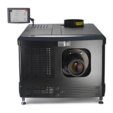
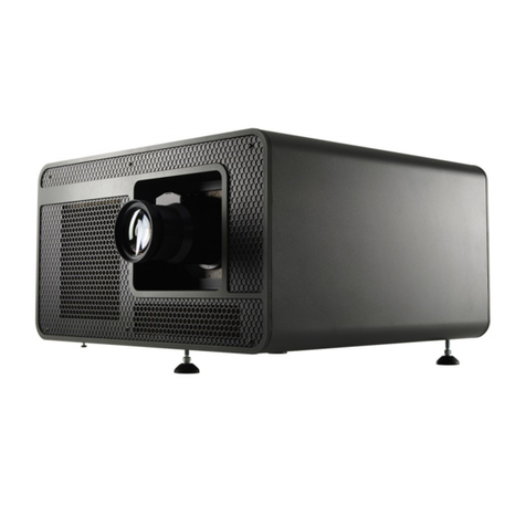
Barco VISION 701 MULTIMEDIA User manual

BARCO PROJECTION SYSTEMS
OWNER'S MANUAL
BARCO PROJECTION SYSTEMS
R9000748
OWNER'S MANUAL
R9000748
Art.No.
R5975238A
Date:
200697
Date:
200697 Art.No.
R5975238A
VISION
701 MULTIMEDIA VISION
701 MULTIMEDIA
Rev. :
00
Rev. :
00

Due to constant research, the information in this manual is subject to
change without notice.
Produced by BARCO NV, June 1997.
All rights reserved.
Trademarks are the rights of their respective owners.
Printed in Belgium
Due to constant research, the information in this manual is subject to
change without notice.
Produced by BARCO NV, June 1997.
All rights reserved.
Trademarks are the rights of their respective owners.
PrintedinBelgium

R5975238A BARCOVISION 701 MULTIMEDIA 200697
TABLE OF CONTENTS
1
TABLE OF CONTENTS
R5975238A BARCOVISION 701 MULTIMEDIA 200697
TABLE OF CONTENTS
1
TABLE OF CONTENTS
WARNINGS........................................................................................................1-1
SAFETY INSTRUCTIONS ..................................................................................1-1
Onsafety....................................................................................................1-4
Oninstallation .............................................................................................1-5
Onservicing ...............................................................................................1-6
Oncleaning ................................................................................................1-6
Onrepacking ..............................................................................................1-7
Onillumination ............................................................................................1-7
LOCATION AND FUNCTION OF CONTROLS ...................................................2-1
Rear panel terminology ..............................................................................2-2
Front panel terminology..............................................................................2-3
Control panel terminology...........................................................................2-4
a. The local keypad ....................................................................................2-4
b. RCU control panel terminology ...............................................................2-4
POWER (MAINS) CONNECTION.......................................................................3-1
Switching on/off..........................................................................................3-2
Power (mains) cord connection ..................................................................3-2
SOURCE CONNECTIONS .................................................................................4-1
Signal input connection to the projector : ....................................................4-2
Connecting a Composite Video source. ......................................................4-3
Connecting a S-Video source. ....................................................................4-4
Connecting a RGB Analog source with composite sync..............................4-5
Connecting a RGB Analog source with Tri-level sync. ................................4-7
Connecting a Component source. ..............................................................4-8
Connecting a Component source with Tri-level sync...................................4-9
Connecting a computer, e.g. IBM PC (or compatible), Apple Macintosh to
the RS232 input of the projector. .............................................................. 4-11
Connecting a RCVDS 05 switcherto the projector...................................... 4-12
Connecting aVS05 switcherto the projector. ............................................. 4-12
Connecting an IR Remote Receiver to theprojector .................................. 4-12
Peripheralequipment ................................................................................4-12
CONTROLLING .................................................................................................5-1
Battery installation in the RCU....................................................................5-2
How to use your RCU.................................................................................5-3
Projector address .......................................................................................5-5
How to display a projector address? ...........................................................5-5
How to program an address into the RCU? .................................................. 5-6
Inputselection ............................................................................................5-6
Picturecontrols ........................................................................................... 5-8
The Pause key.......................................................................................... 5-11
START UP OF THE ADJUSTMENT MODE........................................................6-1
Entering the adjustment mode ....................................................................6-2
Adjustment mode .......................................................................................6-3
WARNINGS........................................................................................................1-1
SAFETY INSTRUCTIONS...................................................................................1-1
Onsafety....................................................................................................1-4
Oninstallation .............................................................................................1-5
Onservicing ...............................................................................................1-6
Oncleaning ................................................................................................1-6
Onrepacking ..............................................................................................1-7
Onillumination ............................................................................................1-7
LOCATION AND FUNCTION OF CONTROLS ...................................................2-1
Rear panel terminology ..............................................................................2-2
Front panel terminology ..............................................................................2-3
Control panel terminology...........................................................................2-4
a. The local keypad ....................................................................................2-4
b. RCU control panel terminology ...............................................................2-4
POWER (MAINS) CONNECTION.......................................................................3-1
Switching on/off..........................................................................................3-2
Power (mains) cord connection ..................................................................3-2
SOURCE CONNECTIONS .................................................................................4-1
Signal input connection to the projector : ....................................................4-2
Connecting a Composite Video source. ......................................................4-3
Connecting a S-Video source. ....................................................................4-4
Connecting a RGB Analog source with composite sync. .............................4-5
Connecting a RGB Analog source with Tri-level sync. ................................4-7
Connecting a Component source. ..............................................................4-8
Connecting a Component source with Tri-level sync...................................4-9
Connecting a computer, e.g. IBM PC (or compatible), Apple Macintosh to
the RS232 input of the projector. ..............................................................4-11
Connecting a RCVDS 05 switcherto the projector. ..................................... 4-12
Connecting aVS05 switcherto the projector. ............................................. 4-12
Connecting an IR Remote Receiver to theprojector .................................. 4-12
Peripheralequipment ................................................................................4-12
CONTROLLING..................................................................................................5-1
Battery installation in the RCU. ...................................................................5-2
How to use your RCU.................................................................................5-3
Projector address .......................................................................................5-5
How to display a projector address? ...........................................................5-5
How to program an address into the RCU? ..................................................5-6
Inputselection ............................................................................................5-6
Picturecontrols ...........................................................................................5-8
The Pause key.......................................................................................... 5-11
START UP OF THE ADJUSTMENT MODE........................................................6-1
Entering the adjustment mode ....................................................................6-2
Adjustment mode .......................................................................................6-3

2
TABLE OF CONTENTS
R5975238A BARCOVISION 701 MULTIMEDIA 200697
TABLE OF CONTENTS
2
TABLE OF CONTENTS
R5975238A BARCOVISION 701 MULTIMEDIA 200697
TABLE OF CONTENTS
GUIDED ADJUSTMENT MODE ..........................................................................7-1
Startupoftheguidedadjustmentmode. ......................................................7-2
Overviewflowchart'GuidedAdjustment'procedure. .....................................7-3
SelectingSetupPattern ...............................................................................7-4
InternalCrossHatchPattern .......................................................................7-5
Picturetuning..............................................................................................7-6
SyncFast/Slowtoggle.................................................................................7-6
LineDoubler(option) ...................................................................................7-6
EnhancedblueON/OFF ..............................................................................7-7
Raster Centeringon Green CRTFaceplate ..................................................7-8
ShiftingRed and Blueon Green.................................................................7-10
Left-Right(East-West)Adjustments ...........................................................7-10
VerticalCenterlineBowAdjustment ...........................................................7-11
VerticalCenterlineSkewAdjustment .........................................................7-11
RightKeystoneAdjustment .......................................................................7-12
LeftKeystoneAdjustment..........................................................................7-12
RightBowAdjustment ............................................................................... 7-12
LeftBowAdjustment .................................................................................7-13
HorizontalSizeAdjustment........................................................................7-13
Top-Bottom(North-South)Adjustments .....................................................7-14
HorizontalCenterlineSkewAdjustment .....................................................7-15
HorizontalCenterlineBowAdjustment .......................................................7-15
TopKeystoneAdjustment .........................................................................7-15
TopBowAdjustment .................................................................................7-16
BottomKeystoneAdjustment.....................................................................7-16
BottomBowAdjustment ............................................................................7-16
Size-linearityAdjustment ...........................................................................7-17
VerticalLinearityAdjustment .....................................................................7-17
VerticalSizeAdjustment............................................................................7-18
HorizontalPhaseAdjustment.....................................................................7-19
ConvergenceAdjustment ..........................................................................7-20
BlankingAdjustment .................................................................................7-21
Topblankingadjustment............................................................................7-22
Bottomblankingadjustment.......................................................................7-22
Leftblankingadjustment ............................................................................7-23
Rightblankingadjustment .........................................................................7-23
ColorBalance ...........................................................................................7-24
RANDOM ACCESS ADJUSTMENT MODE ........................................................8-1
Starting up the random access adjustment mode. ......................................8-2
Overview flowchart 'Random Access Adjustment' mode .............................8-3
Selecting Setup Pattern..............................................................................8-5
Internal Cross Hatch Pattern ......................................................................8-6
Random Access Adjustment Mode Selection menu. ...................................8-6
Picture tuning .............................................................................................8-7
Color Balance.............................................................................................8-7
SyncFast/SlowAdjustment .........................................................................8-8
Linedoubler ................................................................................................8-9
EnhancedBlueOn/OffAdjustment ..............................................................8-9
ColorSelect ..............................................................................................8-10
GUIDED ADJUSTMENT MODE ......................................................................... 7-1
Startupoftheguidedadjustmentmode. ...................................................... 7-2
Overviewflowchart'GuidedAdjustment'procedure...................................... 7-3
SelectingSetupPattern .............................................................................. 7-4
InternalCross HatchPattern ....................................................................... 7-5
Picturetuning ............................................................................................. 7-6
SyncFast/Slowtoggle ................................................................................ 7-6
LineDoubler(option) .................................................................................. 7-6
EnhancedblueON/OFF ............................................................................. 7-7
RasterCentering on GreenCRT Faceplate ................................................. 7-8
ShiftingRed and Blueon Green ................................................................ 7-10
Left-Right(East-West)Adjustments .......................................................... 7-10
VerticalCenterlineBowAdjustment........................................................... 7-11
VerticalCenterlineSkewAdjustment ......................................................... 7-11
RightKeystoneAdjustment ....................................................................... 7-12
LeftKeystoneAdjustment ......................................................................... 7-12
RightBowAdjustment .............................................................................. 7-12
LeftBowAdjustment................................................................................. 7-13
HorizontalSizeAdjustment ....................................................................... 7-13
Top-Bottom(North-South)Adjustments ..................................................... 7-14
HorizontalCenterlineSkewAdjustment ..................................................... 7-15
HorizontalCenterlineBowAdjustment....................................................... 7-15
TopKeystoneAdjustment ......................................................................... 7-15
TopBowAdjustment ................................................................................ 7-16
BottomKeystoneAdjustment .................................................................... 7-16
BottomBowAdjustment............................................................................ 7-16
Size-linearityAdjustment .......................................................................... 7-17
VerticalLinearityAdjustment ..................................................................... 7-17
VerticalSizeAdjustment ........................................................................... 7-18
HorizontalPhaseAdjustment .................................................................... 7-19
ConvergenceAdjustment.......................................................................... 7-20
BlankingAdjustment ................................................................................. 7-21
Topblankingadjustment ........................................................................... 7-22
Bottomblankingadjustment ...................................................................... 7-22
Leftblankingadjustment ........................................................................... 7-23
Rightblankingadjustment ......................................................................... 7-23
ColorBalance .......................................................................................... 7-24
RANDOM ACCESS ADJUSTMENT MODE ....................................................... 8-1
Starting up the random access adjustment mode....................................... 8-2
Overview flowchart 'Random Access Adjustment' mode ............................ 8-3
Selecting Setup Pattern ............................................................................. 8-5
Internal Cross Hatch Pattern ...................................................................... 8-6
Random Access Adjustment Mode Selection menu. .................................. 8-6
Picture tuning ............................................................................................ 8-7
Color Balance ............................................................................................ 8-7
SyncFast/SlowAdjustment ........................................................................ 8-8
Linedoubler ............................................................................................... 8-9
EnhancedBlueOn/OffAdjustment .............................................................. 8-9
ColorSelect ............................................................................................. 8-10
R5975238A BARCOVISION 701 MULTIMEDIA 200697
TABLE OF CONTENTS
3
TABLE OF CONTENTS
R5975238A BARCOVISION 701 MULTIMEDIA 200697
TABLE OF CONTENTS
3
TABLE OF CONTENTS
GeometryAdjustments.............................................................................. 8-11
HorizontalPhaseAdjustment .................................................................... 8-12
RasterShiftAdjustment............................................................................. 8-14
Left-Right(east-west)Adjustments ............................................................ 8-16
Top-Bottom(north-south)Adjustments....................................................... 8-18
HorizontalSizeAdjustment ....................................................................... 8-20
VerticalLinearityAdjustment ..................................................................... 8-21
VerticalSizeAdjustment ........................................................................... 8-22
BlankingAdjustments................................................................................ 8-23
ConvergenceAdjustments ........................................................................8-25
SERVICE MODE ................................................................................................9-1
Starting up the Service mode. ....................................................................9-2
Overviewflowchart'Service'mode. .............................................................9-3
Projectorsetup ..........................................................................................9-4
Identification ...............................................................................................9-4
Totalruntime..............................................................................................9-5
Changepassword .......................................................................................9-6
Changelanguage........................................................................................9-7
Changeprojectoraddress ...........................................................................9-8
Changebaudrate ........................................................................................9-8
Powerupmode...........................................................................................9-9
BARCO logo .............................................................................................9-10
Memorymanagement ...............................................................................9-11
Copy a block............................................................................................. 9-11
Deletionof blocks ..................................................................................... 9-12
Deleting blockby block ............................................................................. 9-13
Deletion ofall blocks ................................................................................. 9-14
Allsettingstomidposition .......................................................................... 9-14
Undo allsettings to midpos........................................................................ 9-15
R & B convergence mid ............................................................................ 9-15
Undo R & B convergence mid ................................................................... 9-16
Switchgreenconvergence off ................................................................... 9-16
Switchgreen convergenceon ................................................................... 9-17
Commonsettings ......................................................................................9-17
G2adjustment .......................................................................................... 9-18
CRT run in cycle .......................................................................................9-19
Projector warm up..................................................................................... 9-20
I2CDiagnostics ........................................................................................ 9-21
MESSAGES, WARNINGS AND FAILURES....................................................... 10-1
OPTIONS .........................................................................................................11-1
IR Receiver 800 .......................................................................................11-2
Hardwired RCU ........................................................................................ 11-2
ProjectorControlsoftware ......................................................................... 11-3
RCVDS 05................................................................................................ 11-3
VS05 ........................................................................................................11-3
Adapterandcommunicationcables ........................................................... 11-3
CeilingmountCM50 .................................................................................. 11-4
GeometryAdjustments.............................................................................. 8-11
HorizontalPhaseAdjustment..................................................................... 8-12
RasterShiftAdjustment ............................................................................. 8-14
Left-Right(east-west)Adjustments ............................................................ 8-16
Top-Bottom(north-south)Adjustments....................................................... 8-18
HorizontalSizeAdjustment........................................................................ 8-20
VerticalLinearityAdjustment ..................................................................... 8-21
VerticalSizeAdjustment............................................................................ 8-22
BlankingAdjustments................................................................................ 8-23
ConvergenceAdjustments ........................................................................8-25
SERVICE MODE ................................................................................................9-1
Starting up the Service mode. ....................................................................9-2
Overviewflowchart'Service'mode. .............................................................9-3
Projectorsetup...........................................................................................9-4
Identification ...............................................................................................9-4
Total runtime .............................................................................................. 9-5
Changepassword .......................................................................................9-6
Changelanguage........................................................................................9-7
Changeprojectoraddress ...........................................................................9-8
Changebaudrate ........................................................................................9-8
Powerupmode ...........................................................................................9-9
BARCOlogo ............................................................................................. 9-10
Memorymanagement ...............................................................................9-11
Copy a block............................................................................................. 9-11
Deletionof blocks...................................................................................... 9-12
Deleting blockby block ............................................................................. 9-13
Deletion ofall blocks ................................................................................. 9-14
Allsettingstomidposition .......................................................................... 9-14
Undo allsettings to midpos........................................................................ 9-15
R & B convergence mid............................................................................. 9-15
Undo R & B convergence mid ................................................................... 9-16
Switchgreenconvergence off ................................................................... 9-16
Switchgreen convergenceon ................................................................... 9-17
Commonsettings ......................................................................................9-17
G2adjustment .......................................................................................... 9-18
CRT run in cycle ....................................................................................... 9-19
Projector warm up ..................................................................................... 9-20
I2CDiagnostics ........................................................................................ 9-21
MESSAGES, WARNINGS AND FAILURES....................................................... 10-1
OPTIONS .........................................................................................................11-1
IR Receiver 800 .......................................................................................11-2
Hardwired RCU ........................................................................................11-2
ProjectorControlsoftware ......................................................................... 11-3
RCVDS 05................................................................................................ 11-3
VS05 ........................................................................................................11-3
Adapterandcommunicationcables ........................................................... 11-3
CeilingmountCM50 .................................................................................. 11-4

4
TABLE OF CONTENTS
R5975238A BARCOVISION 701 MULTIMEDIA 200697
TABLE OF CONTENTS
4
TABLE OF CONTENTS
R5975238A BARCOVISION 701 MULTIMEDIA 200697
TABLE OF CONTENTS
OrbitingKit................................................................................................11-4
Softedgematchingkit ...............................................................................11-4
Contrastmodulationkit..............................................................................11-4
Appendix A : Battery replacement in the RCU.................................................... A-1
AppendixB: Orbiting.......................................................................................... B-1
AppendixC: Softedgematching ........................................................................ C-1
AppendixD:Contrastmodulation(option)........................................................... D-1
AppendixE : AdjustmentBlocks (memoryblocks) ............................................... E-1
Appendix F : Source numbers 90 - 99 ................................................................. F-1
OrbitingKit ............................................................................................... 11-4
Softedgematchingkit .............................................................................. 11-4
Contrastmodulationkit ............................................................................. 11-4
Appendix A : Battery replacement in the RCU. ................................................... A-1
AppendixB: Orbiting .......................................................................................... B-1
AppendixC: Softedgematching ........................................................................C-1
AppendixD:Contrastmodulation(option) ...........................................................D-1
AppendixE :Adjustment Blocks(memory blocks) ............................................... E-1
Appendix F : Source numbers 90 - 99.................................................................. F-1

R5975238A BARCOVISION 701 MULTIMEDIA 200697
SAFETYINSTRUCTIONS
SAFETY INSTRUCTIONS
R5975238A BARCOVISION 701 MULTIMEDIA 070497
SAFETYINSTRUCTIONS
SAFETY INSTRUCTIONS
1-1 1-1
WARNINGS
SAFETY INSTRUCTIONS
on safety
on installation
on servicing
on cleaning
on repacking
on illumination
WARNINGS
SAFETY INSTRUCTIONS
on safety
on installation
on servicing
on cleaning
on repacking
on illumination

R5975238A BARCOVISION 701 MULTIMEDIA 200697
SAFETYINSTRUCTIONS
SAFETY INSTRUCTIONS
R5975238A BARCOVISION 701 MULTIMEDIA 070497
SAFETYINSTRUCTIONS
SAFETY INSTRUCTIONS
1-3 1-3
The lightning flash with an arrowhead within a triangle is
intendedtotelltheuserthatpartsinsidethisproductmaycause
a risk of electrical shock to persons.
Theexclamationpointwithinatriangleisintendedtotelltheuser
that important operating and/or servicing instructions are in-
cludedinthetechnicaldocumentationforthisequipment.
WARNING
TO PREVENT FIRE OR ELECTRICAL SHOCK HAZARD, DO
NOT EXPOSE THIS EQUIPMENT TO RAIN OR MOISTURE
FEDERAL COMMUNICATION COMMISSION (FCC STATEMENT)
This equipment has been tested and found to comply with the limits of a class A
digital device, pursuant to Part 15 of the FCC Rules. These limits are designed to
provide reasonable protection against harmful interference when the equipment is
operated in a commercial environment. This equipment generates, uses and can
radiateradiofrequency energyand,if notinstalled and usedin accordance withthe
instruction manual, may cause harmful interference to radio communications.
Operation of this equipment in a residential area is likely to cause harmful
interferencein whichcase theuser willbe requiredto correcttheinterference athis
own expense.

R5975238A BARCOVISION 701 MULTIMEDIA 200697
SAFETYINSTRUCTIONS
SAFETY INSTRUCTIONS
R5975238A BARCOVISION 701 MULTIMEDIA 070497
SAFETYINSTRUCTIONS
SAFETY INSTRUCTIONS
1-5 1-5
3.Do notallow anythingtorest onthe powercord.Do notlocate thisproduct where
persons will walk on the cord.
To disconnect the cord, pull it out by the plug. Never pull the cord itself.
4.Ifanextensioncordisusedwiththisproduct,makesurethatthetotaloftheampere
ratingsontheproductspluggedintotheextensioncorddoesnotexceedtheextension
cordampererating.Alsomakesurethatthetotalofallproductspluggedintothewall
outletdoes not exceed 15 amperes.
5.Neverpushobjectsofanykindintothisproductthroughcabinetslotsastheymay
touch dangerous voltage points or short out parts that could result in a risk of fire or
electrical shock.
Neverspill liquidof anykind onthe product.Should anyliquid orsolid objectfall into
thecabinet,unplugthesetandhaveitcheckedbyqualifiedservicepersonnelbefore
resuming operations.
6.Lightning -For addedprotection for thisvideo product duringa lightning storm,or
whenitisleftunattendedand unused forlongperiodsoftime,unplug it fromthewall
outlet. This will prevent damage to the projector due to lightning and AC power-line
surges.
Oninstallation
1.Donotplacethisequipmentonanunstablecart,stand,ortable. Theproductmay
fall, causing serious damage to it.
2. Do not use this equipment near water.
3. Slots and openings in the cabinet and the back or bottom are provided for
ventilation; to ensure reliable operation of the product and to protect it from
overheating, these openings must not be blocked or covered. The openings should
neverbeblockedbyplacingtheproductonabed,sofa,rug, orothersimilarsurface.
Thisproduct shouldnever be placednear or overa radiatoror heatregister.
Theprojectorshouldnotbeplacedinabuilt-ininstallationorenclosureunlessproper
ventilationisprovided.
On servicing
Do not attempt to service this product yourself, as opening or removing covers may
exposeyou todangerous voltagepotentials and riskof electric shock!
Referall servicing toqualifiedservice personnel.
Unplugthisproductfromthewalloutletandreferservicingtoqualifiedservice
personnel under the following conditions:
a. When the power cord or plug is damaged or frayed.

R5975238A BARCOVISION 701 MULTIMEDIA 200697
SAFETYINSTRUCTIONS
SAFETY INSTRUCTIONS
R5975238A BARCOVISION 701 MULTIMEDIA 070497
SAFETYINSTRUCTIONS
SAFETY INSTRUCTIONS
1-7 1-7
When installing the projector and screen, care must be taken to avoid exposure to
ambient light directly on the screen. Avoid adverse illumination on the screen from
direct sunlight or fluorescent lighting fixtures.
Theuseofcontrolledambientlighting,suchasincandescentspotlightoradimmer,
isrecommendedfor properroom illumination. Wherepossible, care shouldalso be
taken to ensure that the floors and walls of the room in which the projector is to be
installedarenon-reflecting,darksurfaces. Brightersurfaceswilltendtoreflect and
diffusetheambientlightandhencereducethecontrastoftheprojectedimageonthe
screen.

LOCATION AND FUNCTION OF CONTROLS
R5975238A BARCOVISION 701 MULTIMEDIA 200697
LOCATION AND FUNCTION OF CONTROLS
R5975238A BARCOVISION 701 MULTIMEDIA 200697 2-1 2-1
LOCATION AND FUNCTION OF CONTROLS
RearPanelTerminology
FrontPanelTerminology
RCUTerminology
LOCATION AND FUNCTION OF CONTROLS
RearPanelTerminology
FrontPanelTerminology
RCUTerminology

LOCATION AND FUNCTION OF CONTROLS
R5975238A BARCOVISION 701 MULTIMEDIA 200697 R5975238A BARCOVISION 701 MULTIMEDIA 200697
2-2 2-2
REAR PANEL TERMINOLOGY
3
4
5
6 7
8
2
1
COMM PORT
(800 p eripherals)
REMOTE
RG(S)B
S
VIDEO
S-VIDEO
R-Y
Y(S) B-Y
RS232OUTRS232IN
IR
RS232IN
Connection between the BARCOVISION 701 MULTIMEDIA and an IBM
PC (or compatible) or MAC (RS422) for remote computer control and data
communication.
RS232OUT
Used to connect to the next projector, RS232IN plug
(communication link for PC or MAC to the next projector)
IR sensor
receiver for control signals transmitted from the RCU.
Communication port (800 peripherals)
* allows communication between the RCVDS switcher and the projector.
* allows connection of a remote IR receiver unit to the projector.
* allows connection of an IRIS 800 to converge the image automatically.
IR Remote
remote input for wired remote control
RGB-S IN or (R-Y)Y(B-Y)-S IN (4x BNC connector):
RGB-S in : allows a character generator, microcomputer, video camera,
etc. having analog RGB output to be connected to the projector.
Line inputs: - signals RED-GREEN-BLUE
- COMPOSITE sync. signal
(R-Y)Y(B-Y)-S IN (component in):allows to connect e.g. a professional
VCR having component outputs to the projector.
Line inputs - signals RED-LUMA, LUMA, BLUE-LUMA
- COMPOSITE sync. signal
3
4
5
6
2
1

LOCATION AND FUNCTION OF CONTROLS
R5975238A BARCOVISION 701 MULTIMEDIA 200697
LOCATION AND FUNCTION OF CONTROLS
R5975238A BARCOVISION 701 MULTIMEDIA 200697 2-3 2-3
1AUTODIAGNOSIS DISPLAY
LED indication for service purposes.
-9V
HOLD DOWN HD
COINC
SF
HOLD DOWN EHT
STANDBY
-CONV
-17V
+17V
+HTHD
+CONV
+9V
+210V
+30V
2POWER (MAINS) SWITCH : press the switch to turn the projector ON.
Dependingonthehardwareset-upoftheprojectorduringinstallation,the
projectorswitchesto ‘standby’ or to‘operational mode’. Ifinstandby,
the standby led in the autodiagnosisdisplay lights up.
POWER (MAINS) INPUT: Connect the supplied ac power (mains) cord
here and to wall the outlet.
IR SENSOR
receiver for control signals transmitted from the RCU700.
VIDEO IN (Composite video, 1x BNC connector): allows a video tape
recorder, video camera, color receiver/monitor, etc. having video line
output to be connected to the projector.
S-VIDEO IN: Separated Y/C (luma-chroma) signal inputs and outputs
for higher quality playback of Super VHS signals (4-pin S-VIDEO
connector).
8
7
FRONT PANEL TERMINOLOGY
2
3
4
1
1AUTODIAGNOSIS DISPLAY
LED indication for service purposes.
-9V
HOLD DOWN HD
COINC
SF
HOLD DOWN EHT
STANDBY
-CONV
-17V
+17V
+HTHD
+CONV
+9V
+210V
+30V
2POWER (MAINS) SWITCH : press the switch to turn the projector ON.
Depending on the hardware set-up of the projector during installation,
the projector switches to ‘standby’ or to ‘operational mode’. If in
standby, the standby led in the autodiagnosisdisplay lights up.
POWER (MAINS) INPUT: Connect the supplied ac power (mains) cord
here and to wall the outlet.
IR SENSOR
receiver for control signals transmitted from the RCU700.
VIDEO IN (Composite video, 1x BNC connector): allows a video tape
recorder, video camera, color receiver/monitor, etc. having video line
output to be connected to the projector.
S-VIDEO IN: Separated Y/C (luma-chroma) signal inputs and outputs
for higher quality playback of Super VHS signals (4-pin S-VIDEO
connector).
8
7
FRONT PANEL TERMINOLOGY
2
3
4
1
3
4
3
4

LOCATION AND FUNCTION OF CONTROLS
R5975238A BARCOVISION 701 MULTIMEDIA 200697 R5975238A BARCOVISION 701 MULTIMEDIA 200697
2-4 2-4
Controlpanelterminology
a. The local keypad
Getting access
Thelocalkeypadiscoveredbyadooron
which the projector logo is screened.
ADJUST
STANDBY ENTER
EXIT
To open this door, push as indicated on next drawing and turn it to the front side of
the projector.
b. RCU control panel terminology
Thisremotecontrolincludesabatterypoweredinfrared(IR)transmitterthatallows
the user to control the projector remotely.
This remote control is used for source selection, control, adaptation and set-up. It
includes automatic storing of :
- picture controls (Brightness, Sharpness,....)
- picture geometry adjustments
- convergence adjustments
Other functions of the remote control are:
- switching between standby and operational modes
- switching to "pause" (blanked picture, full power for immediate restarting)
- direct access to all connected sources
-variableadjustmentspeed:whenpushingcontinuouslyonthearrowkeysorthe
picture keys, the adjustment will be executed in an accelerated fashion.

LOCATION AND FUNCTION OF CONTROLS
R5975238A BARCOVISION 701 MULTIMEDIA 200697
LOCATION AND FUNCTION OF CONTROLS
R5975238A BARCOVISION 701 MULTIMEDIA 200697 2-5 2-5
-
+
-
+
-
+
-
+
-
+
0
9
78
6
5
4
3
21
ENTER
11
10
9
7
1
2
3
4
5
6
12
32c
PAUSE
8
TEXT
EXIT
ADJ
STBY
SHARPNESS
TINT
COLOR
BRIGHTNESS
CONTRAST
ADJUST
STANDBY
ENTER
EXIT
2
411 9
10
stand-by
sharpness
pause/park
tint
color
brightness
contrast
RCU Local keypad
-
+
-
+
-
+
-
+
-
+
0
9
78
6
5
4
3
21
ENTER
11
10
9
7
1
2
3
4
5
6
12
32c
PAUSE
8
TEXT
EXIT
ADJ
STBY
SHARPNESS
TINT
COLOR
BRIGHTNESS
CONTRAST
ADJUST
STANDBY
ENTER
EXIT
2
4
11 9
10
stand-by
sharpness
pause/park
tint
color
brightness
contrast
RCU Local keypad

LOCATION AND FUNCTION OF CONTROLS
R5975238A BARCOVISION 701 MULTIMEDIA 200697 R5975238A BARCOVISION 701 MULTIMEDIA 200697
2-6 2-6
Backlightkey:whenactivated,allkeyswillbelitupandvisibleinthedark.
ADJ. : adjust key, to enter or exit the adjustment mode.
Address key (recessed key), to enter the address of the projector
(between 0 and 9). Press the address key, followed by pressing one
digit button between 0 and 9.
STBY : stand by button : - to initiate remote power up operation
- to stop projection without main power off.
Pause :to blank the image, press PAUSE. The image disappears but
full power is retained for immediate restarting.
Digit buttons : direct input selection.
Picture controls : use these buttons to obtain the desired level (see
also 'Controlling') for each picture function.
TEXT : when adjusting one of the image controls during a meeting, the
displayed bar scale can be removed by pressing 'TEXT' key first. To re-
display the bar scale on the screen, press 'TEXT' key again. 'TEXT' key
is only active in operational mode. When 'TEXT' is off, no warning
message will be displayed.
ENTER : to start up the adjustment mode or to confirm an adjustment or
selection in the adjustment mode.
EXIT : to leave the adjustment mode or to scroll upwards when in the
adjustment mode.
Control disk : to make menu selections when in the adjustment mode.
Also allows to increment or decrement an adjustment in the adjustment
mode.
control disk up = up arrow in the menus
control disk down = down arrow in the menus
control disk to the right = arrow to the right on the menus
control disk to the left = arrow to the left on the menus
RC operating indication : lights up when a button on the remote control
ispressed. (Thisis a visualindicatorto checktheoperation of theremote
control)
1
2
3
4
5
6
7
8
9
10
12
11

R5975238A BARCOVISION 701 MULTIMEDIA 200697
POWER CONNECTION
POWER CONNECTION
R5975238A BARCOVISION 701 MULTIMEDIA 200697
POWER CONNECTION
POWER CONNECTION
3-1 3-1
POWER (MAINS) CONNECTION POWER (MAINS) CONNECTION

R5975238A BARCOVISION 701 MULTIMEDIA 200697
POWER CONNECTION
POWER CONNECTION
POWER CONNECTION
POWER CONNECTION
R5975238A BARCOVISION 701 MULTIMEDIA 200697 3-2
3-2
Power (mains) cord connection
Usethesuppliedpowercordtoconnect your projector tothewalloutlet. Plugthe
female power connector into the male connector at the front of the projector.
See installation instructions before
connecting to the supply
V NOM 120 Volt
I MAX 5 AMP
FREQ 60 Hz
OFF ON
See installation instructions before
connecting to the supply
V NOM 120 Volt
I MAX 5 AMP
FREQ 60 Hz
OFF
ON
Switching on/off
The projector is switched ON and OFF using the power (mains) switch ON/OFF.
Pressed : ON
Not pressed : OFF
The projector can start now in the 'operational mode' (image displayed) or in the
'stand by mode', depending on the position of the 'power up' dip switch on the
controllerunit. This DIPswitch isset duringinstallationby aqualified technician.
If you want to change this start up mode, call a qualified technician.
Stand by indication lamp :
no light up : projector in operational mode
red : projector is in stand by.
-9V
HOLD DOWN HD
COINC
SF
HOLD DOWN EHT
STANDBY
-CONV
-17V
+17V
+HTHD
+CONV
+9V
+210V
+30V
Leds on the front plate of the projector

R5975238A BARCOVISION 701 MULTIMEDIA 200697
CONNECTIONS
CONNECTIONS
R5975238A BARCOVISION 701 MULTIMEDIA 200697
CONNECTIONS
CONNECTIONS
4-1 4-1
SOURCE CONNECTIONS
- connecting a Video source
- connecting a S-Video source
- connecting a RGsB or RGBS analog source
- connecting a RG3sB or RGB3S analog source
- connecting a (R-Y)Ys(B-Y) or (R-Y)Y(B-Y)S analog source
-connectinga(R-Y)Y3s(B-Y)or(R-Y)Y(B-Y)3Sanalogsource
PERIPHERAL EQUIPMENT CONNECTION
-Connectingacomputer,e.g.IBMPC(orcompatible),Apple
Macintosh to the RS232 input of the projector.
- connecting a RCVDS 05
- connecting a VSO5
- connecting an IR Remote Receiver

CONNECTIONS
CONNECTIONS
CONNECTIONS
CONNECTIONS
R5975238A BARCOVISION 701 MULTIMEDIA 200697
R5975238A BARCOVISION 701 MULTIMEDIA 200697 4-2
4-2
Signal input connection to the projector :
-Composite Video(*)
- S-Video (*)
- RGBS or RGsB
- RGB3S or RG3sB
-(R-Y)Y(B-Y)S or(R-Y)Ys(B-Y) [component input](**)
-(R-Y)Y(B-Y)3S or(R-Y)Y3s(B-Y) [componentinput] (**)
(*) The line double feature is built in, this feature is available via a software on/off toggle.
(**) The line double feature is built in, this feature is available for component video signals on standard
frequency via software on/off toggle.
* Input signal Y/C (luma/chroma)
** Inputsignal:R,GandBwithcompositesynconGorseparatecomposite
sync
*** Inputsignal:R,GandBwithTrilevelsynconGorseparateTrilevelsync.
**** Input signal : R-Y, Y and B-Y with composite sync on Y or separate
composite sync
***** Inputsignal : R-Y,Y andB-Y withTri levelsync onY orseparate Trilevel
sync.
Source No Projector input Pressdigitbutton
1 Comp.Video 1
2 S-Video* 2
3 RGBS or RGsB** 3
4 RGB3S or RG3sB*** 4
5 (R-Y)Y(B-Y)S or
(R-Y)Ys(B-Y)**** 5
6 (R-Y)Y(B-Y)3Sor
(R-Y)Y3s(B-Y)***** 6
31 2
COMM PORT
(800 peripherals)
REMOTE RG(S)B
S
VIDEO
S-VIDEO
R-Y Y( S)
B-Y
RS232 OUT
RS232 IN
Signal input connection to the projector :
-Composite Video(*)
- S-Video (*)
- RGBS or RGsB
- RGB3S or RG3sB
-(R-Y)Y(B-Y)S or(R-Y)Ys(B-Y) [component input](**)
-(R-Y)Y(B-Y)3S or(R-Y)Y3s(B-Y) [componentinput] (**)
(*) The line douoble feature is built in, this feature is available via a software on/off toggle.
(**) The line double feature is built in, this feature is available for component video signals on standard
frequency via software on/off toggle.
* Input signal Y/C (luma/chroma)
** Inputsignal:R,GandBwithcompositesynconGorseparatecomposite
sync
*** Inputsignal:R,GandBwithTrilevelsynconGorseparateTrilevelsync.
**** Input signal : R-Y, Y and B-Y with composite sync on Y or separate
composite sync
***** Inputsignal : R-Y,Y andB-Y withTri levelsync onY orseparate Trilevel
sync.
Source No Projector input Pressdigitbutton
1 Comp.Video 1
2 S-Video* 2
3 RGBS or RGsB** 3
4 RGB3SorRG3sB*** 4
5 (R-Y)Y(B-Y)Sor
(R-Y)Ys(B-Y)**** 5
6 (R-Y)Y(B-Y)3Sor
(R-Y)Y3s(B-Y)***** 6
31 2
COMM PORT
(800 peripherals)
REMOTE RG(S)B
S
VIDEO
S-VIDEO
R-Y Y(S)
B-Y
RS232 OUT
RS232 IN
Table of contents
Other Barco Projector manuals

Barco
Barco G50 User manual

Barco
Barco Evo22sxplus Manual

Barco
Barco RLM G5 Performer Manual

Barco
Barco PH series Operating manual

Barco
Barco R9001330 User manual

Barco
Barco R9001490 User manual

Barco
Barco RLM R6+ Performer User manual

Barco
Barco CR series User manual

Barco
Barco R9000893 User manual

Barco
Barco SERIAL COMMUNICATION LCD PROJECTOR User manual

Barco
Barco CINE7 R9010040 User manual

Barco
Barco HDX 4K User manual

Barco
Barco DP2K-20CLP User guide

Barco
Barco RLM R6+ Performer R9010270 User manual

Barco
Barco SIM 5R User manual

Barco
Barco HDF-W30LP Operating manual

Barco
Barco R5975236 User manual

Barco
Barco DP4K-23B User manual

Barco
Barco Balder Series User manual

Barco
Barco DP-1500 User manual