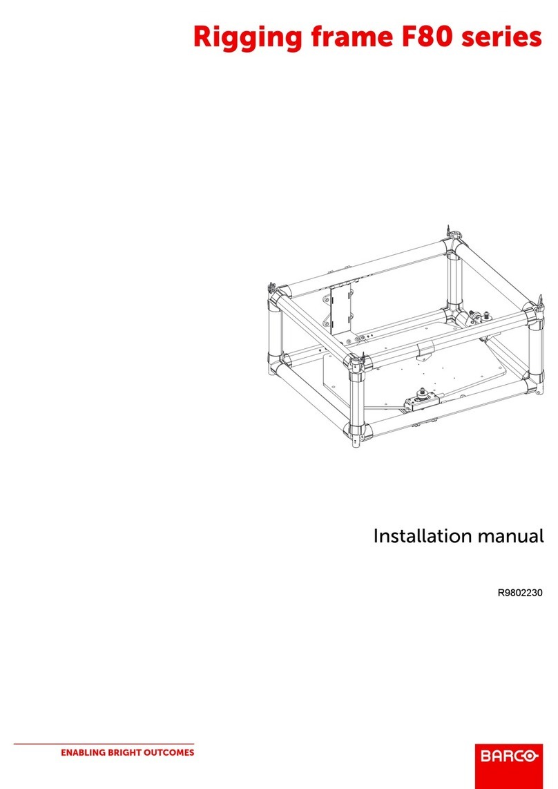
Barco Cine VERSUM 80 User manual

BARCOPROJECTIONSYSTEMS
R9841750
03062003
INSTALLATION MANUAL
Ceiling Mount for Cine Versum Projectors
Art.No.:R5976501Rev:01
Ceiling Mount Kit
Cine Versum 80

Due to constant research, the information in this manual is subject to change without notice.
Produced by BARCO NV, Oct. 2002.
All rights reserved.
Trademarks are the rights of their respective owners.
BARCOn.v./ProjectionSystems
Noordlaan5
B-8520Kuurne
Belgium
Tel:+32/56/368211
Fax:+32/56/351651
E-mail: [email protected]
Visite Barco at the web : http://www.barco.com
Printed in Belgium

BARCO———————————————————3—————————————Projection Systems
SafetyGuidelines
Caution This frame is designed for use onlywith
the Barco Cine Versum series projectors.
Use with other appliances mayresult in
instabilitycausing possible injury.
The ceiling mount supports max.25kg(55LB)
Warning The ceiling should be capable of supporting
aweight of at least 125 kg (275LB) if it
cannot, the ceiling must be reinforced.
Improper installation mayresult in serious
personal injury

BARCO———————————————————4—————————————Projection Systems
Description and Contents of the kit
Purpose of the
Kit The kit is designed for the Cine Versumseries projectors and allowsthe projector to be
mounted to the ceiling.
Illustration of the
ceiling mount
Contentsof the
Kit Followingitemsare included.
-Kit R9841750: ceiling mount
-Hexagonalnut spannerof8mm
-Installationmanual:R5976501
-Set ofspacer,bearingand fastner
-Safety Chain set
R822922
R822923
Remark The ceiling mount can also be mounted usingone ofthe 2available bars (height adjust-
ment):
R9841260:shortbarR822922
minlength =400mm(15.75inch)
max length =765 mm(30.10 inch)
R9841261:long barR822923
minlength =800mm(31.50inch)
max length =1165 mm(45.85 inch)

BARCO———————————————————5—————————————Projection Systems
Mounting the Assembly
Whathastobe
done Theceilingmountkitis first disassembledintothe ceilingplateandprojector base plateas
shown.
NecessaryTools Hexagonalkey(n°4),flatscrewdriver
Centering the
ceiling mount
1 1Markthe position on the ceiling, knowing the center ofthe
lens (which doesn’t coincide with the center ofthe ceiling
mount,seedrawing) below.
Step Action Image
Before fixing the base plate, the ceiling mount (thus the projector) has to be centered
according to the screen. Since the center ofthe lens does not coincide with the center of
theprojector.
Dimension ofceiling holes with respect to lens ofCV80

BARCO———————————————————6—————————————Projection Systems
(REF)
125
30
8
8
88
248,7
74
Illustrations
Thisplateis to be
fixedtotheceiling
with appropriate M8
bolts(notdelivered)
This isattachedto the
projector with 4no. M5
boltsgiven.
Separate theCieling mount from the packaging andopen the
topand bottompart by openingthe4screws as shown
Open these
four screws
These four holes are to be
used when height adjust-
ment bar is used.
These four slots are for
fixingto the ceiling,use
appropriatebolts (M8)
Mounting the Assembly
Dimension ofceiling holes with respect to lens ofCV80 with ceiling mount IQ BAR R9841260 and R9841261
Dim168 with short IQ bar
R9821260willbe
min400+168=568mm
max.765+168=933 mm
Dim168 with short IQ bar
R9821261willbe
min800+168=968mm
max.1165+168=1333mm

BARCO———————————————————7—————————————Projection Systems
Mountingthebase
plate to the
projector
Fix the ceiling plate to the ceiling, and assemble the base plate to the projector as shown.
1
2
1
2
Fix the spacer and bearing on the underside ofthe projector
as shown.
While fixing the base plate to the projector takecare that the
lead nut shaftpasses through the bearing while assembling.
Ifnecessaryshiftthelead nutbyrotating theleadshaftscrew
with the nut spanner.
Step Action Image
Illustrations
Mounting the Assembly
Screwsshaft
Thisshaftshouldpass
through the bearing
Bearing
B358953
Spacer
R822216
Location offixing the
spacersandbearing.

BARCO———————————————————8—————————————Projection Systems
Mounting the
assembly The assembled projector is then lifted and hocked to the ceiling plate as shown.
1
2
3
4
5
Step Action Image
Illustrations
Mounting the Assembly
Fix this plate tothe ceiling and put on thetwo screws shown
Lift theprojector with theattachment
andhangit totheplateon theceilingplate
on to thetwo screws alreadythere.
Oncehangedfixtheother twoscrews
andpositiontheprojector.
Fix the ceiling plate to the ceiling at the pre-determined
position.
Fix the base plate to the projector with 4M5 bolts given.
Fix the two screwsto the ceiling mount as shown.
Lifttheassembledprojectorandhangitonthescrewofthe
ceilingmount.
Rotate and liftthe projector and fix the rest twoscrews.
Tightenthe screwsasrequired.

BARCO———————————————————9—————————————Projection Systems
Adjustments
What has to be
done Ifnecessarythe assemblycan be adjusted (positionned)
following adjustment are possible:
-horizontal shift
-tilt in 2 planes (length axis and width axis)
NecessaryTools Allan (hexagonal) key(n04), nut spanner 8mm.
Adjustment
Illustrations
Toperformadjustment ofthe assemblyfollowthe next procedure:
Adjust the projector alignmentsuntil the desired image is obtained. Tighten all the bolts
after the desired image is achieved.
This adjustment in this direction
can be done with these slot
Thisadjustmentinthisdirection
canbedonebyrotatingtheshaftscrew
withanutspannerof8mm
Thisadjustmentinthisdirection
canbedonebythisslot.

BARCO———————————————————10—————————————Projection Systems
SafetyChain The safetychain can be attached to the projector in the location as shown
1
2
3
1
1
The safetychain provided should be attached to the
projector as shownin fig.
Fix the other end ofthe safetychain on a firmplace on the
ceiling in a similar manner.
Use the M8 nuts, bolts and washers to lockthe chain.
Step Action Image
Illustrations
Fixing safetychain
M8 nut, bolt and washer
used to lockthe chain.
i)Check the stabilityof the ceiling mount.
ii)The installation is complete after aproper image at the desired place is
achieved.
Other manuals for Cine VERSUM 80
2
This manual suits for next models
1
Other Barco Rack & Stand manuals