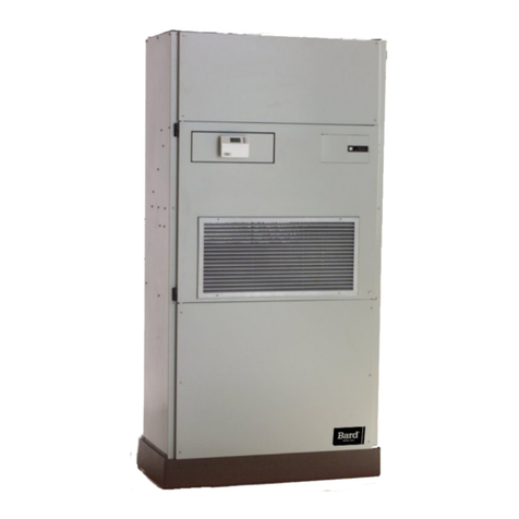
Bard W24HY-A User manual

Page 1 of 49
Wall Mounted Package
Heat Pump
Models:
INSTALLATION INSTRUCTIONS
W18HY-A
Bard Manufacturing Company, Inc.
Bryan, Ohio 43506
www.bardhvac.com
Manual: 2100-790
Supersedes: NEW
Date: 6-29-23
W24HY-A
W24HY-B
W24HY-C
W24HYDA
W24HYDB
W24HYDC
W30HY-A
W30HY-B
W30HY-C
W30HYDA
W30HYDB
W30HYDC
W36HY-A
W36HY-B
W36HY-C
W36HYDA
W36HYDB
W36HYDC

Manual 2100-790
Page 2 of 49
CONTENTS
Safety Instructions .................................................4
General Information .............................................10
Heat Pump Wall Mount Model Nomenclature ........ 10
Shipping Damage ............................................... 10
General ............................................................. 10
Duct Work ......................................................... 10
Filters ............................................................... 11
Fresh Air Intake ................................................. 11
Installation.............................................................13
Basic Installation Design and Application Planning 13
Wall Construction ........................................... 13
Outdoor Area Inspection.................................. 13
Condensate Water Drainage ............................. 13
Indoor Ducted and Non-Ducted Applications......... 13
Indoor Supply Airow...................................... 13
Indoor Return Airow...................................... 14
Ducted Applications ....................................... 14
Free Blow Applications.................................... 14
Thermostat or Indoor Temperature Sensor
Placement ..................................................... 14
Unit Installation ................................................. 15
Materials/Tool List .......................................... 15
Wall Preparation............................................. 15
Wall Mount Installation to Wall Surface ............ 15
Wiring – Main Power........................................... 22
Wiring – Low Voltage........................................... 22
Low Voltage Connections ................................. 22
Unit Shutdown Feature ................................... 22
Balanced ClimateTM Feature............................. 22
Dehumidication Feature ................................ 23
Ventilation Features ........................................ 23
Low Ambient Control (LAC) ............................. 23
Outdoor Temperature Switch and Freeze
Protection Thermostat ................................. 23
Alarm Relay Feature ....................................... 23
Dirty Filter Switch Indicator (DFS).................... 23
Start Up ...................................................................27
General ......................................................... 27
Topping Off System Charge................................. 27
Safety Practices ................................................ 27
Important Installer Note ..................................... 27
High and Low Pressure Switch............................ 28
Three Phase Scroll Compressor Start Up
Information....................................................... 28
Phase Monitor ................................................... 28
Condenser Fan Operation ................................... 28
Sequence of Operation....................................... 28
Cooling ......................................................... 28
Heating ......................................................... 28
Dehumidication and Electronic Expansion
Valve (EEV) .................................................... 28
Balanced Climate Mode .................................. 28
Defrost Cycle..................................................... 29
Low Pressure Switch Bypass Operation ............. 29
High Pressure Switch Operation....................... 30
Vent Connection Plug.......................................... 30
Pressure Service Ports ........................................ 30
Service Hints ..................................................... 30
Service .....................................................................32
Solid State Heat Pump Control Troubleshooting
Procedure ......................................................... 32
Checking Temperature Sensor Outside
Unit Circuit........................................................ 33
Troubleshooting Nidec SelecTech Series ECM
Motors............................................................... 34
If the Motor Is Running................................... 34
If the Motor Is Not Running............................. 34
Model SelecTech Communication Diagnostics ... 35
Fan Blade Setting Dimensions ............................. 36
Removal of Fan Shroud....................................... 36
R-410A Refrigerant Charge ................................. 36
Setting Unit Airow ............................................ 40
Blower Speeds ............................................... 40
Speed Tap 1 – Vent/Blower Only .................. 41
Speed Tap 2 – Balanced Climate ................. 41
Speed Tap 3 – Default LO Cooling &
Heating ............................... 41
Speed Tap 4 – Optional MED Cooling &
Heating ............................... 41
Speed Tap 5 – Optional HI Cooling &
Heating ............................... 41
Dirty Filter Switch ............................................. 42
Dirty Filter Switch Adjustment ......................... 42

Manual 2100-790
Page 3 of 49
FIGURES
Figure 1 Fresh Air Damper ................................ 12
Figure 2 Unit Dimensions ................................. 16
Figure 3A Mounting Instructions – W18H, W24H.. 17
Figure 3B Mounting Instructions – W30H, W36H.. 18
Figure 4 Electric Heat Clearance – All Models...... 19
Figure 5 Wall Mounting Instructions .................. 20
Figure 6 Wall Mounting Instructions .................. 20
Figure 7 Common Wall Mounting Installations .... 21
Figure 8 Thermostat Connections ...................... 25
Figure 9 Thermostat Connections ...................... 26
Figure 10 Defrost Control Board .......................... 31
Figure 11 Motor Connections .............................. 34
Figure 12 Motor Connections .............................. 35
Figure 13 Fan Blade Setting ............................... 36
Figure 14 Speed Taps......................................... 40
Figure 15 Speed Taps......................................... 40
Figure 16 Dirty Filter Switch Location.................. 42
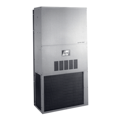
Figure 17 Adjusting Dirty Filter Switch................. 43
GRAPHS
Graph 1 W18HY FAD-NE2, 3 W/O Exhaust
Ventilation Delivery ............................. 48
Graph 2 W24HY FAD-NE2, 3 W/O Exhaust
Ventilation Delivery ............................. 48
Graph 3 W30HY FAD-NE2, 3 W/O Exhaust
Ventilation Delivery ............................. 49
Graph 4 W36HY FAD-NE2, 3 W/O Exhaust
Ventilation Delivery ............................. 49
TABLES
Table 1 Clearance Required for Service Access
and Adequate Condenser Airow.......... 16
Table 2 Minimum Clearances Required to
Combustible Materials ........................ 16
Table 3 Low Voltage Connections .................... 23
Table 4 Wall Thermostats ............................... 24
Table 5 Humidity Controls .............................. 24
Table 6 CO2Controller.................................... 24
Table 7 Thermostat Wire Size.......................... 24
Table 8 Troubleshooting ................................. 32
Table 9 Temperature vs. Resistance................. 33
Table 10 Fan Blade Dimension ......................... 36
Table 11A Cooling Pressure ................................ 37
Table 11B Heating Pressure................................ 37
Table 12 Cooling Pressure – Balanced Climate
Airow .............................................. 38
Table 13 Electrical Specications ..................... 39
Table 14 Recommended Airow........................ 40
Table 15 Blower Speeds for Unit Operational
Modes............................................... 41
Table 16 Indoor Blower Performance ................. 44
Table 17 Maximum ESP of Operation –
Electric Heat Only ............................. 45
Table 18 Electric Heat ..................................... 45
Table 19 Optional Accessories .......................... 46
Table 20 Vent and Control Options .................... 47
NOTICE
APPLIANCEACCESSIBLE TO THE GENERAL
PUBLIC.

Manual 2100-790
Page 4 of 49
SAFETY INSTRUCTIONS
Fire hazard.
Maintain minimum 1/4" clearance between the
supply air duct and combustible materials in
the rst 3' feet of ducting.
Failure to do so could result in re causing
damage, injury or death.
!WARNING
Heavy item hazard.
Use more than one person to handle unit.
Failure to do so could result in unit damage or
serious injury.
!WARNING
Electrical shock hazard.
Do not operate this equipment without an
earth ground attached and always disconnect
the remote electric power supplies before
servicing.
Electrical shock can result in serious injury or
death.
!WARNING
READ ALL INSTRUCTIONS BEFORE USE
Your safety and the safety of others are very important.
We have provided many important safety messages in this manual and on your appliance. Always read and follow all
safety messages.
ANSI Z535.5 Denitions:
DANGER: Indicate[s] a hazardous situation which, if not avoided, will result in death or serious injury. The signal
word “DANGER” is to be limited to the most extreme situations. DANGER [signs] should not be used for property
damage hazards unless personal injury risk appropriate to these levels is also involved.
WARNING: Indicate[s] a hazardous situation which, if not avoided, could result in death or serious injury. WARNING
[signs] should not be used for property damage hazards unless personal injury risk appropriate to this level is also
involved.
CAUTION: Indicate[s] a hazardous situation which, if not avoided, could result in minor or moderate injury. CAUTION
[signs] without a safety alert symbol may be used to alert against unsafe practices that can result in property damage
only.
NOTICE: [this header is] preferred to address practices not related to personal injury. The safety alert symbol shall
not be used with this signal word. As an alternative to “NOTICE” the word “CAUTION” without the safety alert
symbol may be used to indicate a message not related to personal injury.
NOTICE
APPLIANCEACCESSIBLE TO THE GENERAL
PUBLIC.

Manual 2100-790
Page 5 of 49
Electrical shock hazard.
Have a properly trained individual perform
these tasks.
Failure to do so could result in electric shock
or death.
!WARNING
Sharp metallic edges.
Take care and wear appropriate protective
devices to avoid accidental contact with sharp
edges.
Failure to do so can result in personal injury.
CAUTION
!
The following symbols are displayed on units.
This symbol indicates that the Operation Manual should be read carefully.
This symbol indicates that a service personnel should be handling this equipment with reference to
the Installation Manual.
This symbol indicates that information is available such as the Operation Manual or Installation
Manual.

Manual 2100-790
Page 6 of 49
IMPORTANT SAFETY INSTRUCTIONS
!WARNING
To reduce the risk of explosion, re, death, electric shock, scalding or injury to persons
when using this product, follow basic precautions, including the following:
GENERAL
·The equipment covered in this manual is to be installed by trained, experienced service and installation
technicians.
· This appliance is not intended for use by persons (including children) with reduced physical, sensory
or mental capabilities, or lack of experience and knowledge, unless they have been given supervision or
instruction concerning use of the appliance by a person responsible for their safety.
· The refrigerant system is completely assembled and charged. All internal wiring is complete.
· The unit is designed for use with or without duct work. Flanges are provided for attaching the supply and
return ducts.
· These instructions explain the recommended method to install the air-cooled self-contained unit and the
electrical wiring connections to the unit.
· These instructions and any instructions packaged with any separate equipment required to make up the
entire air conditioning system should be carefully read before beginning the installation. Note particularly
“Starting Procedure” and any tags and/or labels attached to the equipment.
· While these instructions are intended as a general recommended guide, they do not supersede any national
and/or local codes in any way. Authorities having jurisdiction should be consulted before the installation is
made. See Additional Publications for information on codes and standards.
· Size of unit for a proposed installation should be based on heat loss calculation made according to
methods of Air Conditioning Contractors of America (ACCA). The air duct should be installed in accordance
with the Standards of the National Fire Protection Association for the Installation of Air Conditioning and
Ventilating Systems of Other Than Residence Type, NFPA No. 90A, and Residence Type Warm Air Heating
and Air Conditioning Systems, NFPA No. 90B. Where local regulations are at a variance with instructions,
installer should adhere to local codes.
INSTALLATION
· This product is not intended for use at altitudes exceeding 2,000 meters (6,561 feet). For appliances
intended for use at altitudes exceeding 2 000 m (6,561 feet), the maximum altitude of use shall be stated.
· Before use, the appliance must be properly installed as described in this manual.
· Contact the authorized service technician for repair or maintenance of this unit.
· Contact the installer for installation of this unit.
· The air conditioner is not intended for use by young children or invalids without supervision.
· Young children should be supervised to ensure that they do not play with the air conditioner.
· Installation work must be performed in accordance with the National Electric Code by qualied and
authorized personnel only.
· Connect to a properly rated, protected, and sized power circuit to avoid electrical overload.
· Adhere to all industry recommended safety procedures including the use of long-sleeved gloves and safety
glasses.
· Use care when unpacking and installing. The edges of the product may be sharp.
· Keep packaging materials out of the reach of children. These materials can pose a suffocation risk to
children.
OPERATION
· This appliance is not intended for use by persons (including children) with reduced physical, sensory,
or mental capabilities, or lack of experience and knowledge, unless they have been given supervision or
instruction concerning use of the appliance by a person responsible for their safety.
· Use this appliance only for its intended purpose.
· Never attempt to operate this appliance if it is damaged, malfunctioning, partially disassembled, or has
missing or broken parts.
· Do not tamper with controls.

Manual 2100-790
Page 7 of 49
INSTRUCTIONS DE SÉCURITÉ
LIRE TOUTES LES INSTRUCTIONS AVANT UTILISATION
Votre sécurité et celle des autres sont très importantes.
Nous avons fourni de nombreux messages de sécurité importants dans ce manuel et sur votre appareil. Lisez et
suivez toujours tous les messages de sécurité.
Dénitions ANSI Z535.5:
DANGER: Indique une situation dangereuse qui, si elle n’est pas évitée, entraînera certainement la mort ou des blessures
graves. Le mot « DANGER » doit être limité aux situations extrêmes. Les indications «DANGER» ne doivent pas être
utilisées pour les risques de dégâts matériels, à moins qu’il n’existe un risque concomitant de blessures corporelles.
AVERTISSEMENT: Indique une situation dangereuse qui, si elle n’est pas évitée, peut entraîner la mort ou des blessures
graves. Les indications «AVERTISSEMENT» ne doivent pas être utilisées pour les risques de dégâts matériels, à moins
qu’il n’existe un risque concomitant de blessures corporelles.
ATTENTION: Indique une situation dangereuse qui, si elle n’est pas évitée, peut entraîner des blessures mineures à
modérées. Les indications «ATTENTION», sans symbole d’avertissement, peuvent être utilisées pour alerter sur des
pratiques dangereuses pouvant entraîner des dégâts matériels uniquement.
REMARQUE: cet avis concerne les pratiques n’entraînant aucune blessure corporelle. Le symbole d’avertissement ne doit
pas être utilisé avec ce mot. Comme alternative à « AVIS », le mot « ATTENTION » sans symbole d’avertissement peut être
utilisé pour indiquer un message non lié à des blessures corporelles.
APPAREIL ACCESSIBLE AU GRAND PUBLIC.
£
AVERTISSEMENT
A
ATTENTION
REMARQUE
WARNING
£
AVERTISSEMENT
A
ATTENTION
REMARQUE
WARNING
£
AVERTISSEMENT
A
ATTENTION
REMARQUE
WARNING
Risque lié aux objets lourds.
Plusieurs personnes sont nécessaires à la
manipulation de l’unité.
Le non-respect de cette consigne peut entraîner
dégâts à l’unité ou des blessures graves.
!AVERTISSEMENT
Risque d’incendie.
Conserver un dégagement minimal de
6,35 mm/1/4 po entre le conduit d’air soué
et les matériaux combustibles sur les
900 premiers millimètres (3 pi) du conduit.
Le non-respect de cette consigne entraîne
des risques de dégâts matériels, de blessures
corporelles ou de décès.
!AVERTISSEMENT
Risque de choc électrique.
Ne pas faire fonctionner cet équipement sans
qu’il soit relié à la terre et toujours débrancher
les alimentations électriques avant de procéder
aux opérations d’entretien.
Une électrisation peut entraîner des blessures
graves ou la mort.
!AVERTISSEMENT
REMARQUE

Manual 2100-790
Page 8 of 49
Les symboles suivants sont afchés sur les unités.
Ce symbole indique que le manuel d’utilisation doit être lu attentivement.
Ce symbole indique qu’un membre du personnel de service devrait manipuler cet équipement en se
référant au manuel d’installation.
Ce symbole indique que des informations sont disponibles telles que le manuel d’utilisation ou le
manuel d’installation.
Risque de choc électrique.
Ces tâches doivent être réalisées par une
personne parfaitement qualiée et formée.
Le non-respect de cette consigne peut entraîner
des chocs électriques ou la mort.
!AVERTISSEMENT
Arêtes métalliques vives.
Faites attention et portez des dispositifs de
protection appropriés pour éviter tout contact
accidentel avec des arêtes vives.
Le non-respect de cette consigne peut entraîner
des blessures corporelles.
!ATTENTION

Manual 2100-790
Page 9 of 49
INSTRUCTIONS DE SÉCURITÉ IMPORTANTES
!AVERTISSEMENT
Pour réduire le risque d’explosion, d’incendie, de décès, de choc électrique, d’échaudure ou de
blessures pour les personnes lors de l’utilisation de ce produit, suivez les précautions de base,
notamment les suivantes :
GÉNÉRALITÉS
· L’équipement couvert dans ce manuel doit être installé par des techniciens de service et d’installation formés et
expérimentés.
· Cet appareil n’est pas destiné à être utilisé par des personnes (y compris des enfants) ayant des capacités physiques,
sensorielles ou mentales réduites, ou un manque d’expérience et de connaissances, à moins qu’elles n’aient reçu la
supervision ou l’instruction concernant l’utilisation de l’appareil par une personne responsable de leur sécurité.
· Le système de réfrigérant est complètement assemblé et chargé. Tout le câblage interne est complet.
· L’unité est conçue pour être utilisée avec ou sans conduits. Des brides sont prévues pour xer les conduits
d’alimentation et de retour.
· Ces instructions expliquent la méthode recommandée pour installer l’unité autonome refroidie à l’air et les
connexions de câblage électrique à l’unité.
· Ces instructions et toutes les instructions emballées avec tout équipement distinct requis pour constituer l’ensemble
du système de climatisation doivent être lues attentivement avant de commencer l’installation. Notez en particulier «
Procédure de démarrage » et les étiquettes et / ou étiquettes attachées à l’équipement.
· Bien que ces instructions soient conçues comme un guide général recommandé, elles ne remplacent en aucune
façon les codes nationaux et/ou locaux. Les autorités compétentes devraient être consultées avant que l’installation
ne soit effectuée. Voir d’autres publications pour obtenir des renseignements sur les codes et les normes.
· La taille de l’unité pour une installation proposée devrait être basée sur le calcul de la perte de chaleur effectué
selon les méthodes de Air Conditioning Contractors of America (ACCA). Le conduit d’air devrait être installé
conformément aux Normes de la National Fire Protection Association for the Installation of Air Conditioning and
Ventilating Systems of Other Than Residence Type, NFPA No. 90A, et aux Systèmes de chauffage et de climatisation
d’air chaud de type résidence, NFPA No. 90B. Lorsque les réglementations locales sont en contradiction avec les
instructions, l’installateur doit respecter les codes locaux.
L'INSTALLATION
· Ce produit n’est pas destiné à être utilisé à des altitudes supérieures à 2 000 mètres (6 561 pieds). Pour les
appareils destinés à être utilisés à des altitudes supérieures à 2 000 m (6 561 pieds), l’altitude maximale
d’utilisation doit être indiquée.
· Avant utilisation, l’appliance doit être correctement installée comme décrit dans ce manuel.
· Communiquez avec le technicien d’entretien autorisé pour la réparation ou l’entretien de cette unité.
· Contactez le programme d’installation pour l’installation de cet appareil.
· Le climatiseur n’est pas destiné à être utilisé par de jeunes enfants ou des invalides sans surveillance.
· Les jeunes enfants devraient être surveillés pour s’assurer qu’ils ne jouent pas avec le climatiseur.
· Les travaux d’installation doivent être effectués conformément au Code national de l’électricité par du personnel
qualié et autorisé uniquement.
· Connectez-vous à un circuit d’alimentation correctement évalué, protégé et dimensionné pour éviter les
surcharges électriques.
· Respectez toutes les procédures de sécurité recommandées par l’industrie, y compris l’utilisation de gants à
manches longues et de lunettes de sécurité.
· Faites attention lors du déballage et de l’installation. Les bords du produit peuvent être tranchants.
· Gardez les matériaux d’emballage hors de la portée des enfants. Ces matériaux peuvent poser un risque
d’étouffement pour les enfants.
OPÉRATION
· Cet appareil n’est pas destiné à être utilisé par des personnes (y compris des enfants) ayant des capacités
physiques, sensorielles ou mentales réduites, ou un manque d’expérience et de connaissances, à moins
qu’elles n’aient reçu une supervision ou une instruction concernant l’utilisation de l’appareil par une personne
responsable de leur sécurité.
· Utilisez cet appareil uniquement aux ns prévues.
· N’essayez jamais de faire fonctionner cet appareil s’il est endommagé, défectueux, partiellement démonté ou s’il
a des pièces manquantes ou cassées.
· Ne pas altérer les contrôles.

Manual 2100-790
Page 10 of 49
GENERAL INFORMATION
General
The equipment covered in this manual is to be installed
by trained, experienced service and installation
technicians.
The refrigerant system is completely assembled and
charged. All internal wiring is complete.
The unit is designed for use with or without duct work.
Flanges are provided for attaching the supply and
return ducts.
These instructions explain the recommended method
to install the air cooled self-contained unit and the
electrical wiring connections to the unit.
These instructions and any instructions packaged with
any separate equipment required to make up the entire
air conditioning system should be carefully read before
beginning the installation. Note particularly “Starting
Procedure” and any tags and/or labels attached to the
equipment.
While these instructions are intended as a general
recommended guide, they do not supersede any
national and/or local codes in any way. Authorities
having jurisdiction should be consulted before the
installation is made. See Additional Publications
for information on codes and standards.
Size of unit for a proposed installation should be
based on heat loss/gain calculation made according
to methods of Air Conditioning Contractors of America
(ACCA). The air duct should be installed in accordance
with the Standards of the National Fire Protection
Association for the Installation of Air Conditioning and
Ventilating Systems of Other Than Residence Type,
NFPA No. 90A, and Residence Type Warm Air Heating
and Air Conditioning Systems, NFPA No. 90B. Where
local regulations are at a variance with instructions,
installer should adhere to local codes.
Shipping Damage
Upon receipt of equipment, the carton should be
checked for external signs of shipping damage. If
damage is found, the receiving party must contact
the last carrier immediately, preferably in writing,
requesting inspection by the carrier’s agent.
Additional Publications
These publications can help when installing the heat
pump. They can usually be found at the local library
or purchased directly from the publisher. Be sure to
consult the current edition of each standard.
National Electrical Code ......................ANSI/NFPA 70
Standard for the Installation of Air Conditioning and
Ventilating Systems
.......................................................ANSI/NFPA 90A
Standard for Warm Air Heating and Air Conditioning
Systems
.......................................................ANSI/NFPA 90B
Load Calculation for Winter and Summer Air
Conditioning
....................................... ACCA Manual J Residential
Duct Design for Residential Winter and Summer Air
Conditioning and Equipment Selection
....................................................... ACCA Manual D
For more information, contact these publishers:
ACCA Air Conditioning Contractors of America
1712 New Hampshire Ave. N.W.
Washington, DC 20009
Telephone: (202) 483-9370
Fax: (202) 234-4721
ANSI American National Standards Institute
11 West Street, 13th Floor
New York, NY 10036
Telephone: (212) 642-4900
Fax: (212) 302-1286
ASHRAE American Society of Heating, Refrigeration
and Air Conditioning Engineers, Inc.
1791 Tullie Circle, N.E.
Atlanta, GA 30329-2305
Telephone: (404) 636-8400
Fax: (404) 321-5478
NFPA National Fire Protection Association
Batterymarch Park
P.O. Box 9101
Quincy, MA 02269-9901
Telephone: (800) 344-3555
Fax: (617) 984-7057

Manual 2100-790
Page 11 of 49
Heat Pump Wall Mount Model Nomenclature
CONTROL
X – None (Standard)
E – Low Ambient Control
F – Filter Replacement Pressure
Switch, Alarm Relay & Low
Ambient Control
J – Alarm Relay & Low Ambient
Control
K – Start Kit & Low Ambient
Control
M –Start Kit, Low Ambient
Control & Alarm Relay
V – DDC Controls
W 36 H Y –A 0Z X X X X X X
MODEL SERIES
H – Heat Pump
CAPACITY
18 – 1½ Ton
24 – 2 Ton
30 – 2½ Ton
36 – 3 Ton
COIL OPTIONS
X – Standard
1 – Phenolic Coated Evaporator
2 – Phenolic Coated Condenser
3 – Phenolic Coated Evaporator and
Condenser
4 – 3rd Party Unit Coating: Condenser
5 – 3rd Party Unit Coating: Entire Unit
PLACEHOLDER
X – Future Use
COLOR OPTIONS
X – Beige
1 – White
4 – Gray
5 – Desert Brown
8 – Dark Bronze
A – Aluminum
S – Stainless Steel
FILTER
X – 1" Throwaway (Standard)
W – 1" Washable
P – 2" MERV 8
M – 2" MERV 11
N – 2" MERV 13
SPECIAL CONFIGURATION
(–) – Standard System
D – Dehumidication
REVISION
ELECTRICAL
A – 230/208/60/1
B – 230/208/60/3
C – 460/60/3
ELECTRIC HEAT
00 – No Electric Heat, No Circuit Breaker
0Z – No Electric Heat, w/Circuit Breaker
04 – 4KW Electric Heat
05 – 5KW Electric Heat
06 – 6KW Electric Heat
08 – 8KW Electric Heat
09 – 9KW Electric Heat
10 – 10KW Electric Heat
12 – 12KW Electric Heat
15 – 15KW Electric Heat
VENT
X – Fresh Air Damper, No Exhaust
A – Fresh Air Damper, w/Exhaust
B – Blank-Off Plate
D – DDC/BrightStat, 0-10V Economizer
M – Commercial Room Ventilator, ON/OFF Operation Only
R – Energy Recovery Ventilator
S – Partial Flow Economizer w/JADE
V – Commercial Ventilator, Modulating Operation w/Board
Y – Full Flow Economizer w/JADE, Dry Bulb
Z – Economizer, DB & WB, Full Flow

Manual 2100-790
Page 12 of 49
Duct Work
All duct work, supply and return, must be properly
sized for the design airow requirement of the
equipment. Air Conditioning Contractors of America
(ACCA) is an excellent guide to proper sizing. All duct
work or portions thereof not in the conditioned space
should be properly insulated in order to both conserve
energy and prevent condensation or moisture damage.
Refer to the Maximum ESP of Operation table on page
45.
Design the duct work according to methods given by
the Air Conditioning Contractors of America (ACCA).
When duct runs through unheated spaces, it should
be insulated with a minimum of 1" of insulation. Use
insulation with a vapor barrier on the outside of the
insulation. Flexible joints should be used to connect
the duct work to the equipment in order to keep the
noise transmission to a minimum.
For all models, a 1/4" clearance to combustible
material for the rst 3' of duct attached to the outlet
air frame is required. See Ducted Applications on page
14 and Figures 3A and 3B (pages 17 and 18) and
Figure 4 (page 19) for further details.
Ducts through the walls must be insulated and all joints
taped or sealed to prevent air or moisture entering the
wall cavity.
Some installations may not require any return air duct.
A metallic return air grille is required with installations
not requiring a return air duct. The spacing between
louvers on the grille shall not be larger than 5/8".
Any grille that meets with 5/8" louver criteria may be
used. It is recommended that Bard Return Air Grille
Kit RG-2W through RG-3W or RFG-2W through RFG-
3W be installed when no return duct is used. Contact
distributor or factory for ordering information. If using a
return air lter grille, lters must be of sufcient size to
allow a maximum velocity of 400 fpm.
NOTE: If no return air duct is used, applicable
installation codes may limit this cabinet to
installation only in a single story structure.
Filters
A 1" throwaway lter is standard with each unit. The
lter slides into position making it easy to service. This
lter can be serviced from the outside by removing the
lter access panel. A 1" washable lter and 2" pleated
lter are also available as optional accessories. The
internal lter brackets are adjustable to accommodate
the 2" lter by bending two tabs down on each side of
the lter support bracket.
Fresh Air Intake
All units are built with fresh air inlet slots punched in
the service door.
If the unit is equipped with a fresh air damper
assembly, the assembly is shipped already attached
to the unit. The damper blade is locked in the closed
position. To allow the damper to operate, the maximum
and minimum blade position stops must be installed
(see Figure 1).
Graphs found on pages 48 and 49 give approximate
fresh air amounts based on the blade position stop
location.
All capacity, efciency and cost of operation
information is based upon the fresh air blank-off plate
in place and is recommended for maximum energy
efciency.
The blank-off plate is available upon request from the
factory and is installed in place of the fresh air damper
shipped with each unit.
FIGURE 1
Fresh Air Damper
MIS-938
BLADE IS LOCKED CLOSED
FOR SHIPPING

Manual 2100-790
Page 13 of 49
INSTALLATION
Basic Installation Design and
Application Planning
Successful unit installations require proper planning
and site inspection before installation begins. Before
installing the wall mount unit, make sure that all
service and airow clearances are met and that the
unit can meet all applicable code and regulation
requirements. Provide an inspection of both the inside
and outside of the structure by reviewing oorplans
and/or visiting the installation site.
Wall Construction
The wall must be inspected to ensure that the weight
of the unit can be supported. Be sure to review all
applicable construction codes and regulations including
seismic requirements. When inspecting wood frame
walls, the wall construction must be strong and
rigid enough to carry the weight of the unit without
transmitting any unit vibration. It is important that
the side unit wall mounting lags and optional bottom
bracket are supported by structural members inside
the wall cavity. Concrete block and brick walls must be
thoroughly inspected to ensure that they are capable of
carrying the weight of the installed unit. Metal buildings
must contain structural components to support the unit
weight. If heavily corrugated siding is present, it may
need to be trimmed and ashed similar to a window
to provide a at, even surface to attach and seal the
unit to the wall. Heavy gauge corrugations that would
be present on shipping containers and blast-proof
structures may require the installation of a metal plate
over the corrugated area. It is important that the unit
area is weatherized and sealed to avoid air and water
inltration into the area between the unit and the wall.
Outdoor Area Inspection
Inspect the outdoor area of the jobsite or review
construction plans and locate the area where the wall
mount is to be installed. The outdoor area must be
free from obstructions including fences, bushes and
walls that will hinder unit operation regarding outdoor
condenser airow and unit serviceability. Do not
install units in enclosed areas that limit the amount
of ambient temperature airow. Warm air will exit
the front condenser section of the unit, and outdoor
ambient temperature air must be able to enter side
intake condenser openings of the unit. Portable or
modular building placement must be in a way that the
wall mount units have a constant supply of outdoor air
for proper unit operation. Make sure that the service
panels of the unit are accessible. Inspect wall surfaces
for obstructions that could hinder unit installation and
servicing including outdoor electrical conduits, junction
boxes, wall drains, vent hoods, windows, doors,
overhangs and posts.
NOTE: Before mounting the heat pump unit,
consideration should be given to the
condensate removal from the outdoor coil
when in heating mode. The unit must be
mounted high enough above grade to ensure
that ice will not build up under the unit and
come into contact with the base of the unit.
If allowed, this could cause damage to the
coil and other base components. Also, be sure
there are no air obstructions to the sides or
front of the unit, such as bushes or fences,
that would inhibit condenser airflow.
Condensate Water Drainage
Review all codes and requirements for unit condensate
drainage. A clear, exible PVC drain hose (3/4" ID, 1"
OD) extends from the drain pan in the upper section of
the unit and extends down to the unit base. An opening
is supplied towards the back of the unit base for the
drain hose to pass through, and the hose extends 1"
to 2" below the unit base. Water removed from the
indoor air (condensate) will be expelled from the unit
in large amounts during cooling operation through the
hose. Units running in cooling operation in cold outdoor
below freezing conditions can cause the condensate
to freeze after leaving the drain hose. In the event the
drain hose is connected to a drain system of some type,
it must be an open or vented type system to ensure
proper drainage throughout seasonal use.
Indoor Ducted and Non-Ducted
Applications
Air distribution inside the structure being conditioned
plays an important role in making sure the area is
a consistent temperature. Improper air distribution
can result in areas being cooler or warmer, electrical
equipment not receiving sufcient airow or occupancy
discomfort felt inside an area. Thermostat or indoor
temperature sensor placement inside the area being
conditioned also plays an important role in indoor
climate control.
Indoor Supply Airow
Indoor installation areas must provide a non-restrictive
path for the conditioned supply air to leave supply grilles
and registers. Inspect the area to ensure that all indoor
portions of the room or rooms will have access to supply
air. Ductwork may be used to ensure proper air circulation
and all provided ductwork guidelines and clearances must
be followed. Non-ducted applications must use a supply
louver grille installed over the supply opening inside the
room. Be sure to adjust supply deectors to properly
disperse the conditioned supply air to all parts of the
room. Avoid closing sections of the supply grilles which
would cause unneeded supply duct pressurization.

Manual 2100-790
Page 14 of 49
Fire hazard.
Maintain minimum 1/4" clearance between the
supply air duct and combustible materials in
the rst 3' of ducting.
Failure to do so could result in re causing
damage, injury or death.
!WARNING
Indoor Return Airow
A non-restrictive path for room air returning to the
center section of the unit must be provided inside
the room. Avoid placing objects including furniture,
electronics equipment, equipment racks and cabinets
directly in front of the unit return grilles and registers.
Bard recommends at least 2' between solid objects
and return grilles or registers. Ductwork may be used to
ensure proper air circulation and all provided ductwork
guidelines and clearances must be followed. Non-
ducted applications must use a return louver grille
installed over the return opening inside the room.
Ducted Applications
Field fabricated supply and return duct work may be
installed inside the structure being conditioned. A short
supply and/or return stub duct may be connected to the
unit supply and return anges before unit installation to
help with duct connections inside the structure. Supply
and return ducts must be properly sized for the design
airow requirement of the equipment. Air Conditioning
Contractors of America (ACCA) is an excellent guide to
proper sizing. All duct work or portions thereof not in the
conditioned space should be properly insulated in order
to conserve energy, reduce heat conductivity, and prevent
condensation or moisture damage. Refer to Maximum
External Static Pressure (ESP) of Operation Table 17 on
page 45. Design the duct work according to methods
given by the Air Conditioning Contractors of America
(ACCA). When duct work is installed in unheated spaces,
it should be insulated with a minimum of 1" of insulation.
Use insulation with a vapor barrier on the outside of the
insulation. Flexible joints should be used to connect the
duct work to the equipment in order to keep the noise
transmission to a minimum. Ducts through the walls must
be insulated and all joints taped or sealed to prevent air
or moisture from entering the wall cavity.
The unit itself is suitable for 0" clearance, but the
supply air duct ange and the rst 3' of supply air duct
require a minimum of 1/4" clearance to combustible
material for all models. However, it is generally
recommended that a 1" clearance is used for ease of
installation and maintaining the required clearance to
combustible material. See Figures 3A and 3B on pages
17 and 18 for details on opening sizes.
Free Blow Applications
Some installations may not require extensive supply
duct work throughout the structure and are referred
to as free blow applications. A short eld-fabricated
supply duct must be used in the wall cavity to
transition between the supply collar on the unit and
the supply louver grille in the room. The duct must
be properly insulated in order to conserve energy,
reduce heat conductivity and prevent condensation or
moisture damage. All joints must be taped or sealed to
prevent air or moisture entering the wall cavity. Follow
all clearances including distances to combustible
materials and all instructions provided in this manual.
A non-restrictive metallic supply air grille with
deectors is required for free blow applications. Contact
the local Bard distributor or visit www.bardhvac.com for
ordering information.
A metallic return air grille is required for non-ducted
applications. The spacing between louvers on the grille
shall not be larger than 5/8". It is recommended that a
Bard Return Air Grille Kit be installed that is designed
specically for the wall mount product. Contact the
local Bard distributor or visit www.bardhvac.com for
ordering information. A eld-supplied return grille
that meets the 5/8" louver criteria and does not cause
the unit to exceed the maximum specied external
static pressure (ESP) may be used. If using a return
air lter grille, lters must be of sufcient size to
allow a maximum velocity of 400 fpm. Filter return
air grilles do not lter air being brought into the
structure through ventilation options including fresh air
dampers, ventilators, economizers and energy recovery
ventilators. Be sure to install the return grille with the
louvers pointed downward towards the oor. This will
help ensure return air is drawn upward from the oor
and improve air circulation in the room.
NOTE: If no return air duct is used, applicable
installation codes may limit this cabinet to
installation only in a single story structure.
Thermostat or Indoor Temperature Sensor Placement
The location and installation of the thermostat or
temperature sensor that monitors indoor temperature is
very important regarding unit operation. Avoid placing
the thermostat in an area exposed to direct sunlight
or air from doorways leading outdoors. Use a piece
of insulating material to close off conduit openings
or holes in the wall surface for wire entry into the
thermostat or temperature sensor. This will help avoid
non-conditioned air from entering the thermostat
and effecting temperature and/or humidity readings.
As common practice, the thermostat or temperature
sensor should measure the temperature of the air
being returned to the unit, and not the conditioned
air being supplied by the unit. Placing the thermostat
or temperature sensor near a return air opening will
normally result in optimal unit performance.

Manual 2100-790
Page 15 of 49
Unit Installation
Make sure to have the proper tools at the work site that
are needed for unit installation. The following steps
are provided to ensure the unit is installed properly to
the wall surface, and that the unit will provide years of
service with minimal service requirements.
Materials/Tools List
Additional hardware and miscellaneous supplies are
needed for installation. These items are eld supplied
and must be sourced before installation. This list also
includes tools needed for installation.
• Appropriate safety gear including gloves and safety
glasses
• 5/16" hex bit with drill driver
• Phillips head screwdriver
• Small straight (thermostat) screwdriver
• Tape measure
• Leveling device
• Two (2) tubes of caulk and caulk gun
• Utility knife
• Tools for cutting holes in the wall surface (if
needed)
• Electrical components and wiring along with
electrical tools
• Multimeter
• Wall fasteners for side anges, bottom mounting
bracket and top rain ashing.
• Duct tape and/or other duct sealing materials.
Wall Preparation
1.
Two holes for the supply and return air openings
must be cut through the wall as shown in Figures
3A and 3B on pages 17 and 18. Be sure the
openings are square and level. Follow all clearances
including distances to combustible materials and
all instructions provided in this manual.
2. Review all electrical requirements provided in this
manual and plan out electrical entrances into the
building. Also plan electrical conduit routing and
thermostat placement, if necessary.
3. Install necessary duct work and prepare the
openings for unit installation.
4. Clean the exterior wall where the unit is to be
installed and make sure it is able to provide a
smooth, level, debris-free surface. Remove all
construction debris from the supply, return and
electrical hole cutting process.
Wall Mount Installation to Wall Surface
1.
Remove packaging from unit and make sure unit
is not damaged before installation. A top rain
ashing is supplied for eld use and is mounted
to the back of the unit for shipping. Remove rain
ashing before locating the unit against wall. Top
rain ashing is required to avoid water entering
the area behind the unit that is against the wall. A
bottom mounting bracket, attached to the skid for
shipping, is provided for ease of installation but is
not required. Review all requirements listed on unit
labels and on serial plate located on the side of the
unit.
2. Locate and mark bolt hole locations and bottom
mounting bracket location. Install bottom mounting
bracket with eld-supplied fasteners to wall if it is
to be used (optional). Bracket must be level and
installed in the correct location to help support the
unit during the installation process (see Figures 3A
and 3B).
3. Position the wall mount unit close to the wall
surface where it will be installed. Install rain
ashing at the top of the unit facing the wall by
hooking the hem bend into the rear bend of the
unit top (see Figures 3A and 3B).
4. Apply a liberal amount of caulk on left and right
cabinet side wall mount brackets and back of
top rain ashing. Place unit back surface ush
against wall. Unit must be level to ensure proper
condensate drainage. Optional bottom bracket may
be used to help support the unit.
5. Units are secured to the wall by using eld-
supplied fasteners along each side of the wall
mount through the built-in wall mounting brackets.
It is the responsibility of the installer to select the
proper fastener to secure the unit to the wall based
on wall construction and applicable building codes.
Typical installations may include 5/16" fasteners
with 7/8" diameter at washers. Be sure unit is
securely mounted and all weight-bearing fasteners
are attached to the weight supporting structural
members of the wall.
6. Apply a bead of caulk between the back of the unit
top and the front surface of the top rain ashing
(see Figures 3A and 3B).
7. Connect unit duct work from the inside of the
building following all clearances and instructions
provided. For additional mounting rigidity, the
return air and supply air frames or collars can be
drilled and screwed or welded to the structural wall
itself (depending upon wall construction). Be sure
to use code approved duct tape or other sealing
materials to seal the duct work to the unit.
8. On side-by-side installations, maintain a minimum
of 20" clearance on right side to allow access to
control panel and heat strips, and to allow proper
airow to the outdoor coil. Additional clearance
may be required to meet local or national codes.

Manual 2100-790
Page 16 of 49
Width
(W)
Depth
(D)
Height
(H)
Supply Return
A B C B E F G I J K L M N O P Q R S T
W18HY
W24HY
33.300 17.125 74.563
7.88
19.88 11.88 19.88 35.00 10.88 29.75 20.56 30.75 32.06 33.25 31.00
2.63
34.13 26.06 10.55
4.19
12.00
9.00
W30HY
W36HY
38.200 17.125 74.563
7.88
27.88 13.88 27.88 40.00 10.88 29.75 17.93 30.75 32.75 33.25 31.00
2.75
39.13 26.75 9.14
4.19
12.00
9.00
3"
Hood for full flow
Cond.
ECON models only
Inlet
Air
Panel
Access
Heater
4° Pitch
Rain Hood
Built In
Side View
(Lockable)
Access Panel
Disconnect
Entrance
Electrical
Low Voltage
Entrance
Drain
Electrical
C. Breaker/
High Voltage
Hood for ERV
models only
I
D
J
CH
2.13
A
1.250
K
7.00
Front View
Air Outlet
Condenser
Filter Access Panel Standard
flush vent
door for non-
ERV
Econ.
models
Ventilation Air
W
F
5.88
G
MIS-3976 A
Electric
Heat Supply Air Opening
Shipping
Location
Return Air Opening
Entrances
Electrical
Optional
(Built In)
Brackets
Mounting
Side Wall
Top Rain
Flashing
Bottom Installation
Bracket
Back View
Q
O
E
R
S
S
S
S
S
T
.44
B
P
M
L
N
.375
(12) PLACES
All dimensions are in inches. Dimensional drawings are not to scale.
TABLE 1
Clearance Required for Service Access and
Adequate Condenser Airow
Model Left
Side
Right
Side
W18H
W24H
W30H
W36H
15" 20"
TABLE 2
Minimum Clearances Required
to Combustible Materials
Model Supply Air Duct (1st 3') Cabinet
W18H
W24H 1/4" 0"
W30H
W36H 1/4" 0"
1. Follow all national, state, and local codes and regulations regarding the installation of heating and cooling equipment regarding Single
Packaged Vertical Units (SPVU) including electrical access clearances.
2. Field ventilation installation with the unit installed requires 40" on the left or right side of the unit.
3. Bard recommends a minimum of 10' between the unit front condenser air outlet and solid objects including fences, walls, bushes and
other airow obstructions.
4. Bard recommends a minimum of 15' between the condenser air outlets of two units that are facing each other.
5. Bard recommends a minimum clearance of 4" under the unit cabinet for condenser defrost drain age during heat pump operation.
FIGURE 2
Unit Dimensions

Manual 2100-790
Page 17 of 49
19 1/2
4 1/2
6 1/16
1022
20 1/43 3/4
613/16
8 1/2
20 1/2
EDCBA
COMBUSTIBLE MATERIALS
RECOMMENDED 1" CLEARANCE FROM
REQUIRED DIMENSIONS TO MAINTAIN
COMBUSTIBLE MATERIALS
1/4" MIN. CLEARANCE FROM
REQUIRED DIMENSIONS TO MAINTAIN
12"
12"
12"
12"
12"
A*
20"
9"
E*
12"
D
2"
2"
C* C*
5"
1"
3"
4"
Typ.
31
8"
4"
Typ.
7
8"
B*
Right Side View
FOAM AIR SEAL
TOP
SUPPLY AIR
DUCT
RETURN AIR
HEATER ACCESS
OPENING
PANEL
SUPPLIED
RAIN FLASHING
CRITICAL NOTE: SEAL WITH BEAD
OF CAULKING ALONG
ENTIRE LENGTH OF TOP.
COMBUSTABLE MATERIALS
1/4" CLEARANCE ON ALL FOUR SIDES OF
SUPPLY AIR DUCT IS REQUIRED FROM
WALL
SILICONE CAULKING BE PLACED BEHIND
TOP FLASHING AT TIME OF INSTALLATION.
NOTES:
Wall Opening and Hole Location View
THE SIDE MOUNTING FLANGES AND UNDER
IT IS RECOMMENDED THAT A BEAD OF
WALL STRUCTURE
Return Opening
Supply Opening
* DIMENSIONS REPRESENT 0" SUPPLY CLEARANCE
RIGHT HAND UNIT SHOWN, LEFT HAND UNIT
CONTROLS AND HEATER ACCESS
IS ON OPPOSITE (LEFT) SIDE.
MIS-4036 B
FIGURE 3A
W18H, W24H
Mounting Instructions

Manual 2100-790
Page 18 of 49
28"
AC
D
C
12"
12"
12"
12"
12"
B
E
14"
4
11
16
"4
11
16
"
4"
Typ.
2
7
8
"
7
8
"
7
8
"
4"
Typ.
3
1
8
"
9
1
16
"
4
7
8
"
SUPPLIED
J**A UNIT SHOWN, J**L UNIT
MIS-3158 A
SUPPLY AIR
ENTIRE LENGTH OF TOP.
TOP
OF CAULKING ALONG
PANEL
FOAM AIR SEAL
WALL STRUCTURE
RAIN FLASHING
FOUR SIDES OF SUPPLY
AIR DUCT IS REQUIRED
FROM COMBUSTABLE
MATERIALS
NOTES:
1/4" CLEARANCE ON ALL
HEATER ACCESS
TOP FLASHING AT TIME OF INSTALLATION.
THE SIDE MOUNTING FLANGES AND UNDER
SILICONE CAULKING BE PLACED BEHIND
IS ON OPPOSITE (LEFT) SIDE.
OPENING
CONTROLS AND HEATER ACCESS
DUCT
RETURN AIR
Right Side View
SEAL WITH BEAD
IT IS RECOMMENDED THAT A BEAD OF
WALL
Wall Opening and Hole Location View
REQUIRED DIMENSIONSTO MAINTAIN
Return Opening
16 7/84 5/89 7/829 7/8
17 5/83 11/165 3/88 3/828 3/8
EDCBA
COMBUSTIBLE MATERIALS
RECOMMENDED 1" CLEARANCE FROM
REQUIRED DIMENSIONSTO MAINTAIN
COMBUSTIBLE MATERIALS
1/4" MIN. CLEARANCE FROM
Supply Opening
4 1/2
CRITICAL NOTE
FIGURE 3B
W30H, W36H
Mounting Instructions

Manual 2100-790
Page 19 of 49
FIGURE 4
Electric Heat Clearance – All Models
1/4" Min.
See Note Below
Outside Sheeting
MIS-277 A
Supply Air
Inside Sheeting
Unit
Flange of Wall
Supply Air Duct
Duct
Typical Building Wall Frame
Note: Side section view of supply air
duct for wall mounted unit showing
1/4" clearance to combustible surfaces.
Fire hazard.
Maintain minimum 1/4" clearance between the
supply air duct and combustible materials in
the rst 3' of ducting.
Failure to do so could result in re causing
damage, injury or death.
!WARNING

Manual 2100-790
Page 20 of 49
FIGURE 5
Wall Mounting Instructions
FIGURE 6
Wall Mounting Instructions
SEE FIGURES 3A-B – MOUNTING INSTRUCTIONS
IF REQUIRED
IF REQUIRED
DUCT
OPENING
RETURN AIR
SUPPLY AIR
WOOD FRAME WALL INSTALLATION
OPENING
WALL BEFORE
MOUNT ON UNIT
OPENING
BEFORE INSTALLATION
BOTTOM MOUNTING
CONCRETE BLOCK WALL INSTALLATION
BRACKET. MOUNT ON
OPENING
WOOD OR STEELSIDING
OPENING
INSTALLING UNIT.
RETURN AIR
WALL STRUCTURE
RETURN AIR
SUPPLY AIR
FACTORY SUPPLIED
RAIN FLASHING.
SUPPLY AIR
MIS-548 A
SIDE VIEW
I
A
C
K
E + 1.000
B
1.000
SUPPLY DUCT
OVER FRAME
INTERIOR FINISHED WALL
ALL AROUND DUCT
FRAMING MATERIAL
EXTERIOR FINISH WALL
OPENING
FOR ACTUAL DIMENSIONS.
2 x 4'S, 2 x 6'S &/OR
STRUCTURAL STEEL
ATTACH TO TOP
1.000" CLEARANCE
1.000" CLEARANCE
PLATE OF WALL
C
SEE UNIT DIMENSIONS, FIGURE 2,
OPENING
RETURN DUCT
2 x 6
ATTACH TO BOTTOM
OVER FRAME
PLATE OF WALL
L
THIS STRUCTURAL MEMBER
LOCATED TO MATCH STUD
SPACING FOR REST OF WALL.
A SECOND MEMBER MAY BE
REQUIRED FOR SOME WALLS.
MIS-549 B
ALL AROUND DUCT
This manual suits for next models
18
Table of contents
Other Bard Heat Pump manuals