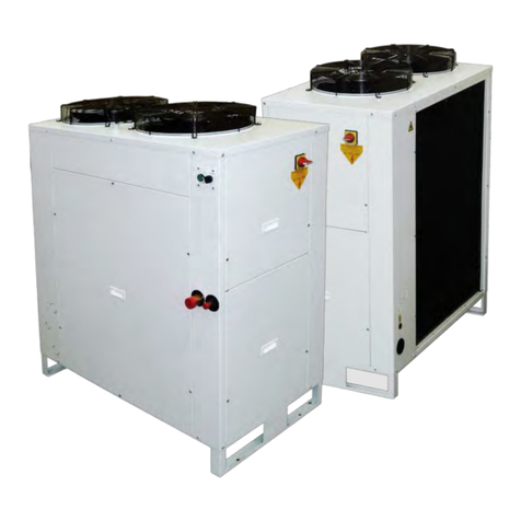
Lennox EMEA eCOMFORT2 User manual

www.lennoxemea.com
eCOMFORT2
20 - 190 kW
AIR COOLED LIQUID CHILLER HEAT PUMP
INSTALLATION, OPERATING
AND MAINTENANCE
MIL160E-0720 07-2020


• 1 •
2
3
4
5
6
1.
1.1 7 - 12
1.2 13
1.3 14
1.4 15
1.5 16 - 18
1.6 19
1.7 20
1.8 21 - 28
1.9 29 - 37
2.
2.1 38
2.2 39
2.3 39
2.4 40
2.5 41 - 42
2.6 43 - 44
2.7 45 - 46
2.8 48
2.9 49
3.
3.1 50
3.2 51 - 52
3.3 53
3.4 54
4.
4.1 55
4.2 56 - 58
4.3 59 - 60
4.4 60
4.5 61
4.5 62
563 - 64
664
Installation manual /eCOMFORT-MIL160E-0720 / 07/2020
TABLE OF CONTENTS
Page
PREFACE
PED DECLARATION
F-GAS REGULATION
WARNING
DATA PAGE FOR UNIT COMMISSIONING
GENERAL CHARACTERISTICS
Technical data
Electrical data
Component
Operation limits
Hydraulic system data
Pressure drop in the water system
Water ow
Piping drawings
Dimensions
INSTALLATION
Transport-Handling
Site and shipping guidance
Unit lifting
Antivibration mounting
Weight distribution
Installation clearances
Unit installation
Electrical connections
Partial Heat Recovery
COMMISSIONING AND OPERATION
Steps to follow for commissioning the units
Steps to ollow for control setting
Checking the water ow rate
Water analysis
MAINTENANCE
Preventive maintenance
Maintenance plan
Cleaning the condenser
Process for replacing a compressor on eld
Corrective maintenance
Failure diagnosis
RISK ANALYSIS AND HAZARDOUS SITUATION ACCORDING TO PED DIRECTIVE
END OF THE MACHINE LIFE

• 2 •
Installation manual /eCOMFORT-MIL160E-0720 / 07/2020
PREFACE
Please read this operating manual prior to commissioning
the eComfort chiller. Familiarize yourself with the operation
and control of the eComfort chiller and closely follow the
instructions.
We would like to stress the importance of training with respect to
the correct handling of the chiller. Please consult Lennox on the
options available in this eld.
It is important that this manual be stored in a permanent location
in the vicinity of the eComfort chiller.
For the sake of clarity, important items in this manual are shown
as follows:
Text Important general instructions
Danger of damage to the chiller
This manual contains important instructions regarding the
commissioning of the eComfort chiller. It also includes important
instructions to prevent personal injury and damage to the
machine during operation. Furthermore, in order to promote
fault-free operation of the chiller, maintenance information has
been included.
Please do not hesitate to contact one of our employees should
you require further information on specic chiller subjects.
Order related documentation will be forwarded under separate
cover. This documentation consists of:
- EU declaration
- Operating manual for control system
- Installation Operating manual
- Wiring diagram
- Unit detail are given on unit nameplate
FOR NETHERLANDS: the STEK logbook, including the required
certicates will be handed over by the installation technician or left
with the machine following commissioning by Lennox. The data
published in this manual is based on the most recent information
available. It is supplied conditional to later modications. We
reserve the right to modify the construction and/or design of
our eComfort chillers, at any time, without prior notication or
obligation to adapt previous supplies accordingly.
Any work on the Chiller should be carried out by trained and
licensed competent technician.
The following risks are present on the unit:
- risk of electrical shock.
- risk of injury from rotating parts.
- risk of injury from sharp edges and heavy weight.
- risk of injury from high pressure gas.
- risk of injury from high and low temperatures components.
Our company’s products comply with European
standards.
The manufacturing of eComfort units answers to
ISO9001 control quality system and to ISO14001.
All the technical and technological information contained in this manual, including any drawing and technical descriptions provided by us, remain the
property of Lennox and must not be utilised (except in the operation of this product), reproduced, issued to or made available to third parties without the
prior written agreement of Lennox.
The specications and technical characteristics in this booklet are given for information purposes. The manufacturer reserves the right to modify them
without prior notice or obligation to modify in a similar manner, the equipments previously supplied.
LENNOX REFAC, SA, in its commient to preserve the environment, has an Environmental Management System based on ISO 14001, through which
all environmental aspects generated during its activity are managed and continuously improved, taking into account the life cycle of the products we
manufacture and market.
For this reason, you: customer, user and / or maintainer of the equipment, are invited to join our commient to conserve our environment, and follow the
indications that we expose throughout this manual.
Original version is the English one. Other versions are translations
Units are certicated by EUROVENT

• 3 •
Installation manual /eCOMFORT-MIL160E-0720 / 07/2020
All units are compliant with the following Directives, Norms and Standards:
• 2014/68/EU Pressure Equipment Directive
• 2006/42/CE Machinery Directive
• 2014/35/EU Low Voltage Directive
• 2014/30/EU Electro Magnetic Compatibility Directive
• EN378-1-2 :2009 -3-4- Refrigerating systems and heat pumps - Safety and environmental requirements
• 2011/65/EU The European Restriction of the Use of Certain Hazardous Substances (RoHS)
• « WEEE », 2012/19/EU –Directive on waste electrical and electronic equipment
• 2009/125/EC Ecodesign • EN-378-1-2:2009-3-4. • EN-60204-1. And is provided with CE markings (on the condition
that the necessary options are present) (for further information see EU declaration).
SAFETY RELIEF
This equipment is protected with safety pressure relief calibrated at 42,7 bar g and safety pressure switch calibrated at 42
bar g. Do not overcome this operating pressure.
IMPORTANT NOTICE
All work on the unit must be carried out by a qualied and authorised employee.
Non-compliance with the following instructions may result in injury or serious accidents.
Work on the unit:
• The unit shall be isolated from the electrical supply by disconnection and locking using the main isolating switch.
• Workers shall wear the appropriate personal protective equipment (helmet, gloves, glasses, etc.).
Work on the electrical system:
• Work on electric components shall be performed with the power o (see below) by employees having valid electrical
qualication and authorisation.
EMC DIRECTIVE COMPLIANCE
WARNING:
This equipment is an “A class“ according CEM Directive. In an industrial environment, this device can create radio electri-
cal noise. In this case, the owner can be asked to take appropriated actions.
This applies to all machine installed with nominal amps below <75A:
• The short-circuit rate Rsce=33 is dened in the EN61000-3-12 standard relative to the harmonics readings on the
supply network. The appliances compliant with the harmonic current limits equivalent to Rsce=33 can be connected in
whatever connection point of the main supply system.
• The maximal allowable impedance of the main supply system Zmax=0.051W is dened by EN 61000-3-11 standard
relative to the voltage variation, uctuation and icker readings. The connection to the supply is a conditional connec-
tion submitted to the preliminary agreement of the power supply local provider.
Work on the refrigerating circuit(s):
• Monitoring of the pressures, draining and lling of the system under pressure shall be carried out using connections
provided for this purpose and suitable equipment.
• To prevent the risk of explosion due to spraying of coolant and oil, the relevant circuit shall be drained and at zero
pressure before any disassembly or unbrazing of the refrigerating parts takes place.
• There is a residual risk of pressure build-up by degassing the oil or by heating the exchangers after the circuit has
been drained. Zero pressure shall be maintained by venting the drain connection to the atmosphere on the low pres-
sure side.
• The brazing shall be carried out by a qualied brazer. The brazing shall comply with the standard NF EN1044
(Minimum 30% silver).
Replacing components:
• In order to maintain CE marking compliance, replacement of components shall be carried out using spare parts, or
using parts approved by LENNOX.
• Only the coolant shown on the manufacturer’s nameplate shall be used, to the exclusion of all other products (mix of
coolants, hydrocarbons, etc.).
CAUTION: In the event of re, refrigerating circuits can cause an explosion and spray coolant gas and oil.
PED DECLARATION

• 4 •
Installation manual /eCOMFORT-MIL160E-0720 / 07/2020
F GAS REGULATION
Operators of refrigeration equipment’s must comply with the obligations dened in:
- EU Regulation No 517/2014 on uorinated greenhouse gases
- EC 1005/2009 on substances that deplete the ozone layer
Non compliance with these requirements is an oence and liable of nancial penalties.
Moreover, in case of problem it is mandatory to prove to the insurance company that the equip-
ment complies with the F gas Regulation

• 5 •
Installation manual /eCOMFORT-MIL160E-0720 / 07/2020
1. Attention: The high-pressure safety switches are essential elements which guarantee the system remains within the
admissible operating limits. Before switching on the installation, always ensure all electrical connections are correct on these
elements which are used to isolate the electrical power supply to the compressor(s) they protect. Carry out a test to ensure
the electrical power supply is eectively isolated when the pressure switch attains its set value.
2. In case of installation in a seismic zone or in a zone which may be eected by violent natural occurrences such as storms,
tornados, oods, tidal waves, etc…, the installer and/or operator will refer to valid standards and regulations in order to ensure
the devices required are available as our units are not designed to operate under such conditions without prior precautions.
3. The equipment is not designed to resist re. The installation site will therefore have to respect valid standards with regard to
protection against re (emergency instructions, map…).
4. In case of exposure to corrosive external atmospheres or products, the installer and/or operator shall take the necessary
precautions to avoid damage to the equipment and will make sure the equipment provided has the necessary and sucient
anti-corrosion protection.
5. To respect a sucient number of supports for the piping according to their size and weight under operating conditions and to
design the piping to avoid a water hammer phenomenon
6. For technical reasons, it is not possible to carry out hydrostatic tests on all our units so leak tests are carried out as a
compensatory measure. (The entire circuit is checked using leak detectors). For machines charged with refrigerant, at the end
of the test, an HP test is carried out in the factory to make sure the pressure switch is working properly.
7. Before any work is carried out on the refrigeration circuit, the dry air or nitrogen pressure our units are supplied with must be
released (For units not charged with refrigerant in the factory.)
8. The emissions of refrigerant via the safety relief valves must be channeled to the exterior of the machine room. The outlet
relief valve will have to be sized in compliance with EN13136.
9. Installation and maintenance of these machines must be carried out by personnel qualied to work on refrigeration equipment.
10. All interventions must be carried out in conformity with valid safety regulations (e. g.: NF EN 378), as well as the recommendations
indicated on the labels and handbooks provided with the machine. All actions shall be taken to avoid access of unauthorized
persons.
11. It is essential that any pipework or other components of the refrigeration circuit hazardous to people because of their surface
temperature are insulated or identied.
12. Ensure that the installation zone (room or area) of the machine has restricted access and ensure the good condition of the
covering.
13. The risk of inadvertent discharge is minimized.
WARNING
WARNING
1.2 - Warning labels
The chiller is marked with the following warning labels to alert to potential hazards (on or near the potentially hazardous part).
Regularly check that the warning labels are still in the correct positions on the machine and replace them if necessary.
High temperatures Electrical Voltage Rotating parts Sharp parts

• 6 •
°C
°C
°C
A
A
A
A
A
A
A
A
Installation manual /eCOMFORT-MIL160E-0720 / 07/2020
DATA PAGE FOR UNIT COMMISSIONING
Unit: Serial no. :
Control panel identication code
Installation address:
Installer: Installer tel. :
Installer address:
Date of commissioning:
Checks:
Supply voltage: Rated voltage of the
unit :
Options Installed:
Comments:
DATA INPUT COOLING CYCLE HEATING CYCLE
Air Input Temperature, Coil
Water Output Temperature
Water Input Temperature
High Pressure
Low Pressure
ELECTRIC POWER CONSUMPTION COOLING CYCLE HEATING CYCLE
Compressor 1
Fan 1
Compressor 2
Fan
Compressor 3
Fan 3
Compressor 4
Fan 4
YES NO
Unit on rubber antivibration mounts
General power supply connection
Control panel connection (option)
Compressor oil level indicator
Hydraulic connection
Purged of the installation

• 7 •
GA C 020 S M 2 M
LNCJ
SEAS
HIFP
ACTR
CPGR
LLWT
PHRF
RLKD
SPLP
DPLP
SPEL
DPEL
SPHP
DPHP
SPEH
DPEH
BYVC
WTNG
WTHS
WTHH
EWFS
WFIF
KGRL
APEP
APPP
APPW
ECLO
BNET
MBUS
MBIP
DM60
DS60
DCBO
ELME
PHCT
POWF
SOFT
EBFM1
EBFM2
ALWA
AVUB
SLCR
Installation manual /eCOMFORT-MIL160E-0720 / 07/2020
1.- GENERAL CHARACTERISTICS
C: Cooling only units
H: Heat pump units
Approximately capacity in kW
S: Single circuit
D: Dual circuit
M: Refrigerant R410A
M: 400V/3/50 Hz
1.1.- TECHNICAL DATA
Type of unit eCOMFORT
2 : Revision 2
OPTIONS
Low noise : Accoustic compressor jacket
Variable air ow control with standard EC fans
Variable air ow control with high pressure EC fans
LenGuard anti-corrosion condenser coil treatment
Coils protection : metallic grille
Low leaving water temperature down to -12°C
Domestic hot water supply : desuperheater
Refrigerant leak detection
Hydraulic module with low-pressure single pump
Hydraulic module with low-pressure twin pump
Hydraulic module with eDrive low-pressure single pump
Hydraulic module with eDrive low-pressure twin pump
Hydraulic module with high-pressure single pump
Hydraulic module with high-pressure twin pump
Hydraulic module with eDrive high-pressure single pump
Hydraulic module with eDrive high-pressure twin pump
Bypass Valve for delta P control with eDrive pump (supplied loose)
Water tank
Water tank electrical heater Standard
Water tank electrical heater High
Electronic ow switch
Water lter (supplied loose)
Flange connection (supplied loose)
Antifreeze protection on exchangers and pipings down to -20°C
Antifreeze protection on exchangers, pump(s) piping down to -20°C
Antifreeze protection on exchangers, pump(s) piping and water tank down to -20°C
LonWorks® interface FTT10
BACnet® interface MSTP
ModBus interface RS485
ModBus and BACnet® interface TCP/IP
Remote advanced display (supplied loose)
Service display (supplied loose)
Remote control : customer drive contact input/output
Electric energy meter
Phase reversal protection
Power factor correction
Soft starter
Electrical box upgrade ventilation : 1 fan
Electrical box upgrade ventilation : 2 fans
Aluminum wires adaptor (supplied loose)
Rubber anti-vibration mounts type (supplied loose)
Wooden crate for long distance
NOTE: When it is possible options supplied loose should be included in a carton box inside the unit

• 8 •
020S 025S 030S 035S 040S 045S 055S 060S 070S 080S
Kw 20,1 24,6 31,7 36,9 40,1 45,5 54,8 61,2 69,5 82,7
2 / Scroll 2 / Scroll
1 1/2” 2”
m3/h 3,5 4,2 5,5 6,4 6,9 7,8 9,4 10,5 12,0 14,2
Kg 312 319 342 366 371 386 602 627 657 706
Kg 4,0 4,2 4,4 4,6 4,8 5,2 7,0 8,0 8,5 10,0
090S 110S 125S 110D 125D 140D 160D 185D
Kw 91,3 106,7 122,3 105,6 123,2 138,8 162 185
3 / Scroll 2+2 / Scroll 2+2 / Scroll 3+2 /
Scroll
2 1/2” 3”
m3/h 15,7 18,4 21,0 18,2 21,2 23,9 27,9 31,8
Kg 876 892 892 989 1000 1401 1508 1575
Kg 12,5 13,5 14,0 13,0 13,6 16,0 16,6 16,8
020S 025S 030S 035S 040S 045S 055S 060S 070S 080S
Kw 20,0 24,4 31,0 36,4 39,4 44,7 54,0 60,1 68,4 81,4
Kw 19,8 24,5 31,9 36,7 39,2 44,6 53,6 61,3 67,6 79,3
2 / Scroll 2 / Scroll
1 1/2” 2”
m3/h 3,4 4,2 5,3 6,3 6,8 7,7 9,3 10,3 11,8 14,0
Kg 335 341 370 394 400 421 645 683 715 773
Kg 7,4 7,6 8,8 9,2 9,4 9,6 14,0 18,0 18,4 19,0
090S 110S 125S 110D 125D 140D 160D 185D
Kw 90,5 105,6 120,4 104,7 121,0 136,5 159,3 181,4
Kw 91,2 103,4 118,1 106,3 121,1 135,8 157,2 174,5
3 / Scroll 2+2 / Scroll 2+2 / Scroll 3+2 /
Scroll
2 1/2” 3”
m3/h 15,6 18,2 20,7 18,0 20,8 23,5 27,4 31,2
Kg 927 995 995 1061 1073 1483 1592 1663
Kg 25,0 27,0 27,3 27,6 29,0 35,0 37,0 38,0
Installation manual /eCOMFORT-MIL160E-0720 / 07/2020
COOLING ONLY
HEAT PUMP
(*) Cooling capacity: Outside temperature: 35ºC / Inlet/outlet water temperature: 12/7ºC
(**) Heating capacity: Outside temperature: 7ºC DB / 6ºC WB / Inlet/water outlet temperature: 40/45ºC
GAC MODELS
Cooling capacity (*)
Number of compressors
Hydraulic connections
Nominal water rate
Net weight
Refrigerant R410A load
GAC MODELS
Cooling capacity (*)
Number of compressors
Hydraulic connections
Nominal water rate
Net weight
Refrigerant R410A load
GAH MODELS
Cooling capacity (*)
Heating capacity (**)
Number of compressors
Hydraulic connections
Nominal water rate
Net weight
Refrigerant R410A load:
GAH MODELS
Cooling capacity: (*)
Heating capacity: (**)
Number of compressors:
Hydraulic connections:
Nominal water rate:
Net weight:
Refrigerant R410A load:
1.1.- TECHNICAL DATA

• 9 •
GAC/GAH 020S 025S 030S 035S 040S 045S 055S 060S 070S 080S
3.5 3.5
18 35
3.5 3.5
100 175
090S 110S 125S 110D 125D 140D 160D 185D
3.5 3.5
35 50
3.5 3.5
GAC: 175 250 400
GAH: 250
GAH
020S / 025S
GAH
030S
Installation manual /eCOMFORT-MIL160E-0720 / 07/2020
1.1.- TECHNICAL DATA
1.- GENERAL CHARACTERISTICS
FAN DATA
HYDRAULIC CIRCUIT
(***) Only in units with Hydronic module
Low pressure pump
Type Stainless steel threaded centrifugal pumps
High pressure pump
Expansion vessel
Type Fixed membrane expansion vessel
Max. pressure (bar)
Volume (dm3)
Buer tank
Type Isolated steel tank
Safety valve set (bar)
Volume (dm3)
Low pressure pump
Type Stainless steel threaded centrifugal pumps
High pressure pump
Expansion vessel
Type Fixed membrane expansion vessel
Max. pressure (bar)
Volume (dm3)
Buer tank
Type Isolated steel tank
Safety valve set (bar)
Voume (dm3)
Airow rate (m3/h) Airow rate (m3/h)
Pressure (Pa)
Pressure (Pa)

• 10 •
GAH
035S / 040S / 045S
GAH
055S
GAH
060S / GAH070S
GAH
080S
Ciśnienie (Pa)
Installation manual /eCOMFORT-MIL160E-0720 / 07/2020
1.1.- TECHNICAL DATA
1.- GENERAL CHARACTERISTICS
FAN DATA
Airow rate (m3/h)
Pressure (Pa)
Airow rate (m3/h)
Pressure (Pa)
Airow rate (m3/h)
Pressure (Pa)
Airow rate (m3/h)
Pressure (Pa)

• 11 •
GAH
090S
GAH
110S / 125S
GAH
110D
GAH
125D
Installation manual /eCOMFORT-MIL160E-0720 / 07/2020
1.1.- TECHNICAL DATA
1.- GENERAL CHARACTERISTICS
FAN DATA
Airow rate (m3/h)
Pressure (Pa)
Airow rate (m3/h)
Pressure (Pa)
Airow rate (m3/h)
Pressure (Pa)
Airow rate (m3/h)
Pressure (Pa)

• 12 •
GAH
140D
GAH
160D
GAH
185D
Installation manual /eCOMFORT-MIL160E-0720 / 07/2020
1.1.- TECHNICAL DATA
1.- GENERAL CHARACTERISTICS
FAN DATA
NOTE: For GAC units consider 3% more of airow
Airow rate (m3/h)
Pressure (Pa)
Airow rate (m3/h)
Pressure (Pa)
Airow rate (m3/h)
Pressure (Pa)

• 13 •
GAC/GAH 020S 025S 030S 035S 040S 045S 055S 060S 070S 080S
kW 9,94 12,22 15,32 17,63 18,21 20,99 25,1 28,00 30,90 35,78
A16,57 18,8 25,79 31,25 30,47 37,05 42,22 47,03 51,84 68,14
A52,11 61,74 88,72 117,96 117,57 147,86 140,56 162,56 167,37 210,54
A34,91 41,14 58,72 77,56 77,17 96,66 93,36 106,56 111,37 140,94
kW 0,24 0,24 0,24 -0,05 -0,05 -0,05 0,48 0,48 0,48 -0,1
A0,2 0,2 0,2 -0,82 -0,82 -0,82 0,4 0,4 0,4 -1,64
kW 1,1 1,1 1,1 0,81 0,81 0,81 2,2 2,2 2,2 1,62
A1,5 1,5 1,5 0,48 0,48 0,48 3 3 3 0,96
kW 0,57 0,57 0,81 0,81 1,35 1,35 1,35 1,35 1,35 1,35
A1,37 1,37 1,59 1,59 2,45 2,45 2,45 2,45 2,45 2,45
kW 1,35 1,35 1,73 1,73 1,73 1,73 1,73 1,73 1,73 1,73
A2,45 2,45 3,15 3,15 3,15 3,15 3,15 3,15 3,15 3,15
kW 2,25 2,25 2,25 2,25 2,25 2,25 6 6 6 6
A3,25 3,25 3,25 3,25 3,25 3,25 8,66 8,66 8,66 8,66
kW 9 9 9 9 9 9 18 18 18 18
A12,99 12,99 12,99 12,99 12,99 12,99 25,98 25,98 25,98 25,98
kW 12 12 12 12 12 12 24 24 24 24
A17,32 17,32 17,32 17,32 17,32 17,32 34,64 34,64 34,64 34,64
GAC/GAH 090S 110S 125S 110D 125D 140D 160D 185D
kW 41,08 48,43 54,88 49,48 57,38 63,2 71,48 84,11
A69,75 81,96 103,35 83,83 96,81 106,48 136,08 149,85
A166,23 197,49 245,75 182,17 212,34 222,01 278,48 292,25
A119,03 141,49 176,15 134,97 156,34 166,01 208,88 222,65
kW -0,1 -0,48 -0,48 -0,1 -0,48 -0,48 -0,2 -0,58
A-1,64 -2,4 -2,4 -1,64 -2,4 -2,4 -3,28 -4,04
kW 1,62 2,08 2,08 1,62 2,08 2,08 3,24 3,7
A0,96 1,2 1,2 0,96 1,2 1,2 1,92 2,16
kW 1,95 1,95 1,95 1,95 1,95 3,28 3,28 3,28
A3,43 3,43 3,43 3,43 3,43 6,24 6,24 6,24
kW 3,28 3,28 3,28 3,28 3,28 4,5 4,5 4,5
A6,24 6,24 6,24 6,24 6,24 7,62 7,62 7,62
kW 6 6 6 9 9 12 12 12
A8,66 8,66 8,66 12,99 12,99 17,32 17,32 17,32
kW 9 9 9 9 9 12 12 12
A12,99 12,99 12,99 12,99 12,99 17,32 17,32 17,32
kW 27 27 27 27 27 36 36 36
A38,97 38,97 38,97 38,97 38,97 51,96 51,96 51,96
kW 36 36 36 36 36 48 48 48
A51,96 51,96 51,96 51,96 51,96 69,28 69,28 69,28
SEAS
HIFP
Installation manual /eCOMFORT-MIL160E-0720 / 07/2020
1.2.- ELECTRICAL DATA
1.- GENERAL CHARACTERISTICS
Maximun power
Maximun current
LRC
Starting current
Starting current with SoftStarter
SEAS FAN
Additional power
Additional current
HIPF FAN
Additional power
Additional current
LOW PRESSURE WATER PUMP
Additional power
Additional current
HIGH PRESSURE WATER PUMP
Additional power
Additional current
ANTIFREEZE ELECTRICAL HEAT
Additional power
Additional current
STANDARD ELECTRICAL HEATER (GAH only)
Additional power
Additional current
HIGH ELECTRICAL HEATER (GAH only)
Additional power
Additional current
Maximun power
Maximun current
LRC(A)
Starting current
Starting current with SoftStarter
SEAS FAN
Additional Power
Additional Current
HIPF FAN
Additional Power
Additional Current
LOW PRESSURE WATER PUMP
Additional Power
Additional Current
HIGH PRESSURE WATER PUMP
Additional Power
Additional Current
ANTIFREEZE ELECTRICAL HEAT (GAC)
Additional Power
Additional Current
ANTIFREEZE ELECTRICAL HEAT (GAH)
Additional Power
Additional Current
STANDARD ELECTRICAL HEATER (only GAH)
Additional Power
Additional Current
HIGH ELECTRICAL HEATER (only GAH)
Additional Power
Additional Current
Variable airow control with standard EC fans
Variable airow control with high pressure EC fans

• 14 •
1 6 11
2 7 12
3 8 13
4 9
14
5 10
8
9
10
11
12 12
12
13
13
1
4
5
6
7
8
9
10
11
12 12
12
14
14
13
13
1´
1
2
3
4
5
6
7
8
9
10
11
12
12
12
11
13
13
14
14
8, 9, 10, 11, 12, 13 4, 5, 6, 7, 8, 9, 10, 11, 12, 13, 14 2, 3, 4, 5, 6, 7, 8, 9, 10, 11,12, 13, 14
Installation manual /eCOMFORT-MIL160E-0720 / 07/2020
STANDARD UNIT
Customer connection
Hydraulic connections
Inside terminal unit
To be connected by the
installer
Carried out by the
installer
UNIT WITH WATER PUMP OPTION
Customer connection
Hydraulic connections
Inside terminal unit
To be connected by the
installer
Carried out by the
installer
UNIT WITH WATER TANK OPTION
Inside terminal unit
To be connected by the
installer
Carried out by the
installer
Hydraulic connections
Customer connection
COMPONENTS:
STANDARD VERSION UNIT WITH WATER PUMP OPTION UNIT WITH WATER TANK OPTION
Water lter (additional option, supplied
loose) Expansion vessel Drain valve
Water tank Water pump Pressure tap
Water tank heater Air purge valve Water temperature sensor
Safety valve Plate exchanger Pressure transducer (when variable water ow
option is selected)
Pressure gauge Flow switch
1.- GENERAL CHARACTERISTICS
1.3.- COMPONENTS
The eComfort system comprises a water cooler or air/water pump combined with a series of hydraulic accessories.
The use of a water lter in the water circuit upstream of the heat exchanger is mandatory. These lters must remove all particles with a diameter greater than 1 mm, and must
be positioned within 1 meter of the inlet of the exchanger. They may be supplied as an option by the manufacturer.

• 15 •
°C
9
8
7
6
5
4
3
2
1
-10 -8 -6 -4 -2 0 2 4 6 8 10
Installation manual /eCOMFORT-MIL160E-0720 / 07/2020
1.- GENERAL CHARACTERISTICS
1.4.- OPERATING LIMITS
Glycol
Variable air
ow control
Variable air ow
control + glycol
Part load
+ glycol
Variable air ow
control
AMBIENT TEMPERATURE (ºC)
LEAVING WATER TEMPERATURE (ºC)
UNITS WITH LOW WATER TEMPERATURE KIT (OPTION)
DIFFERENCE OF TEMPERATURE (water inlet/water outlet)
Maximum dierence of temperature
Nominal dierence of temperature
Minimum dierence of temperature
Water outlet temperature ºC

• 16 •
GAC/GAH
020S - 025S
GAC/GAH
030S - 035S
GAC/GAH
040S - 045S
GAC/GAH
055S - 060S
Installation manual /eCOMFORT-MIL160E-0720 / 07/2020
1.- GENERAL CHARACTERISTICS
1.5.- HYDRAULIC SYSTEM DATA
WATER FLOW AND AVAILABLE STATIC PRESSURE OF WATER PUMP
Pressure (kPa)
Pressure (kPa)
Pressure (kPa)
Pressure (kPa)
Water ow rate (m3/h) Water ow rate (m3/h)

• 17 •
GAC/GAH
070S / 080S
GAC/GAH
090S
GAC/GAH
110S / 125S
GAC/GAH
110D / 125D
Installation manual /eCOMFORT-MIL160E-0720 / 07/2020
1.- GENERAL CHARACTERISTICS
1.5.- HYDRAULIC SYSTEM DATA
WATER FLOW AND AVAILABLE STATIC PRESSURE OF WATER PUMP
Pressure (KPa) Pressure (kPa)
Pressure (kPa)
Pressure (kPa)
Pressure (kPa)
Water ow rate (m3/h)
Water ow rate (m3/h) Water ow rate (m3/h)

• 18 •
GAC/GAH
140D / 160D
GAC/GAH
185D
Installation manual /eCOMFORT-MIL160E-0720 / 07/2020
1.- GENERAL CHARACTERISTICS
1.5.- HYDRAULIC SYSTEM DATA
WATER FLOW AND AVAILABLE STATIC PRESSURE OF WATER PUMP
Water ow rate (m3/h) Water ow rate (m3/h)
Pressure (kPa)
Pressure (kPa)
Table of contents
Other Lennox EMEA Heat Pump manuals
Popular Heat Pump manuals by other brands

ClimateMaster
ClimateMaster TYH/V 024 - 060 60Hz - HFC-410A Installation, operation, & maintenance instruction

Bryant
Bryant LEGACY 677C E Series installation instructions

Trane Technologies
Trane Technologies 4TWV8049A1000B manual

Daikin
Daikin EKHBX008BA installation manual

Payne
Payne 541B owner's manual

Dimplex
Dimplex LA 33TBS Installation and operating instructions