BARGAM AT Biturbo Series User manual

1
MAINTENANCE & USE OPERATOR’S MANUAL
TRAILED SPRAYERS
AT Biturbo , AT Pneus , AT , AT Vigne ,
AT Fruits , Turbo AT, Super AT Biturbo,
Super AT, AET
MOUNTED SP
RA
YE
R
AP PNEUS, AP70 , AP50 , Turbo AP45 , Turbo AP45 flex , Turbo AP35
LOW VOLUME SPRAYERS mod. : “PNEUS”
SPRAYERS WITH DIRECTIONAL CANNON HEAD mod. : “FLEX”
WEED KILLING AND SPRAY GROUP :mod: AP for weed killing booms,spray
booms , electric sprayers
CAREFULLY
READ
THE
INSTRUCTIONS
BEFORE
START
USING
THE
EQUIPMENT
Via della Cooperazione,20- 40026 Imola (BO) ITALY
Tel. +39(0542)648511 Fax +39(0542)640539
www.bargam.com - e-mail: sales@bargam.com

2
DIMENSIONS AND WEIGHTS TABLE
MODEL
C
APA
C
I
T
Y
L
T
W
I
D
TH
M
M
L
E
N
G
H
T
M
M
H
EI
G
H
T
M
M
W
E
I
G
H
T
K
G
AT 660
600
1100
2300
1160
550
AT 1100 1000 1150 3080 1195 690
AT 1650 1500 1350 3140 1500 750
AT 2200 2000 1400 3600 1400 780
AT 3300 3000 1800 4000 1500 930
AET 660 600 1100 2300 1160 440
AET 1100 1000 1150 3080 1195 550
AET 1650 1500 1350 3140 1500 750
AET 2200 2000 1400 3600 1400 780
AT PNEUS 660 600 1100 2300 1100 440
AT PNEUS 1100 1000 1150 3080 1150 550
AT PNEUS 1650 1500 1350 3140 1350 690
AT PNEUS 2200 2000 1400 3600 1400 780
AT BITURBO 1100 1000 1150 3580 1200 600
AT BITURBO 1650 1500 1350 3640 1500 740
AT BITURBO 2200 2000 1400 4100 1400 800
AT BITURBO 2200 2000 1400 4100 1400 830
AT BITURBO 3300 3000 1700 4500 1500 980
AT FRUITS 1100 1000 1150 3080 2150 570
AT FRUITS 1650 1500 1350 3140 2150 690
AT FRUITS 2200 2000 1400 3600 2200 780
AT FRUITS 3300 3000 1700 4000 2800 930
AT VIGNE 660 600 1100 2300 1160 440
AT VIGNE 1100 1000 1150 3080 1195 550
AP70 330 300 1000 1235 1070 207
AP70 440 400 1000 1235 1200 227
AP70 440 400 1000 1235 1200 237
AP70 660 600 1410 1260 1220 247
AP70 660 600 1410 1260 1220 247
AP70 880 800 1410 1260 1430 267
AP70 1100 1000 1410 1260 1590 300
AP50 220 200 1000 1235 910 193
AP50 330 300 1000 1235 1070 203
AP50 440 400 1000 1235 1200 228
TURBO AP45 440 400 1300 1000 1200 341
TURBO AP45 660 600 1420 1410 1220 423
TURBO AP45 880 800 1420 1410 1430 435
TURBO AP45 1100 1000 1420 1410 1590 443
TURBO AP35 330 300 1210 1000 1150 262
TURBO AP35 440 400 1210 1000 1300 276
TURBO AP35 660 600 1260 1410 1350 290
TURBO AP45 FLEX 440 400 1550 1400 1900 444
TURBO AP45 FLEX 660 600 1550 1400 1900 526
TURBO AP45 FLEX 880 800 1550 1400 1900 538
TURBO AP45 FLEX 1100 1000 1550 1400 1900 546
SUPER AT BITURBO 2200 2000 1600 3800 2300 1030
SUPER AT BITURBO 3300 3000 2400 4200 2400 1180
SUPER AT 2200 2000 1600 3800 2300 980
SUPER AT 3300 3000 2400 4200 2400 1130
TURBO AT 1100 1000 1150 3080 1195 700
TURBO AT 1650 1500 1350 3140 1500 820
TURBO AT 2200 2000 1400 3600 1400 910
TURBO AT 3300 3000 1700 4000 1500 1060
AP PNEUS 330 300 1000 1400 1070 207
AP PNEUS 440 400 1000 1400 1200 227
AP PNEUS 660 600 1410 1400 1220 247

3
INTRODUCTION
This manual describes the performances and the operations with necessary instructions
for proper use and periodic maintenance of the equipment.
This manual is divided into chapters for an easy consultancy.
The information contained in this manual is intended for a professional user, who must
have specific knowledge about how to use the machine and must be authorized and
trained.
We recommend the use of original spare parts and accessories. Not original parts could
invalidate the warranty, might be dangerous and might reduce the life duration and the
performance of the machine.
In case of transfer or sale this manual must always be delivered with the machine. If it is
damaged
or
los
t, a copy can be asked the supplier or previous owner. The manual is
considered as part of the equipment.
GENERAL WARRANTY CONDITIONS:
a) To the extent the following provisions, the Seller warrants solely to Buyer that the goods
sold are free from defects on material, design, manufacture and assembly in relation to the
level of technical development at the time of construction. This undertaking is limited to
defects that occur during the period of 12 months from the date of the delivery .
b) Ending the standard warranty (12 months), the term of the same effect may be delayed
up to a maximum of six months by BARGAM S.p.A. to the Buyer , if the produced goods
are not immediately sold. In this case, the warranty starts from the moment that the Buyer
delivers the equipment to the third parts (Purchaser). The Buyer must inform BARGAM
S.p.A. that the equipment was sold to the end-users .This obligation is considered fulfilled
when the Buyer sends to BARGAM S.p.A. the warranty
dra
ft that can
be
f
ound
on the
web site “www.progroup.it " completed in any part. In any case, the guarantee
provided by BARGAM S.p.A. is valid and effective ever and only for the Buyer and cannot
be relied on by t
he
la
t
es
t.
c) BARGAM S.p.A. does not guarantee services and / or workmanship of engines
mechanisms and diesel equipment, electrical and thermal (but not limited to tires, fuel
injection system, engine, differential axle, bearings, hydraulic shares, ...) sold
individually or simply assembled by the Seller. In this case the warranty is limited to the
warranty period given by the OEM and contained in the technical documentation
provided by BARGAM S.p.A. to the Buyer upon delivery. Buyer declares his
acknowledge and acceptation
o
f t
he
guarantees issued by these manufacturers.

4
d) The warranty will be valid if the claims and / or defect will be sent within 8 days in
writing form to the manufacturer .
e) The Purchaser shall be waived in any case by the warranty:
-If the vices and / or defects depend on normal wear and tear of the property;
-If the goods delivered is subjected to improper use or use higher than expected from the
contract and the documentation provided with the products;
-If the defects are derived from an assemblage made by the Purchaser that is not in
accordance with the instructions contained onto the manual "Instructions for Use";
-If it does not perform periodic maintenance procedures and strictly in accordance with the
schedule proposed by the Seller;
-If, in the event of any faults and defects, repair and / or replacement of defective parts is
not addressed to the Seller;
-If it does not meet the deadlines of payments.
f) The guarantee provided by BARGAM S.P.A. consists solely of the repair and / or
free replacement of parts and / or parts that present defects and / or defects, with the
express exclusion of the guarantees contained in Articles. 1490, 1492, 1497, 1512 of the
Italian Collection of rules and, as well as the
aliud
pro
alio and the obligation to
indemnify any direct or indirect, immediate or mediate, resulting from defects and
/ or defects themselves. No other recognition will be made as security for labour,
transportation, various interventions, etc.., insofar as they are considered part of the
trade discount granted.
g) The Buyer must send back the defective goods to the BARGAM S.p.A. and the latter
may choose whether the repairing or replacement thereof options. The bonds are
considered the BARGAM S.p.A. fulfilled by
delivery
t
o
Purchaser of the repaired or
replaced goods.
h) In the event that the BARGAM S.p.A. send products to replace the defective ones
before the receipt of the latter, the buyer must return the tainted products to the
Producer within 15 days of receipt of those substitutes. The goods become the property of
the producer itself. If the Purchaser, except as writing authorized by BARGAM S.p.A.,
does not return the defective products within the mentioned period shall be required to pay
the replacing of the products
i)The costs and risks of shipping the defective product from Buyer's premises to the
headquarters of the BARGAM S.p.A. and the cost of repairs made outside of
establishments BARGAM S.p.A., will be borne by Buyer. Similarly, even the return
cost and the risks of transporting the goods repaired or replaced from the BARGAM
S.p.A. will be at purchaser costs.

5
TABLE OF CONTENTS
1 ABOUT THIS MANUAL
1.1 UPDATING THE MANUAL
1.2 COPYRIGHT
1.3 CE MARKING PLATE
1.4 INFORMATION ON THE MACHINE
1.4.1 INTENDED USE
1.4.2 DESCRIPTION
1.5 STORAGE
1.6 FIRST USE OR USE AFTER LONG PERIOD
1.7 DISASSEMBLING
1.8 SAFETY AND ACCIDENT PREVENTION
1.8.1 PESTICIDES
1.8.2 FIRE-FIGHTING MEASURES
1.9 SAFETY SIGNS
1.9.1 LOCATION OF THE MACHINE PICTOGRAMS
1.9.2 DESCRIPTION OF PICTOGRAMS
2 TRANSPORT AND HANDLING
3 TRANSPORT ON PUBLIC ROAD (only for approved machine)
4 OPERATION OF THE MACHINE
4.1 HYDRAULIC SYSTEM
4.1.1 MAIN TANK
4.1.2 CIRCUIT CLEANING TANK
4.1.3 HAND WASHING TANK
4.1.4 SUCTION FILTER & “3 WAY”GATE
4.1.5 PUMP
4.1.6 HIGH PRESSURE FILTER
4.1.7 MIXERS
4.1.8 CONTROL UNIT
4.1.9 DISTRIBUTORS
4.1.10 NOZZLES
4.2 PNEUMATIC SYSTEM
4.2.1 IMPELLER
4.2.2 GEAR BOX
4.3 WORKING ADJUSTMENTS
4.3.1 ORIENTATION OF THE AIR FLOW
4.3.2 SETTING PRESSURE HYDRAULIC SYSTEM OF WORK
4.4 CRITERIAS FOR CHOOSING & ADJUSTING THE WATER FLOW
4.4.1 SPRAYERS WITH AXIAL FAN
4.4.2 SPRAYERS WITH FAN GUN
4.4.3 LOW VOLUME SPRAYERS
4.4.4 GROUPS AND SPRAY HERBICIDE: HERBICIDE BOOMS, LANCES, ELECTRIC IRRORATOR
4.5 CALIBRATION OF MACHINE
4.5.1 MAX LIMIT OF CONCENTRATION OF PLANT PROTECTION PRODUCT USED
4.5.2 INTENSITY 'OF COVERAGE
4.5.3 INDEX LEAF COVERAGE
4.5.4 DEGREE OF SPRAYING
4.5.5 MINIMIZE THE DISPERSIONS
4.5.6 EFFECTIVENESS AND NOZZLE ORIENTATION
4.5.7 ORIENTATION AND EFFECTIVENESS OF AIR OUTLETS
4.6 MIXING
5 CORRECT OPERATION OF THE MACHINE
5.1 CLEANING FILTERS
5.2 CHECKING OF PROGRESS’SPEED
5.3 OPERATE IN ENVIRONMENTAL GOOD CONDITION NELLE CORRETTE CONDIZIONI AMBIENTALI
5.4 CHECKING OF THE GEARBOX OIL LEVEL
5.5 CHECKING OF THE RESERVOIR LEVEL
5.6 CHECKING OF MANOMETER
6 CONNECTION TO THE MACHINE
6.1 CONNECTION OF THE MACHINE TO THE TRACTOR
6.2 DISCONNECTION OF THE MACHINE FROM THE TRACTOR
7 MAINTENANCE
7.1 OPERATOR’S MAINTENANCE OPERATION
7.2 GREASING
7.3 CHECK OF OIL LEVEL : GEARBOX
7.4 REPLACEMENT OF OIL ON GEARBOX
7.5 CHECKING OF TURBINE
7.6 CHECKING OF THE NOZZLES
7.7 CHECKING OF THE FILTERS
8 TABLE OF SCHEDULED MAINTENANCE
9 TABLE OF TROUBLES RESEARCH
10 SPARE PARTS

6
1 ABOUT THIS MANUAL
This manual is an integral part of the machine and must accompany it in
case of resale and until its demolition.
In case of loss or damage of this Manual please request a copy to the manufacturer (IMA.
IT S.p.A. via Gambellara 10 Imola BO ) or retailer ( )
insert name and address of the retailer
This manual should be translated into the language of the country where the machine is
sold .
On equipment are suitable some pictograms which have to be maintained in a perfect
condition and replaced when they are no longer legible by the operator.
The presence of this symbol means to pay close attention to the item
described
It would be possible that some devices described in this manual are missing on your
machine, depending on fittings and/or market features based on machine destination.
1.1 UPDATING THE MANUAL
The information, descriptions and illustrations in this manual reflect the state of the art
when
machine
has
been commercialised .
The manufacturer reserves the right to make, at any time, any changes to the machines
for technical or commercial reasons. These changes do not require at manufacturer to act
on sold equipment to update it or to consider it inadequate.
Any additions that the manufacturer deems appropriate to provide, it need to be stored
together with the manual and has to be considered an integral part of it.
1.2 COPYRIGHT
The copyright of this manual belongs to the manufacturer. This manual contains text,
drawings and technical illustrations that cannot be disclosed to third parties or transmitted,
in whole or in part, without the written permission of the manufacturer of the machine.

10
1.3 CE PLATE
The CE plate is positioned in front of the machine near the drawbar (if trailed model) or
positioned t
o
t
he
3 Point Hitch (if mounted model)
It indicates:
- Brand of the manufacturer
- Company name and address of
manufacturer
- Type and model of equipment
- Weight
- Serial identification number
- Year of construction
1.4 INFORMATION ON THE MACHINE
1.4.1 INTENDED USES
The machine "sprayers " is designed exclusively for the distribution of pesticides .
The sprayers are machines intended for pesticide, fungicides and others phytochemical
treatments.
Their function is to spray the mixture in aqueous solution and conveys it to the crop , made
by nozzles
and
air
flow, produced by a fan, that brings the drops on the leaves.
The machine should be operated by a single operator inside the cab of the tractor.
The operator using the machine must be familiar with all the instructions contained in this
manual.
The machine has been designed and built to operate outdoors, because its performance is
affected by the weather conditions.
The machine "sprayer" described in this manual complies with the European directive
200642CE and subsequent modifications and integrations and therefor it is equipped with
CE mark.
Every different use of the machine is considered unauthorized and
dangerous.

11
1.4.2 DESCRIPTION
The Fan air sprayers are popular: the liquid is brought out of the tank, using a pump to the
nozzle where it is hit by a strong air current speed produced by a fan (centrifugal or axial).
For optimal spraying the air flow should be smoothed e.g. against-propellers or conveyors.
The quantity of product depends on the number and extent of the nozzles.
In this way it will reach a diameter of droplets between 100 and 300 microns.
The machine consists of:
-Mounted Frame to connecting to the tractor rear lifting arms (for mounted unit models ).
-Frame with drawbar to connecting the rear hitch of the tractor (for trailed models).
-Main polyethylene Tank (4.1.1)
-Polyethylene system washing tank (4.1.2)
-Polyethylene hand-washing tank (4.1.3)
-Suction Filter (4.1.4)
-Pump (4.1.5)
-High pressure Filter (only trailed Models) (4.1.6)
-Control unit (Par 4.1.9)
-Nozzles (Par 4.1.10)
-Axial or centrifugal impeller (4.2)
1.5 STORAGE
If the machine is stored for long periods it is necessary to store it in a place protected
against atmospheric agents and protect it to avoid damage.
Verify that the storage temperature is between
0
°C and 50°c.
Do not place the machine on the ground sloped or excessively saggy.
The machine is designed to be parked safely on compact soil with slopes of up to 8.5°.
In order t
o
prepare
the machine for the storage it is necessary to proceed to a thorough
cleaning of the tank and hydraulic circuit with the same procedure used at the end of
treatment..
In addition , it’s necessary to:
completely empty the water circuit to avoid damage caused by frost.
Mix with clean water a liquid anti-freeze to protect not only the pump but also all
components in contact with the liquid (command groups, Jet holder and filters).
Remove and clean the filters and nozzles which must be kept in a secure
environment
by
weathering.
cancel the pressure inside the hydro-pneumatic compensator of the pump
Grease the moving metal parts.
Repaint all surfaces that could rust, where necessary..
place the machine in a ventilated place sheltered from rain and Sun..

12
1.6 START UP OR RESTART AFTER LONG PERIOD OF INACTIVITY
Before using the machine for the first time or after a long period of inactivity you must do
the following:
check that the machine does not present any damage.
Check that the machine is correctly mounted in its entirely.
Check the mechanical parts, which must be in good condition and not rusted..
Check that the suction filter and tank inside are clean and free of residues.
Check that the connections are mounted correctly by following the basic schema.
check that the tube straps are tight correctly as all fittings and connections..
ensure that the gear box is suitably replenished of lubricant
check that the fan is free to rotate and that the box is not deformed by blows
received
during
transport..
check and, if necessary, restore the oil level of the pump.
Grease transmissions and mechanical joints.
Ensure the presence and functionality of protective devices.
check the status of the pump and the hydraulic compensating.
make sure that all the nozzles are in good condition, with no obvious signs of wear
and fouling.
check the status of all hoses and replace them if necessary.
check tightness of all bolts of the machine.
Remove the cardan shaft from the machine and lubricate it.
1.7 SCRAPPING
In case of scrapping the machine must be disposed in adapted landfills according to the
current legislation.
Before scrapping it is necessary to separate the plastic or rubber parts, electrical and
electronic material.
Before scrapping the equipment thoroughly washing inside and out. Unloading of washing
compounds
in
t
he
environment without precautions is banned due to groundwater
pollution.
Recover any waste oil and dispose of it in the special collection centers.
used oil must be properly recovered and must not be dispersed in the
environment, because, according to the current regulations, is classified
as hazardous waste
a
nd i
t
should be awarded to special collection
centers.
For the collection of waste oil, it is mandatory to consult the local norms of Oils residual.
The parties constituted only by plastic, aluminum, steel, can be recycled.

13
1.8 SAFETY AND ACCIDENT PREVENTION REGULATIONS
A correct use of the machine, a scrupulous compliance with the rules listed here
and the strict enforcement of all precautions to prevent dangerous situations, will
prevent risks of accidents or injury, a better and longer work of machine and
minimise failures.
The BARGAM S.p.A. declines all and every responsibility objective and subjective
when the behavioral norms described on this manual are not applied
Machine is not suitable to be used in sectors other than agriculture.
Machine must be used by a single operator inside the cab of the tractor.
A different use from the one specified is considered improper.
Machine must only be used by authorized, trained and properly trained operator.
The operator after reading and assimilating the instructions contained in this
manual must get adequate preparation on the proper use of the machine and must
be in possession of driving license. Please remember to contact the manufacturer
in case of doubt about the use of the machine and on the interpretation of this
manual.
The manual must be always closed to be easily consulted to verify the operating
cycle. If it is lost or damaged you must request to BARGAM S.p.A. a copy.
The operator must be ensured that, during the operation no person or animals are
within working range. Never operates the machine near any people standing
closed or transiting within the working area of machine.
Do not use the machine if you are tired, ill or under the influence of
alcohol, medicines or drugs..
This machine is usually used during the day, if it is requested, exceptionally, to
use it at night or in reduced visibility condition it should be used with lighting
system of the tractor or an auxiliary lighting system mounted onto equipment .
Any arbitrary modification made at this machine indemnifies and keep indemnified
BARGAM S.p.A. from any liability for damages or injury which may result to
operators, third parties and things.
Verify carefully the machine before each start up.
BARGAM S.p.A. cannot cover any improper use which can cause a potential danger
The signs applied to the machine provides important notices, their full
compliance are important for your safety.
Be sure all safety pictograms are legible. Clean and replace them if necessary
with new labels.
before using the machine make sure that all safety devices are placed correctly in
place and in good condition; If you experience failures or damages to replace
them immediately..
Before go down from the tractor and before every maintenance operation actuate
the parking brake, stop the engine and remove the ignition key from the
dashboard
Staff should use the safety equipment and personal protective equipment during
the use and maintenance of the machine.
It is recommended that the machine operator not to wear clothing that can give
rise to snagging.
It is necessary that the operator is equipped with suitable dust mask for
respiratory protection.

14
During working operations the operator must have sufficient visibility on areas
deemed dangerous so it makes sense to keep clean and in very good condition
mirrors that is equipped with the tractor..
Machine must not be left unattended with the engine of the tractor in motion or
ignition key inserted.
keep the machine clean from foreign matter (debris, tools, miscellaneous items) that
could damage the functioning or cause damage to the operator.
When the machine is stopped on sloping ground, use the parking brake and locking
wedges supplied with the machine.
do not operate on muddy soil, sandy or saggy..
check the state of art of the hydraulic hoses. In case of deterioration (or at least
every year) is recommended to replace them.
Do not use controls unit or hydraulic hoses as handholds. These components are
mobile and do not offer stable support.
Any modification of the machine art may cause security issues. In this case the user
will be solely responsible for any accidents.
It is strictly prohibited to remove or tamper with the safety devices..
Be sure of the good condition of the pictograms. If the pictograms are damaged must
be replaced with other to require to the original manufacturer and replaced in the
position indicated by the use and maintenance manual (section 1.9.1)
Normally, the machines are not designed for road use. Road traffic is allowed if the
machine is equipped with special accessories (e.g. self-reflective signs, flashing
lights, rear lights, etc ...) and when connected to tractors which comply with country
regulations.
In case of circulation on public roads, be sure you the tank is free of any chemical
inside it.
Before travelling on public roads, put the machine in transport position, in
accordance with the manufacturer's indications.
It is strictly prohibited the transport of persons on the machine.
The coupling of the machine to the tractor, shall be exclusively performed on
attachment points provided for this purpose in accordance with the safety
regulations in force.
Before connecting the machine make sure the weight of the front axle of the tractor is
sufficient. The laying of the ballast masses must be made on the supports provided for
this purpose in accordance with the rules of the manufacturer of the tractor. The load
on the front axle of the tractor, must not be less than 20% of the sum of the kerb
weight of the tractor and the operator.
pay attention to the risk of unintentional contact of parts of the machine with the
high voltage airlines.
Perform the turns prudently, taking into account the overhang, the length, the height
and weight of the machine.
Do not use a PTO shaft without adequate protections in accordance with legal
requirements.
Do not transit, stay or work between the tractor and the machine.

15
before starting the tractor's engine, make sure all controls are in neutral position
before you engage the PTO, check that the fan protection network is present and
well fixed and that the gearbox is in neutral position.
Keep always clean the area of movement of the impeller, removing foreign objects
both outside and inside the security network.
do not commute with the impeller running outside of those necessary for spraying
pay attention for any person or animal is closer to the fan when this is running.
After the PTO disengagement, moving elements can still turn a few seconds. Do not
approach until it stops.
1.8.1 PLANT PROTECTION PRODUCTS
Spraying is a delicate operation and involves substantial risk of contamination of people,
animals and the environment. It is very important to treat the functionality of all the parts of
sprayer;
The operator is always the subject more exposed to chemicals used and must work using
all measures necessary for his safety;
It is important to operate under the right weather conditions and inquire about the weather
for the entire period of application;
measure accurately the doses of pesticides to enter in the main tank;
Make sure that the chemicals used are compatible with the materials of construction of the
atomizer;
Never leave chemicals in the tank for more than a few hours;
Carefully follow the rules of detention and use of plant protection products on the market
and ensure that people and animals cannot touch them;
Before each treatment, thoroughly wash the containers of chemical liquid/powders
Do not use the machine without water tank for hand washing or if the same is not
completely fill up;
It is advisable to clean the machine at the same place in which you perform the fills or in a
square where the waters are collected in a pit for disposal;
Avoid uncontrolled discharge of mixing waste on streams, sewers and public areas;

16
1.8.2 FIRE-FIGHTING MEASURES
The machine is built with wide use of materials derived from petroleum, moreover, the
presence of various types of oil and chemical residues make them potentially flammable
Keep on the tractor's
-board
an
extinguisher of adequate capacity and provide periodic
recharge. The hand fire extinguisher use is reserved to staff able to use it.
It is recommended that the operators staff is aware of the major technics of operations in
case of fire;
All fuels and most of the lubricants and hydraulic fluids are flammable;
Do not smoke when refuelling or restore fluid level, do not make supplies near an open
flame, do not transfer the fuel;;
Never use gasoline, solvents or other flammable or toxic fluids for cleaning mechanical
parts: use approved commercial solvents that are non-toxic and non-flammable;
Do not perform welding operations near reservoirs, pipes, tanks, electrical wires or
inflammable materials;
In case of welding protect with suitable screens flammable parts.
1.9 SAFETY SIGNS
Make sure of the good condition of the pictograms. If the pictograms are damaged must be
replaced with other required by the original manufacturer and placed in the position
indicated by the use and maintenance manual.
Make sure the safety pictograms are legible. Clean it using a cloth, soap and water.
.1.9.1 LOCATION OF PICTOGRAMS ON THE MACHINE
On mounted sprayers, safety pictograms are
located laterally on main tank
.
On trailed sprayers, the adhesives are
placed near the drawbar.

17
1.9.2 DESCRIPTION OF PICTOGRAMS
1 CAUTION : adjustment operations and
maintenance must be carried out after
reading the user's manual, with the
machine stopped and off key.
2. CAUTION -DANGER of fluids under
pressure. Read the manual before
intervening and in case of injury, seek
medical advice.
3. CAUTION-DANGER this machine must
be used by a single operator.
4. CAUTION-do not climb or get carried
by the machine.
5. WARNING -danger of shearing..
6. WARNING -DANGER poisonous
products to touch and aspirate..
7. WARNING -DANGER maximum
working pressure.
8. ATTENTION-DANGER do not
introduce yourself in the tank.
9. CAUTION –danger -tube pressure,
refer to the owner's manual
18
10. WARNING -danger of entanglement
and dragging. Do not bring your hands to
the transmission shaft in motion.
11. WARNING -DANGER rotating parts.
12 CAUTION-danger of electrocution.
During use of the machine pay maximum
attention to overhead power lines.
13. WARNING –crushing hazard -do not
stand below the machine arms
14. Use required personal
protective equipment ..
15. GREASING POINTS
16. OIL TANK
17. LIFTING POINT

19
2 HANDLING AND TRANSPORT
Place the maximum attention to safety during the loading and unloading operations which
must be carried out by qualified personnel ( truck operators, etc.).
When lifting the machine it is important to use the appropriate lifting eyes indicated by
pictograms..
The presence of this sticker on the machine indicates a:
ATTACHMENT POINT FOR LIFTING HOOK
To transport the machine, it’s important to use a means crafted.in power and size,
3 TRANSIT ON HIGHWAY (only for homologated machines )
case you need to follow a highway ,it's necessary to abide yourself strictly
to the rules of the road taking particular care with any requirement noted in
the booklet of the machine and the choice of appropriate speed. The firs
step during the circulation is to install any optional light bars, self-
reflecting signs etc ....
It is mandatory to provide the machine of flashing yellow light..
The weight of the modified machine changes the stability of the whole tractor-atomizer,
influencing the ability of steering and braking, for this reason it is necessary to proceed at
moderate speed.
4 MACHINE OPERATION
Make sure that during the work, all parts of the machine work regularly.
Point out that most of the accidents and damages that may occur during
use of the machine are caused by the loosening of the fastening
elements.
As in the first phase of the life of the machine is produced an overall settlement of all
mechanical and hydraulic connections ,it is essential to carry out the controls of the
machine with maximum accuracy.
Before using the machine make sure that within the range of the machine there are no
people or animals.
Make sure that no person or animal are in near of ventilators when this is running.
The machine must be used by a single operator inside the cab of the tractor.
It is absolutely forbidden to remove and/or change the protections on the machine..

20
Do not use the machine when tired, ill or under the influence of medication, drugs or
alcohol..
Before using the machine it is necessary to learn the layout of controls and operation..
Pay attention to the risk of unintentional contact of parts of the machine with the high
voltage airlines.
4.1 PLUMBING
4.1.1 MAIN TANK
The main tank has various capacities. To fill the water tank use only indirectly open
waters or just free-fall from water conductor.
You can fill the tank through the pump using the pick-up filter (p. 4.1.4)
The tank is equipped with a graduated band that brings transparency to the exact
quantity
o
f
liquid
inside. The detection has to be made in flat area .
All filling systems provided by BARGAM S.P.A. are preventing pollution and
regurgitation of liquid inside the tank
4.1.2 WASHING- SYSTEM CIRCUIT TANK
All mounted and trailed sprayers are equipped as per CE directive
n
°2004/108 of
circuit-washing tank to cleaning the whole machine (suction pump delivery, nozzles).
The tank must be filled only by clean water.
To use the circuit-washing tank for cleaning it is enough to turn the 3-way gate valve on
CIRCUIT-WASHING TANK position and operate the pump for 10 min.
When done, it's necessary to eliminate waste in defined places where they cannot
cause harm to people or to the environment.
Use different active ingredients on various crops to avoid damage .We recommend to
add to each washing liquid 2 kg of soda for every 100 liters of water.
4.1.3 HAND-WASHING TANK
For the cleaning of the operator, when using the machine or when it is necessary, is
installed a tank of variable capacity according to the main tank. The clean water tank
for hand washing has to be filled only by clean water.
Do not drink for any reason the liquid inside!
21
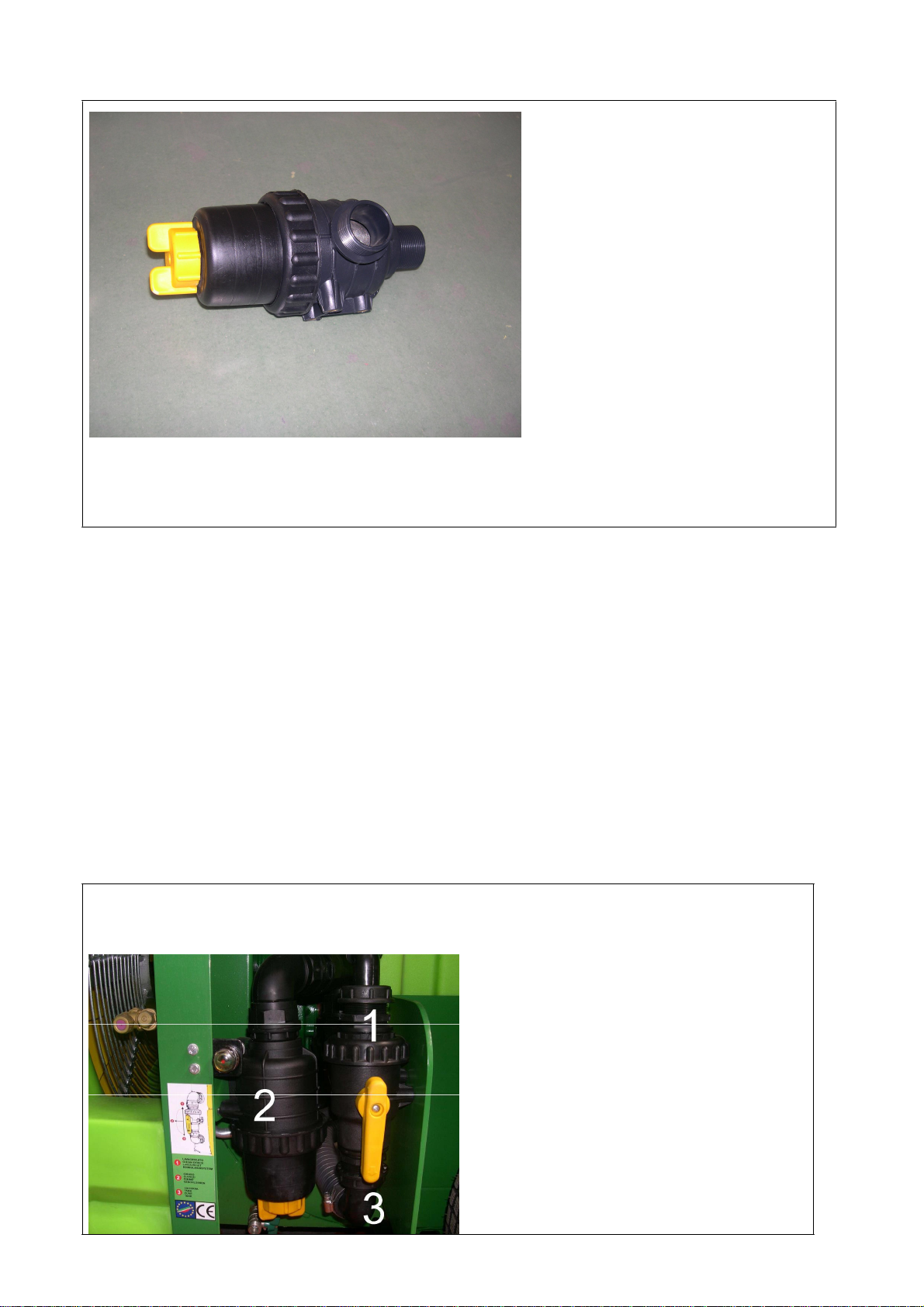
4.1.4 SUCTION GATE AND 3 WAYS VALVE
The inlet filter allow to fill
the tank from external
sources (wells, streams,
etc..).Filters assembled on
equipment have 50 mesh
cartridges of 0.3 –0.4 mm
(pos. 3).
The filter must be frequently
checked while with a good
cleaning of these you get a
smooth operation of the
machine.(§:7.7)
If the liquid used in the treatment has
many impurities, it is good practice to
clean them each
tank’s filling. Always remember do not
clean the filter with the pump on and to
wear appropriate safety clothing. Before removing the filter cap (POS.
7) make sure that the same is isolated from the pipe by turning the
appropriate gate valve or the 3 -way diverter. After washing the cartridge
replace the cover reconnecting it to the circuit.
To use the suction filter:
remove the throttle valve on the bottom of the suction strainer (POS. 8)
tighten the rubber door fitting the bottom filter thread (POS. 7)
connect the rubber pipe from 6 yards with floating filter on
place the pressure regulator on exhaust position
action the pump
check the water level in the tank
switch off the pump and disconnect the tube from the suction filter
“3 WAY GATE VALVE
The 3-way gate valve permits to direct, inside the loop, the liquid in various directions
- During spraying in the field the level
should be placed in position 1.
- During the filling phase from wells or from
the external tanks, it can take any position.
- During the tank and circuit washing (at
the end of each treatment, chemical liquid
change or when it has required for the
periodic maintenance ), the lever must be
placed in position 3.

22
4.1. 5 PUMP
A pump is installed on the machine
according to the models .The pump manual
is enclosed to t
his
manual
. We recommend
to read both carefully . Be very careful with
the data reported by the manufacturer.
The pump can be identified from the data
plate applied on it; the main data of
pressure and f
low
are
easy to find. Normally
the pump must not exceed 550 rpm; a
number of major tours does not improve
performance but compromise the life and
safety of the equipment. On the pump there
is a safety valve calibrated to prevent the
over pressure . Do not tamper with this
valve for any reason and do not block the hose connected to it.
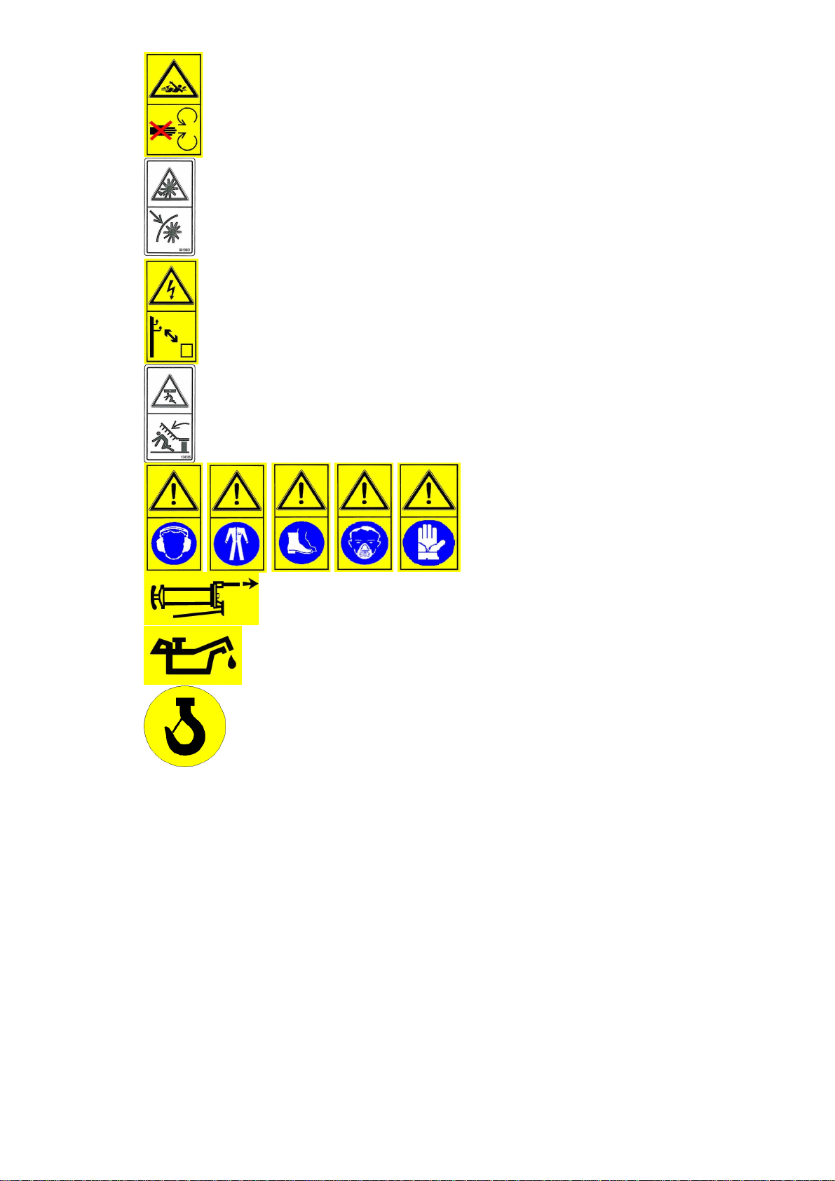
4.1.6 HIGH PRESSURE FILTER ( ONLY TRAILED MODELS)
The high pressure filter consists of a PVC body
(Det. 1.4) with two inputs and two outputs (item
8) (38 ".1/2").It also has a drain valve (POS. 6).
Inside there is a filter cartridge (POS. 3) which
has the task of collect any impurities presented
inside the circuit.
The high pressure filter should be cleaned following
the procedures outlined in chapter: routine
maintenance. (See § 7.7)
4.1.7 AGITATORS
Agitators are Venturi tubes supplied by the
pump through a manual valve that must be
always opened to allow the
wave of product before, during and after
treatment. The agitators valve shall be closed
only during system washing with clean
wa
t
er
f
rom
holding tank maintenance
23
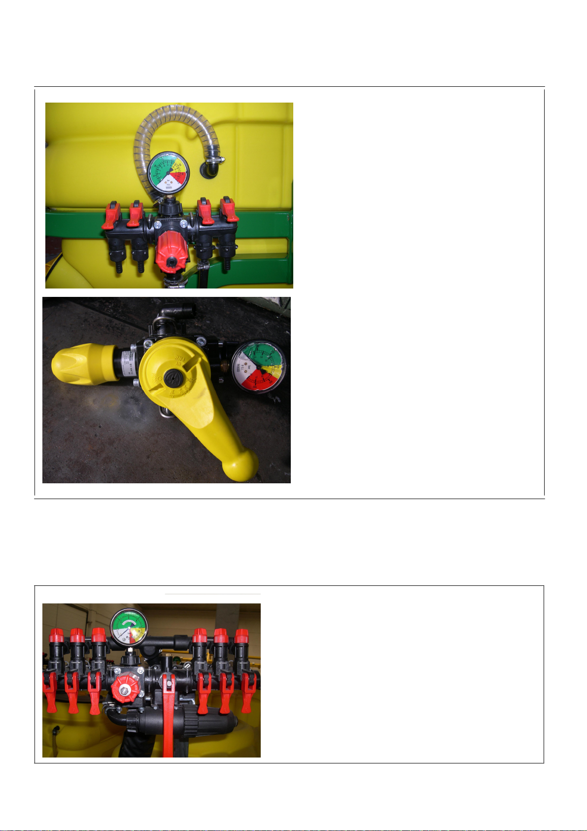
4.1.8 CONTROL UNIT
The control unit consists of a pressure
regulator (R), and a distributor (D).
At the pressure regulator is installed a
manometer (M) which allows to view the
pressure within the circuit. Using the
regulator it is possible to adjust (depending
on the number, the type of nozzles,
processing speed and other parameters), on
pressure operation of the machine .
In case of anomalies in the circuit, which
can generate strong pressure safety, it
intervenes a safety valve calibrated
according to models.
Pressure regulators may be manual
(mounted on the atomizer fig 1, or
tractors (model BYMATIC fig 2) or
electric (with control panel placed in the
cabin), in the latter case it is provided a
distance gauge fitted with a separator
because for security reasons it's not
possible to bring liquids in pressure in
the signal box. If the tractor is equipped
with a sealed cabin it is compulsory to
use electric controls.
Also for this device is attached related
manual.
4.1.9 DISTRIBUTORS
The Distributor (D) consists of gate valves or
cocks which convey the fluid in various directions.
M
D
R
FIG 1
R
D
M
This manual suits for next models
67
Table of contents


