Ecofreen MiSTER-T2 pro User manual


2
- Operator
’
s Manual
Safety Instructions
For Use By Qualified Personnel Only
When using your machine, basic precautions should always be followed, including the following:
Read all instructions. Use the Mister T2 Pro only for its intended use.
Mister-T2 Pro has to be operated with a precoating liquid for fabrics for DTG printer.
Cleaning MUST be done with distilled water only!
Other liquids alcohol or solvent may damage pumps or other components of the machine.
Damages caused by unauthorized liquids are excluded from the warranty.
Mister-T2 Pro comes with 12 months warranty.
This warranty includes the whole construction of the machine, mechanical parts, electronics, drawer
with rails, casing, pumps, electronic valve, and pipes.
Consumption items such as stainless-steel nozzles, seals, and filters are excluded from the warranty.
The set-up and installation of the machine has to be done under supervision of an authorized person.
The installation has to be done by 2 or more persons following the instructions of this manual.
Caution : The Plug has to be pulled out of the power outlet while maintenance.
La spina deve essere estratta dalla presa di corrente durante la manutenzione.
Never pull cord to disconnect the power, grasp plug and pull to disconnect from power outlet.
Protect the power cord by keeping it away from hot surfaces. Do not allow objects to sit on top of
the cord. This could cause damage to the cord and could become a fire hazard risk.
Caution : Do not operate machine with a damaged cord or if the equipment has been damaged.
Do not
disassemble or
attempt to
repair the machine
to
prevent risks
to
injury.
N'utilisez pas la machine avec un cordon endommagé ou si l'équipement a été endommagé.
Ne démontez pas et n'essayez pas de réparer la machine pour éviter les risques de blessures.
Call or take it to a qualified service person for examination and repair.
Incorrect assembly or repair could increase the risk of fire, electric shock, or injury to persons
when the equipment is used.
Supervision is necessary for any machine being used by or near children. Do not leave equipment
unattended while connected.
Care should be taken to arrange the cord so that it cannot be pulled or tripped over.
To reduce the likelihood of circuit overload, do not operate other high voltage equipment on the
same circuit.
The machine should only be used by trained personal after reading and understanding of the manual.

- Operator
’
s Manual 3
Table of Contents
Congratulations on your purchase of a pretreat Machine!
To work professionally with the machine and start production, please make sure you readthis
manual carefully.
Reproduction of this manual requires written consent.
Errors and amendments of technical details excepted; all rights reserved.
We are not liable for any direct or indirect damages caused by the use of this product.
Table of Contents
Machine Parts Diagram
............................ 4
Specifications
........................................... 5
Installation
.........................................................
6
Ventilation & Scanner (option)
.......................
9
Barcode Scanning Worksheet
.......................
10
Operating Instructions
Control Panel
Operation
........................................ 12
........................................ 13
Pretreatment Guide
Switching the Pretreat Liquid
.......................
14
Pretreating a Shirt
......................................
15
DTG Fixation Guide
........................................
16
Volume Chart
...................................................
17
Maintenance
Other Settings
(Important) .......................18
Angles of Nozzles
............................................
23
Preset
........................................................
25
Cost of Pretreat Liquid
...................................
27
Setting Mode for Other Setting
.......................
28
Trouble Shooting
...............................................
29
Warranty Information
............................ 30

4
- Operator
’
s Manual
Machine Parts Diagram
< FRONT >
Control Panel
LED Lamp
Capping Station
Two Nozzles
Platen (
16”x20”
)
Intake Vents
< BACK >
Ventilation Fan
Main Power
Switch
Scanner Connector
Emergency
Button
Multi-Inlet Selector Valves
Ventilation
(Ring Blower is
required separately)
Drain Connector
Intake Vents
Foot Switch

- Operator
’
s Manual 5
Number of Spray Nozzle Two Nozzles
Power Consumption 60W
Specifications
Dimensions 640mm(W) x 900mm(L) x 530mm(H)
Platen Size 40cm x 50cm (16" x 20")
Maximum Spray Area 40cm x 50cm (16" x 20")
Power Supply
Free Voltage (100V~240V 50/60hz)
Packing Size
670mm(W) x 935mm(L) x 840mm(H)
Liquid Consumption With Minimum Speed : about 85ml
With Maximum Speed : about 12ml
Circuit Diagram
Packing Weight 46Kgs
Spray Cycle Time 3 sec ~ 12 sec
Weight 36kgs

6
- Operator
’
s Manual
①
Drain Tube
②
Manual
③
Filter(4ea)
⑥
Power Cord
④
Cable Tie(4ea)
⑦
Waste Tank
⑤
Spanner
Installation
Gently open the top of the machine and find the accessory box inside of the machine and
please check if all the components are in the box.
1)
Machine Leveling
Please ensure the machine is properly placed and leveled. Otherwise, waste liquid
in the machine can leak.
To level the machine, turn the machine feet clockwise to decrease height and
counterclockwise to increase height.
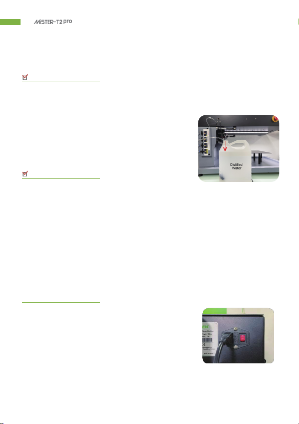
2)
Connect the Power Cord
The power switch and the power connection are located at the back of the machine.

- Operator
’
s Manual 7
Please make sure the nozzles alignment as the
picture on the right.
Installation
3)
Connect Drain Tube & the Waste Tank
The drain connector is located at the back
of the machine.
Connect the large tube (drain tube) to the connector
on the bottom and then place the other end in
a waste tank.
This will collect any excess pretreatment when the
machine run.
4)
Prepare a bottle with Pretreat Solution
If using ECOFREEN UNIVERSAL concentrate, mix the liquid and purified water as below.
Universal Water
1L + 2L = 3L for DARK or Blended
Universal Water
1L + 1L =2L for POLY
5)
Nozzle Alignment
Do NOT make the two nozzles horizontal as the picture
on the right.
Otherwise, sprayed pretreat liquid will be overlapped
in the middle of the T-shirts.
8
- Operator
’
s Manual
Installation
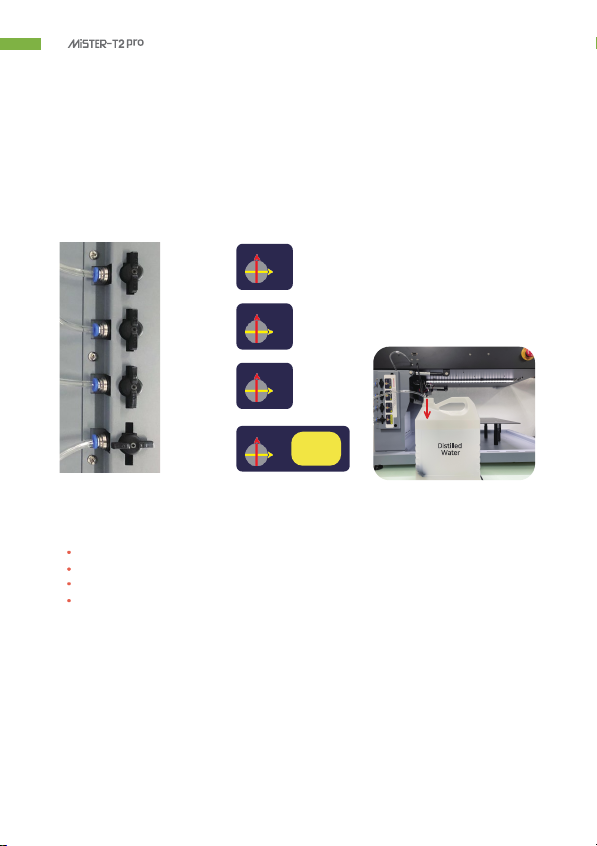
6)
Put the Filters into The Bottles
Please put the filters into the bottles for pretreat liquid or water and turn the valve clockwise
to open the preferred valve to spray the liquid or water.
Liquid
①
Liquid
②
Liquid
③
DISTILLED
WATER
* IMPORTANT
The water bottle should be placed in the 4th valve as the picture above.
Only one valve can be open at a time.
Flush with distilled water after daily use.
Inlet Filter must stay submerged at all times.
CLOSE
This position is
ONLY for
OPEN
DISTILLE D
WATER
CLOSE
OPEN
CLOSE
OPEN
CLOSE
OPEN

- Operator
’
s Manual 9
Installation
7)
Ventilation (Option)
Ring blower, vent hose & clamps are required separately as below.
*Required Ring blower spec*
diameter 4
”,
over 170CFM
Ring blower + Filter(option) + Vent Hose & Clamps
8)
Scanner (Option)
Enable barcode scanning and auto-start mode.
**The plug of scanner is left side on the machine.
Barcode scanner must with RS232 cable (9 hole female socket) as picture below.
RS232 Female Socket
(9 Hole)
RS232 Male Plug
(9 pin)
10
- Operator
’
s Manual
x x x x x x x x x x x x
Barcode Scanning Worksheet
1)
Please go to the web site - https://wepplication.github.io/tools/barcodeGen/
2)
Refer to the worksheet below and create the barcode (Barcode Type : UPC)
Continuous Spraying
1
~
9
* EX) 1 or 2 or 3: 10 or 20 or 30 shirts auto spraying
Auto Start
0
No Auto Start
:
Manual Start Button or Foot Switch Required
1
Auto Start after 1 sec.
2
Auto Start after 2sec.
3
Auto Start after 3sec.
~
9 Auto Start after 9 sec.
2nd Spray Location
1
1
~ ~
0 0
Start End *EX) 10 : from 1st cell to 10th cell
2nd Spray Section
0
No Spraying
1
Left Column Only
2
Right Column Only
3
Both Left & Right Column Spraying
1st Spray Location
1
1
~ ~
0
0
Start End * EX) 36
:
from 3rd cell to 6th cell
1st Spray Section
0
No Spraying
1
Left Column Only
2
Right Column Only
3
Both Left & Right Column Spraying
Round Trip
0
Uni Direction Spraying
1
Bi Direction Spraying
Spraying Volume
1
0
~ ~
9
9
Described in the next page...

- Operator
’
s Manual 11
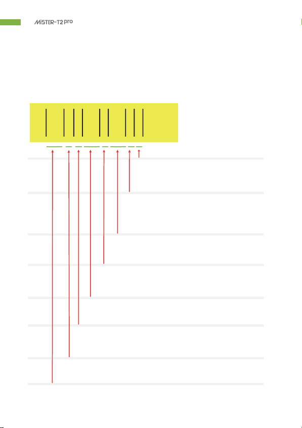
Barcode Scanning Worksheet
1st
2nd
Barcode
Volume,
Direction
Spray
Section
Spray
Location
Spray
Section
Spray
Location
Auto
Start
Continuous
Spraying
10ml
Uni
direction
Both
Left & Right
1~0
All
N/A
N/A
off
off
15ml
Bi
direction
Left
Only
2~9
cell
N/A
N/A
off
off
15ml
Bi
direction
Right
Only
2~9
cell
N/A
N/A
off
off
10ml
Both 1~3 Both
6~9
off
off
Bi
Left & Right cell Left & Right
cell
direction
* Please refer to the setting below
Cell
1st
2
3
4
5
6
7
2nd
8
9
0
10ml
Bi
direction
Both
Left & Right
1~0
All
N/A
N/A
2s
Interval
10
Shirts
*
While auto start, open top lid = pause / press stop = reset
12
- Operator
’
s Manual
⑩
⑪
⑫
⑬
⑭ ⑮
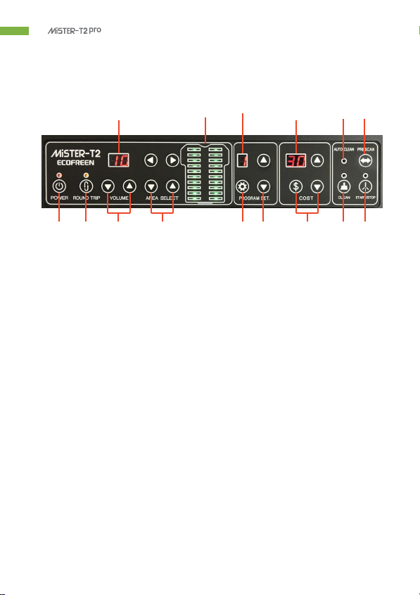
Operation Instructions
Control Panel
①②
③
④⑤
⑥
⑦⑧⑨
Understanding the Control Panel Menu
1)
POWER ON/OFF BUTTON
2)
ROUND TRIP BUTTON
:
Spray pretreat liquid with bi-direction when the light above is on.
Otherwise, it sprays with uni-direction only.
3)
VOLUME BUTTON : Freely adjustable the volume of liquid (about 12~85ml ).
4)
AREA SELECT BUTTON
:
Freely adjustable the spray area. (Please refer to the page 13 for the
example of setting the spraying area.)
5)
PROGRAM SETTING BUTTON : Setting for preset options.
(Please refer to the page 25 for how to set the options above)
6)
PRESET OPTION SELECT BUTTON
:
9 options can be saved and retrieved. (from 1 to 9 options)
7)
COST SETTING BUTTON : Setting the cost of pretreat liquid for each spraying.
(Please refer to the page 27 for setting the cost of liquid)
Also, for setting the unit for ink & currency, period & time for
auto cleaning system.
(Please refer to the page 28 for how to set the options above)
8)
NOZZLE CLEANING BUTTON
9)
START / STOP BUTTON : Spray or stop the pretreat liquid.
10)
DISPLAY for SPRAYING VOLUME (10~99).
11)
DISPLAY for SPRAYING AREA.
12)
DISPLAY for PRESET OPTIONS (option # from 1 to 9).
13)
DISPLAY for COST of LIQUID for EACH SPRAYING.
14)
AUTO CLEAN LAMP
:
Automatic spray for 2 seconds in every 4 hours when power is off.
(Please refer to the page 28 to program the time for the cycle.)
(The main power switch on the back of the machine must be turned on
for the automatic cleaning system.)
15)
PRESCAN BUTTON : Preview the spraying area by laser.
- Operator
’
s Manual 13
Operation by Auto Start Mode
Operation by Setting Each Options
Operation Instructions
Operation
1)
Turn on the POWER SWITCH on the back of the machine.
*
Ensure the emergency button on the left
side of the machine is not locked.
If the emergency button is locked,
unlock by turning the button clockwise.
2)
Press the POWER BUTTON on the control panel to start the machine (Press and hold for a few seconds)
*
There are 3 ways to operate the machine as below*
Operation by Retrieving the Preset
Press or
buttons to retrieve the preset options
which are already saved. (Please refer to the page 25 to program
preset options)
Scan the barcode for auto start mode. Refer to the page 10 to create the barcode.
(Scanner is optional). * While auto start, open top lid = pause / press stop = reset
3)
SELECT SPRAYING DIRECTION : Press ROUND TRIP BUTTON to control whether the machine does
unidirectional spray or bidirectional. When the round-trip light is on,
the machine will spray bidirectional. If the light is off, the machine
will spray unidirectional.
4)
SELECT SPRAYING VOLUME : Choose from 10 to 99.
*
Please refer to the volume chart on page 17.
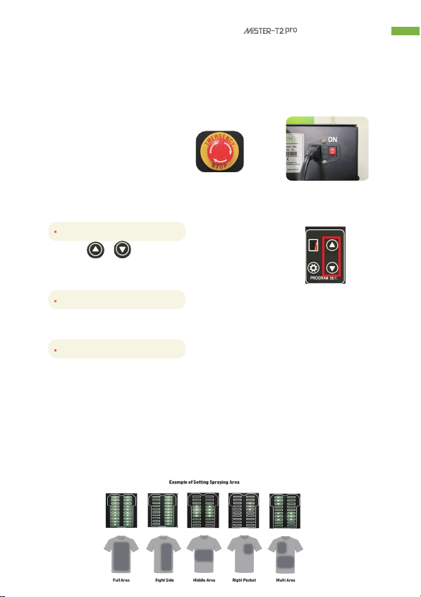
5)
SELECT SPRAYING AREA : Change the area
Spray area is divided into 10 sections and only sprays on the selected area.
The area can be freely adjustable as below.

14
- Operator
’
s Manual
Operating Instructions
Operation
(continued)
6)
BOTTLE SELECT
Switch the bottles by turning the desired valve in clockwise.
*
Only ONE valve can be open at a time.
Closed Open
7)
CLEANING
When you change the bottle to another (to different liquid), please press “CLEAN” BUTTON.
Please clean the tubes and nozzles with water in valve #4 in order to flush the tubes of the previous
liquids before switching to another liquid.
This will prevent any clogs that may occur due to chemical reactions.
WARNING
IF YOU USE MULTIPLE COATING LIQUIDS, CHEMICAL REACTION MAY OCCUR WHICH CAN BE
THE REASON FOR THE NOZZLES TO BE CLOGGED
Si vous utilisez plusieurs liquides de revêtement, une réaction chimique peut se produire,
ce qui peut être la raison pour laquelle les buses sont obstruées
8)
START / STOP
Press the START BUTTON to start spraying your shirts with pretreat.
Also press button again to STOP if needed.
Switching Pretreat Solutions
a.) When switching between pretreat solutions, close the valve by turning the valve in counterclockwise
and open the 4th valve which should be filled with water for cleaning.
b.) Press the “CLEAN” button. Let the machine spray until you see no pretreat solution in the tube
(7~10 secs).
c.) Close the 4th valve (distilled water) and open the preferred valve.
Press “CLEAN” button to flush out the water (7~10 secs).
Once you see the tubes filled with pretreat solution, press “CLEAN” button again to stop
spraying/flushing.

- Operator
’
s Manual 15
Pretreatment Guide
Pretreating a shirt
Use the Recommended Spray Volume and Fixation Temperature.
1.
Please prepare all equipment to be turned on. Turn on the machine.
2.
If pretreatment is already loaded in the tubes, skip steps 2 & 3.
Press the clean button to ensure that the pretreatment solution is loaded into the tubes.
This usually takes about 7~10 seconds.
3.
Once you see the machine spraying the pretreat solution, press clean button again to stop the spraying.
4.
It is recommended to prepress your shirts on a heat press for 5 seconds to get rid of any wrinkles
before spraying. Load your shirt.
Tuck the sides of the shirts in the platen to avoid getting it caught in the railings.
5.
Ensure you have set the appropriate volume and spray direction settings.
The spray setting guide can be found on Page 16 & 17 of this manual.
Press the start/stop button to start spraying once you have your shirts and settings set.
(There are 3 ways to operate the machine. Please refer to the page 13)
6.
Place the pretreated shirts on the heat press to dry. Place a heat-resistant release sheet,
such as Teflon/Silicon sheet between T-shirt and the heat press.
* Use the following settings to dry the shirt.
The below settings are to be used as a guide. Some adjustment may be necessary.
DARK COTTON : 320F ~340F (160C ~170C), 60~70 sec.
BRIGHT COTTON : 293F ~320F (145C ~160C), 35~45 sec.
POLY
:
320F ~340F (160C ~170C), 90 sec.
If the shirt is not dry after the recommended time, repress the shirt until dry.
* Pretreatment Note
Different brands and types of shirts will require different amounts.
Start with the recommended amounts on page 17 and adjust accordingly.
Some testing may be required for new styles and brands of shirts.
It is recommended to keep a record of how much is required for each brand/type of shirt.

16
- Operator
’
s Manual
Pretreatment Guide
DTG Pretreatment & Fixation Guidance
Heat Press Setting for Pretreatment
0
Garment Bright Cotton Dark Cotton Poly Blended (Hoodie)
Quantity 10-20g 20-35g 30g 50g
Volume Level on
Mister-T2 Pro
Volume Level
10~30
Volume Level
10~20
Volume Level
20
Volume Level
50
Spraying Direction
on Mister-2 Pro
Uni-Direction Bi-Direction Bi-Direction Bi-Direction
Time 35-45 seconds 60-70 seconds 90 seconds 90-120 seconds
Temperature 293-320℉ (145-160℃) 320-338℉ (160-170℃) 320℉ (160℃) 320-338℉ (160-170℃)
Pressure 1.0-2.0 Bars 14-29 PSI 7.0-8.0 Bars 101-116 PSI 7.0-8.0 Bars 101-116 PSI 7.0-8.0 Bars 101-116 PSI
Ink Heat Press Curing Setting
Time
45-55 seconds 90-100 seconds 90 seconds 90-120 seconds
Temperature
293-320℉ (145-160℃)
320-338℉ (160-170℃)
320℉ (160℃)
320-338℉ (160-170℃)
Pressure
0-1.0 Bars 0-14 PSI
0-1.0 Bars 0-14 PSI
0-1.0 Bars 0-14 PSI
0-1.0 Bars 0-14 PSI
Note) The above conditions subject to change depending on the fabric type.
Please start with the recommended amounts he liquid above and adjust accordingly.
*
Dilution Guide for T-PRT-UNIVERSAL
Universal Water
1L +
2L
= 3L for DARK or Blended
Universal Water
1L +
1L
=2L for POLY

- Operator
’
s Manual 17
Pretreatment Guide
Volume Chart
The above are general guidelines on the speed and setting to use the pretreat your shirts.
Please note that some adjustments may be needed depending on the pretreat solution you use.
If shirts are not dry using the recommended heat press settings, please repress the shirt
until it is completely dry before printing.
Not all shirts will be the same, so we highly recommend you do testing on any new shirts you pretreat
before going into commercial production.
* The volume of the pretreat liquid showed on the display is provided for general information
purposes only.
It does not represent the accurate volume of the liquid.
ECOFREEN will have no responsibility for the accuracy of the data and the issue which may arise
from using or relying on the information.
* VOLUME CHART
18
- Operator
’
s Manual
DAILY MAINTENANCE
MONTHLY MAINTENANCE
Maintenance
Press “CLEAN” button to flush with water and clean the nozzle
everyday at the end of work.
Never leave the filter exposed to air to prevent filter from
drying and clogging.
Always put the filter into the pretreat or cleaning water container.
Please replace the filter every two months.
Otherwise, filter will get clogged and unable to suck enough liquid, which causing inconsistent spraying.
[ IMPORTANT NOTE ]
Running the machine without filter will cause the damage of pump, solenoid valve,
nozzle and inconsistent spraying.
The warranty will be void if the machine runs without placing the filter.
Please replace the sponge in capping station every two months.
Otherwise, dried liquid on the sponge will cause the damage of nozzle and make it clogged.
** IMPORTANT
Try to keep the main power switch on.
This will enable automatic cleaning program which is purging
for seconds by every 4 hours when not in use.
ON

- Operator
’
s Manual 19
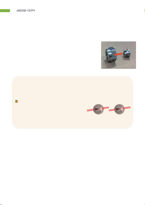
Nozzle Tip Nozzle
Cap Nut
Maintenance
Cleaning The Nozzle
Step 1
:
Press POWER ON/OFF BUTTON on the control panel to switch off.
Step 2 : Gently open top lid.
Step 3
:
Turn the Nozzle Cap Nut to counterclockwise
to loosen and dislocate the nozzle.
Step 4 : Clean the Nozzle Tip, Cap Nut and Sol Valve using water and wet paper tower.
** Reference
The nozzles can be cleaned in an ultrasonic cleaner.
To clean the nozzle and its parts, please fill distilled water
and run it for 6~7 mins.
** Storage
NEVER LEAVE THE NOZZLES EXPOSED TO AIR.
Remaining precoat can be dried out and stick to nozzle.
This will cause inconsistent spraying or clogging of the nozzle.
20
- Operator
’
s Manual
When assembling Nozzle Tip after disconnecting and cleaning the nozzle,
Pl
ease
mak
e
sur
e
the
Nozzl
e
Tip
’
s
alignment.
Failure to do this will result in the pretreat not being sprayed properly on the shirt.
CAUTION
Please make sure the nozzles alignment as the
picture on the right.
S'il vous plaît assurez-vous que l'alignement des buses comme l'image sur la droite
Maintenance
Cleaning The Nozzle
(continued)
Step 5
:
Assemble the Nozzle Tip and the Nozzle Cap Nut as the picture
on the right.
Filter Maintenance
NEVER LEAVE THE FILTER EXPOSED TO AIR.
(NE JAMAIS LAISSER LE FILTRE EXPOSÉ À L'AIR.)
Doing so will cause the filter to be clogged.
The filter is a consumable part and will need to be replaced every two months.
If your machine is not spraying liquid, check to see if the filter is clogged.
Simply removed the filter from the end of the inlet tube and start spraying.
If spraying occurs after the filter is removed, then we can conclude filter is clogged and
will need to be replaced.
Other manuals for MiSTER-T2 pro
1
Table of contents
Other Ecofreen Paint Sprayer manuals


