manuals.online logo
Brands
  1. Home
  2. •
  3. Brands
  4. •
  5. BARKER & WILLIAMSON
  6. •
  7. Antenna
  8. •
  9. BARKER & WILLIAMSON AT-110 User manual

BARKER & WILLIAMSON AT-110 User manual

The Barker & Willamson Model AT-110 is a short dipole for the 80, 40, 20, 15 and 10 meter amateur ands. The 80 and
40 meter ands have a seperate trap (40 meters) which will give maximum efficiency and still e a short antenna for small
lots and limited space. On 80 meters, the 40 meter traps work as loading coils, keeping the antenna short. The AT-110
will also provide operation on 20, 15 and 10 meters ecause of the harmonic relationships to 80 and 40 meters. All short
dipole antennas will have a andwidth narrower than a full size half wave dipole. Therefor, an antenna tuner may e
helpful.
The AT-110 is est installed as an inverted Vee. Satisfactory results may e o tained with the center as low as 20 feet,
however 30 feet or more is recommended. If a flat top installation is desired, it is est to have the center supported due
to the weight of the traps/loading coils and coaxial feed line.
INSTALLATION INSTRUCTIONS
WARNING
Outdoor antennas and lead-in conductors from antenna to uilding shall not cross over electric light or power circuits
and shall e kept well away from all such circuits so as to avoid the possi ility of accidental contact. Where proximity
to electric light or power service conductors of less than 250 volts cannot e avoided, the installation shall e such so
as to provide a clearance of at least 2 feet. Where practical, antenna conductors shall e installed so as to not cross
under electric light or power conductors.
(1) Please read through all the instructions efore starting. It is imperative to follow the instructions step y step, in
the order shown, to achieve satisfactory results with your antenna.
(2) Remem er that throughout the assem ly procedure, wire lengths are always to e symmetrical on oth sides of the
antenna. Your traps may or may not have a color dot on one end of them. You may ignore these color dots. They do not
have to match each side.
(3) Cut the wire segments. The wires must e cut approximately 2 - 3 feet longer than the dimensions shown in figure
1. This is to leave room for the hookups and tuning adjustments. Here are the lengths that you should cut (including the
2 - 3 ft extra). Cut two wires 36', and two wires 25' 6". Remem er, you can always trim the wire shorter after tuning, ut
once cut too short . . .
(4) Attach one end of the wire segments in the permanent manner shown in figure 2, working out from the center conductor.
Allow roughly 6 to 8" of wire through the eye olt efore starting your wrap. Attach the 36' segments to oth sides of the
center connector. Attach the 25' 6" segments to one side of the TR40A traps.
(5) Now assem le the sections of the antenna together paying attention to figures 1 and 3. The wire segment lengths shown
are your starting point for tuning the antenna. Make sure that you make temporary connections as shown in figure 3. This
will leave each wire segment with one end permanently soldered, and the other end temporarily connected for adjustment.
(6) Raise your antenna, and check the VSWR on 40 meters. If the resonant frequency is low, shorten the 33' segments.
If it is high, lengthen the wires. After the desired frequency is achieved, make permanent attachment for these segments
as shown in figure 2, trimming off excess wire.
(7) Finally, adjust the 22' 6" segments at the insulators for 80 meters.
BARKER & WILLIAMSON
603 CIDCO ROAD
COCOA, FL 32926
321-639-1510
12/00
MODEL AT-110 ANTENNA
80, 0, 20, 15 and 10 Meter Bands
Power Rating: 1000W PEP, 500W Output
Length: 110 Feet
Figure 1: Theoretical wire lengths and trap arrangement.
Figure 3: Temporary hookup
for tuning. Loosely twist and
tape ends in.
Figure 2: Permanent hookup. After passing
through the ey olt, wrap the wire around itself
5 times efore soldering to the terminal.
WARRANTY STATEMENT
Barker & Williamson guarantees each product to e free from defects in material and workmanship for 90 days from date of
purchase. The warranty applies to the original purchaser only, and we will repair or replace the product at our discretion. Under
no circumstances will Barker & Williamson e lia le for any damages or consequential damages arising from use or misuse of
our products. Warranty is voided if product is su ject to misuse, neglect, accident, improperly installed or used in violation of
the instructions furnished y us. We reserve the right to make changes in design at any time without o ligation to update
previously manufactured models. This warranty is given in lieu of any other warranty, expressed or implied.
Figure 4: Typical SWR curves with antenna installed as an inverted
Vee, with center 30 feet high and ends 10 feet a ove ground.

Other BARKER & WILLIAMSON Antenna manuals

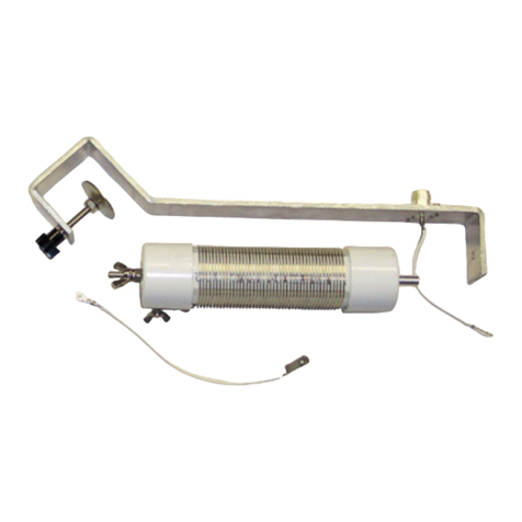
BARKER & WILLIAMSON AP-10B User manual

BARKER & WILLIAMSON

BARKER & WILLIAMSON AP-10B User manual

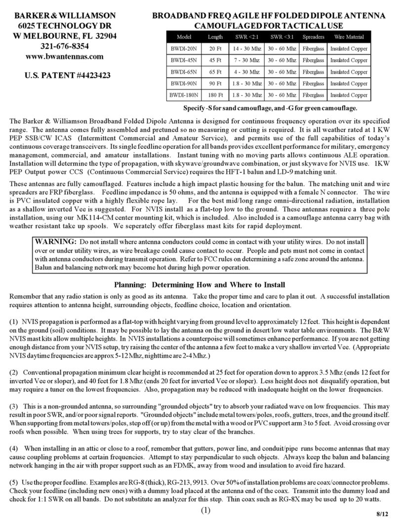
BARKER & WILLIAMSON BWDI-20N User manual

BARKER & WILLIAMSON

BARKER & WILLIAMSON BWDI-20N User manual

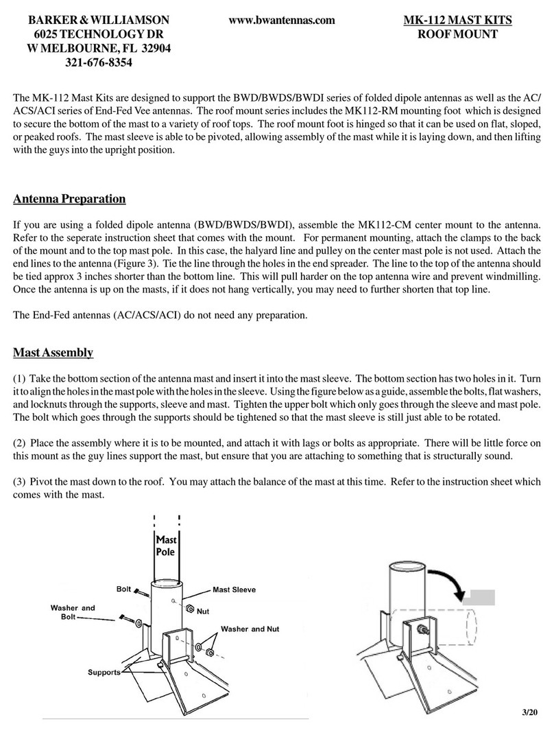
BARKER & WILLIAMSON MK-112 MAST KIT User manual

BARKER & WILLIAMSON

BARKER & WILLIAMSON MK-112 MAST KIT User manual

Popular Antenna manuals by other brands

Intellian v150NX Installation & Operation User Guide

Intellian

Intellian v150NX Installation & Operation User Guide

Ubiquiti PrismAP-5-45 quick start guide

Ubiquiti

Ubiquiti PrismAP-5-45 quick start guide

AMX 5dBi omnidirectional antenna NXA-WAP2405A Specifications

AMX

AMX 5dBi omnidirectional antenna NXA-WAP2405A Specifications

Simrad GS70 installation guide

Simrad

Simrad GS70 installation guide

Strong SlimSat SA61 user manual

Strong

Strong SlimSat SA61 user manual

TracVision TracVision M3 installation guide

TracVision

TracVision TracVision M3 installation guide

SLX 27884D4 user guide

SLX

SLX 27884D4 user guide

Diamond Antenna CPVU8 Operation instructions

Diamond Antenna

Diamond Antenna CPVU8 Operation instructions

Lancom AirLancer ON-T360ag Mounting instructions

Lancom

Lancom AirLancer ON-T360ag Mounting instructions

M2 Antenna Systems 235-11 Assembly manual

M2 Antenna Systems

M2 Antenna Systems 235-11 Assembly manual

Intellian i2 Installation and operation manual

Intellian

Intellian i2 Installation and operation manual

Diamond Antenna CR8900A instruction sheet

Diamond Antenna

Diamond Antenna CR8900A instruction sheet

Antenna Experts LP-500-2500 installation manual

Antenna Experts

Antenna Experts LP-500-2500 installation manual

Shure PSM PA821SWB user guide

Shure

Shure PSM PA821SWB user guide

Goobay DVB-T DIA 220 PS Mini black Assembly instructions

Goobay

Goobay DVB-T DIA 220 PS Mini black Assembly instructions

KVH Industries TracVision R6 DX quick start guide

KVH Industries

KVH Industries TracVision R6 DX quick start guide

Navman GPS 1240 installation manual

Navman

Navman GPS 1240 installation manual

Sirio Antenne SA 270 SN installation manual

Sirio Antenne

Sirio Antenne SA 270 SN installation manual

manuals.online logo
manuals.online logoBrands
  • About & Mission
  • Contact us
  • Privacy Policy
  • Terms and Conditions

Copyright 2025 Manuals.Online. All Rights Reserved.