BarlowTyrie 9111210 User manual
BARLOW TYRIE
quality since 1920
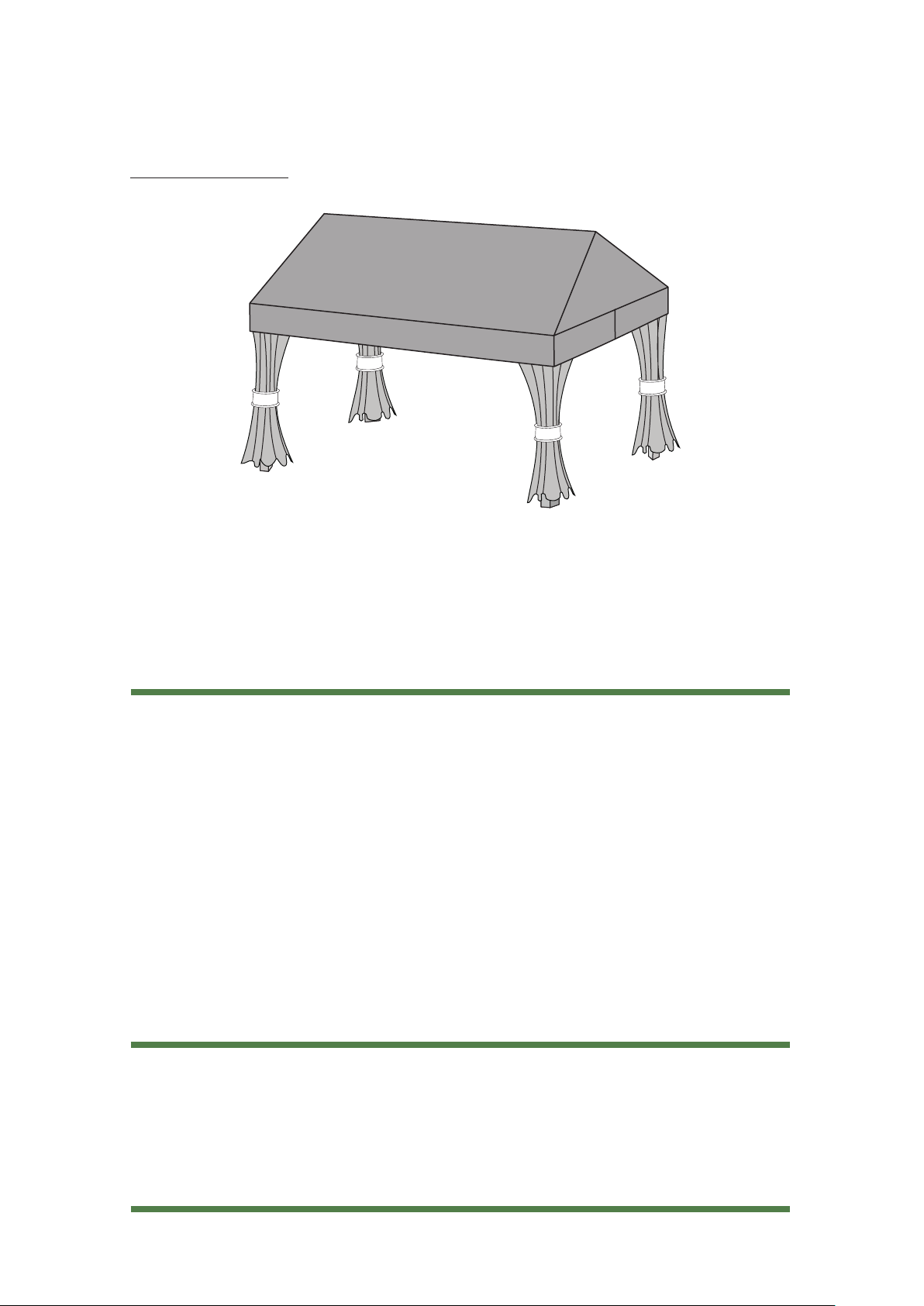
3.66 x 4.5m - 12’ x 15’ Pavilion Shelter with Double Rail Beams
Ref: 9011215
Step by Step Assembly Instructions
Pavilions
Before you begin
These installation instructions will lead you through the process of installing your new pavilion.
The installation of the pavilion requires special attention to certain detail. Before you begin you
should:
Check your order Make sure the contents of the carton match the product numbers on your
order. Contact your dealer if there are any damaged, missing or incorrect parts.
Pay attention to safety Because of the size and weight of certain parts, installation is
recommended with no fewer than two people. Always maintain a clean, organized work area.
Make sure you have the right tools and materials Barlow Tyrie supplies the appropriate
fasteners upon request through your dealer for anchoring the pavilion securely to the ground.
If you are unsure about the required anchoring system best suited for your pavilion consult your
dealer for the proper fastening method.
Review entire installation guide This step gives you the opportunity to contact your dealer to
answer any questions before you begin.
Assembly requirements
Two people Spirit level
Hand drill Screwdriver set
Step ladder Long nose pliers
Spanners Rubber hammer
Tape measure
www.teak.com Page 1 of 16
Step by Step Assembly Instructions
3.66 x 3m - 12’ x 10’ Pavilion with Cabrio Folding Roof
Product Ref: 9111210
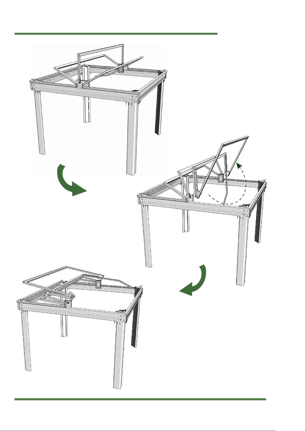
Assembly overview
BARLOW TYRIE
quality since 1920
www.teak.com Page 2 of 16
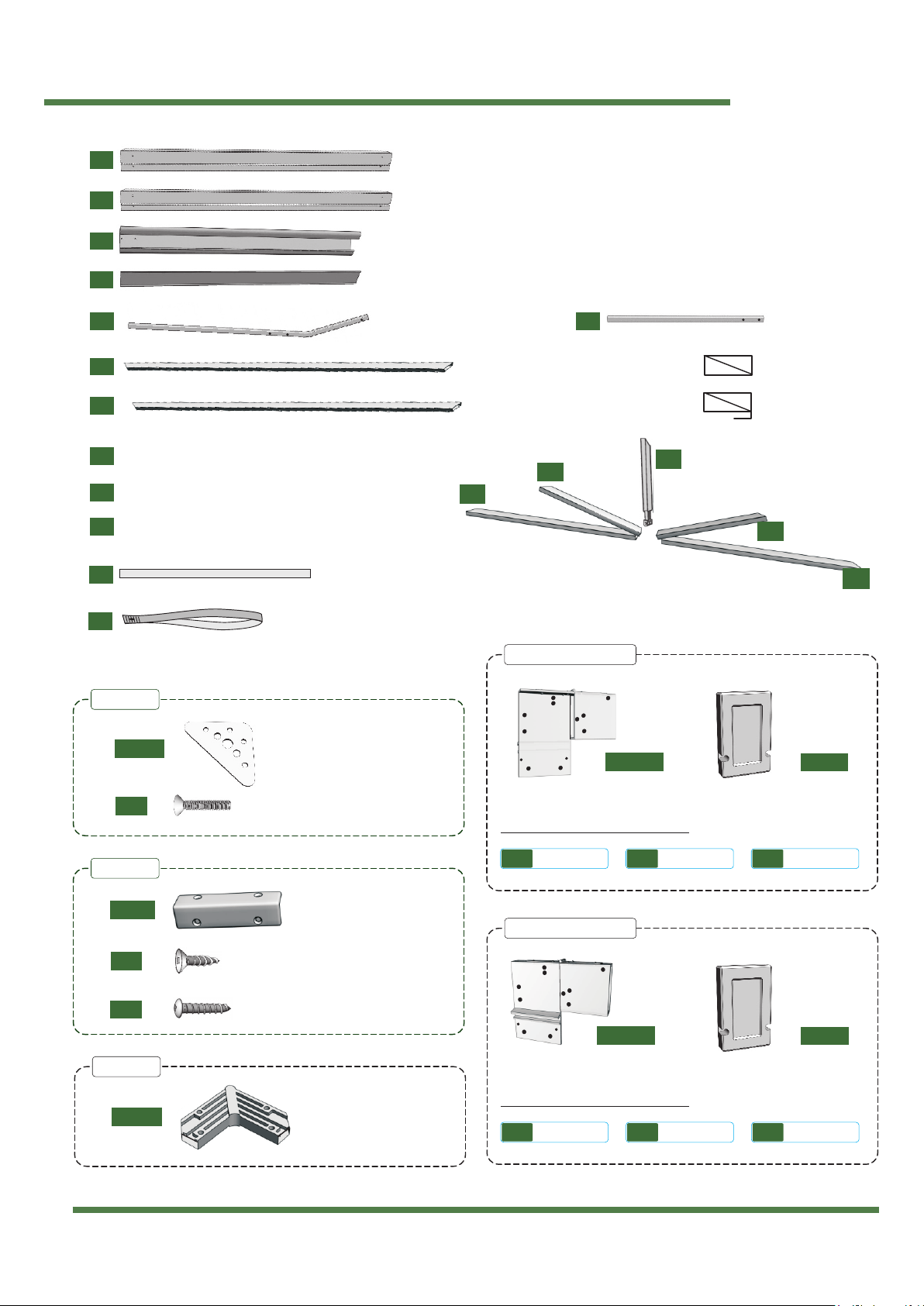
Part list
BARLOW TYRIE
quality since 1920
www.teak.com Page 3 of 16
2x B1
1x L1
3x T1
2x T2
4x T3
T3
T3
T4
T4
T5
4x T4
2x T5
4x R1
1x R2
2x B2
4x P1
4x P2
Lower Truss with 5/16” dia hole about pivot point
MiddleTruss with 5/16” dia hole about pivot point
Center Truss with plastic spring slide insert
Lever Arm Strap
Flat Bar Roof Trusses
1x
1x
1x
1x
1x
1x
Post End Plate
Inlcudes the following sub kits:
Inlcudes the following sub kits:
16x 002
4x AL005
Roof Hinge
Roof Hinge
1x KC.02L
1x KC.02R
1x PL005
1x PL005
Roof Hinge Cover
Roof Hinge Cover
Plastic Corner Bracket
4x K4.01
8x 025
16x 015
Plastic Corner Insert
10x PL007
KC.01
KC.04-A
KC.05
KC.03 (RHS KIT)
KC.02 (LHS KIT)
SKC.03-1 SKC.03-2 SKC.03-3
SKC.03-3SKC.03-2
SKC.03-1
Beam 3 mtrs 10 feet (roof hinge side)
Beam 3.66 mtrs 12 feet (transverse side)
Triangular Corner Post
Corner Post Cover
Full Length Lever Arm 1x L2 Dummy Lever Arm
Transverse Roof Support (no grove)
Transverse Roof Support (with grove)
Cross-Sectional View
Cross-Sectional View
Plate Screw 1/4” x 13/4”
Metal Screw #10 - 3/4”
Metal Screw #8 - 3/4”

Part list
BARLOW TYRIE
quality since 1920
www.teak.com Page 4 of 16
1/4” dia Nylon Bushing
Nylon Lock Nut - 1/4”-20
Plastic Finishing Hole Cap
Hinge Box Side Cover
Lever Arm Fork
Fork Installation Guide
Lever End
Cover
16x 002
4x PL014
2x PL01 1
1x PL012
2x PL010 2x PL013
4x PL016
4x PL07 4x PL015
1/4” Flat Washer
1x 002
2x 020
2x 018
1x 005
1x 010
2x 016
#8 Square Head Screwdriver Bit
#10 Square Head Screwdriver Bit
Pulleys included with curtains
PL101
20x R3 Velcro Strips
Carriage Bolt - 5/16” x 2”
5/16” Flat Washer
16x 003
16x 007
16x 012 5/16” Nylon Lock Nut
5/16” Nylon Lock Nut
Nylon Bushing - 5/16”
5/16” Flat Washer
5x 012
10x 006
5x 004
10x 019
2x
Tab Washer 1/4”-20
Roof Hinge Cover Screw #10-3/8”
1/4” Flat Washer
1/4” Lock Washer
Hex Bolt - 1/4”-20 x 5/8”
2x 008
2x 001
2x
2x 005
2x 014
2x 026
2x
Nylon Bushing - 5/16”
Carriage Bolt - 5/16”x 2”
5/16” Flat Washer
5/16” Lock Washer
5/16” Nut
2x 011
2x 009
2x 003
4x 006
2x 019
SKC.03-1
SKC.03-2
SKC.03-3
KC.07
KC.06
KIT - 08
MISC
Hex Bolt - 5/16” x 31/4”
Cover Screw - 1/4” x 13/4”
Strap Screw - 1/4” x 13/4”
Self-tapping Screw - #12 x 13/4”
BARLOW TYRIE
quality since 1920
www.teak.com Page 5 of 16
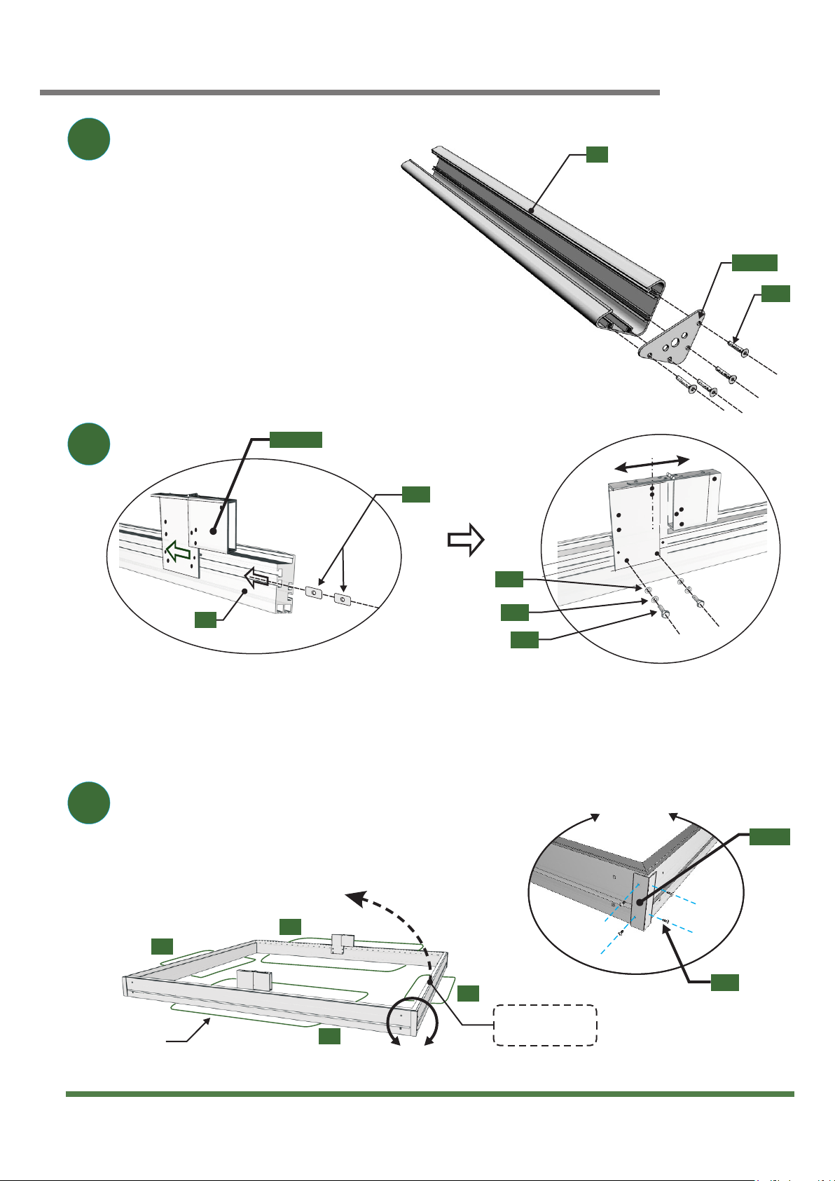
Getting started
3
2
1
P1
AL005
002
Roof will open
from this side
Cardboard
B1
B1
B1
B2
B2
KC.02L
A-A
001
005
014
008
View A-A
015
K4.01
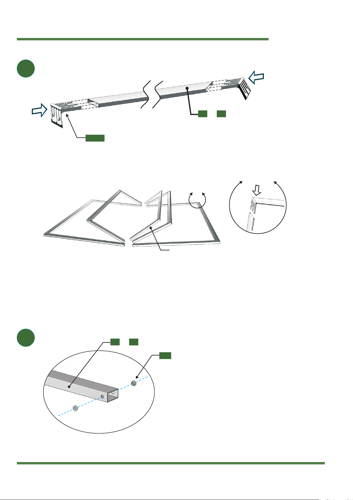
Secure the base plates (AL005)to the bottom of each
of the aluminium corner posts (P1)using metal bolts (002)
as shown in the diagram. (Repeat step for all four corner
posts.)
Install the two roof hinges on the beams (B1)by first inserting two tab nuts into the bottom interior groove of both
beams. Then slide the tab nuts till the mid section of the beams. Install the roof hinges on both beams using bolts
and washers shown in the above right hand side diagram. LIGHTLY TIGHTEN BOLTS. The hinge will be centered and
bolts will be tighten in step 6.
On a flat surface, assemble all the beams together by fixing the
aluminum corner bracket (K4.01)at each corner, using the metal
scews (015)supplied, as shown in the diagram. You may use
pieces of the cardboard box to protect the frame from scratches.
Assembling the roof
BARLOW TYRIE
quality since 1920
www.teak.com Page 6 of 16
5
4
T1 T2
&
T3 T4
&
Use a Rubber
Hammer
Nylon Bushing
Roof Truss Ends
View A-A
Use a Rubber
Hammer
MiddleTruss Assembly
A-A
PL007
019
Install the plastic corner inserts (PL007)at each end of the transverse
roof supports (T1)and (T2)as shown in the figure above.You will need a
rubber hammer to insert them properly
Complete the assembly by inserting the trusses (T3), (T4)and (T5)at each end of the
transverse roof supports as shown in the figure above. Again you will need a rubber
hammer to insert them properly.
On each end of the roof truss assemblies (T3)and (T4)
install two plastic bushings as shown in the diagram
BARLOW TYRIE
quality since 1920
www.teak.com Page 7 of 16
Assembling the roof framework
6
B-B
View C-CView B-B
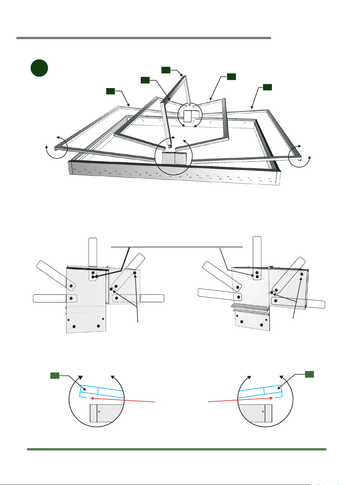
Install the middle plastic stub truss on The
upper hole can be used in time if more pressure needs to
be exerted by the middle truss onto the roof fabric.
the lower hole.
Lay the trusses on top of the beam assembly in the order and orientation shown by the
diagram above. Consult views B-B, C-C, D-D and E-E for specific detail. Then turn to the
next page for a description on how to fix each trusses to the hinges.
E-E
D-D
Transverse
Groove Should be
Facing Downwards
Support
T2
T2
T3
T3
T4
T5
T4
View D-D View E-E
C-C
Holes used for
Lever Arm
and Dummy
Lever Arm
(see Step 9)
Holes used for Lever Arm
and Dummy Lever Arm
(see Step 9)
Assembling the roof framwork
BARLOW TYRIE
quality since 1920
www.teak.com Page 8 of 16
F-F F-F
Transverse Support
Groove Facing
Downwards
Tighten Bolts
(repeat on other side)
Center Hinge Assembly
View B-B
(Hardware Installation)
View B-B
(TOP VIEW)
See Through
View
View F-F
004
006
002
006
KC.02L
014
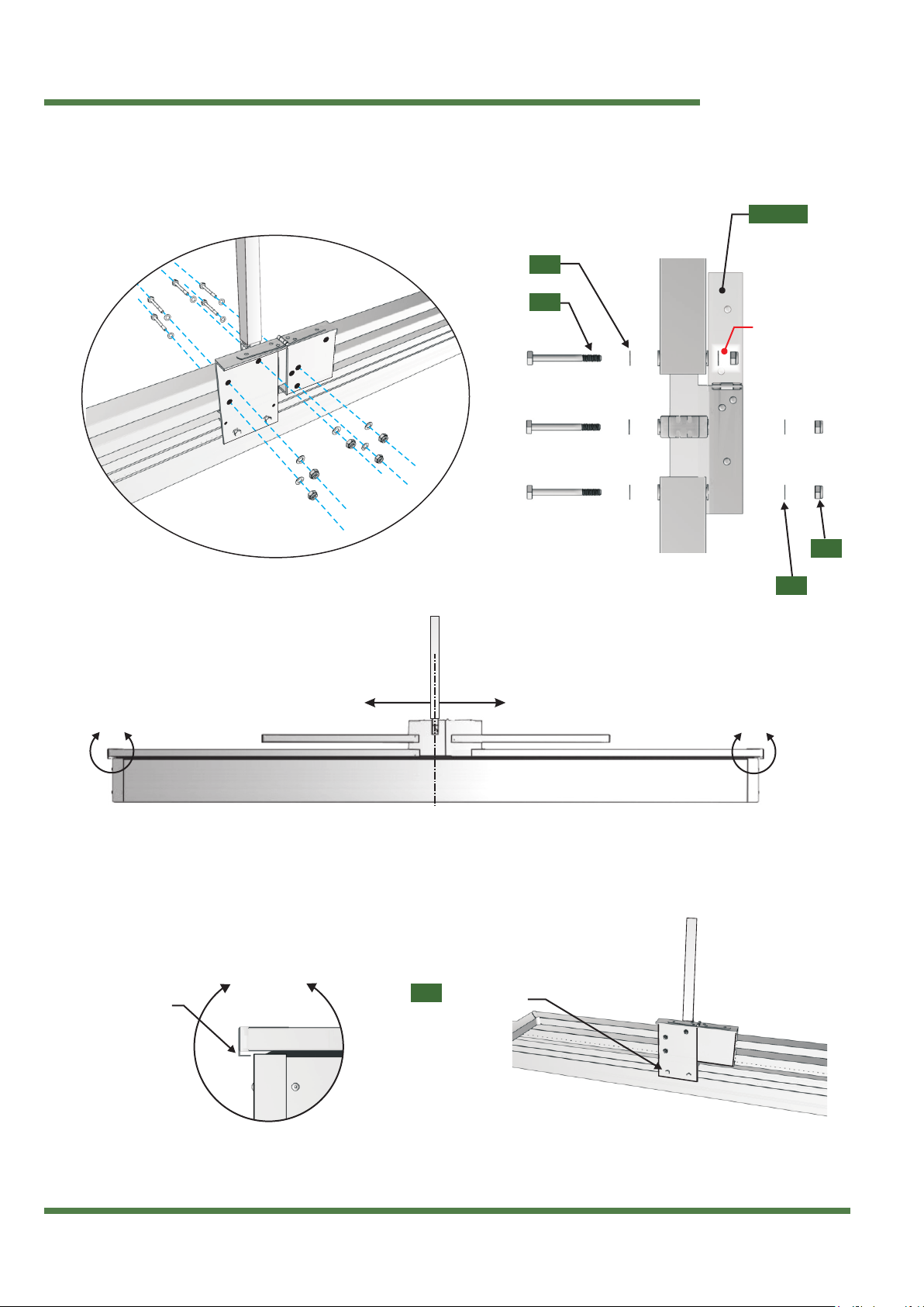
Install the trusses on the hinge using hardware shown in views B-B.
Notice that only one side is shown. Repeat this step on the other hinge.
Once the trusses have been fixed properly to each hinge, center the roof assembly
by allowing the protruding groove of (T2)to extend just beyond the edge of beam
(B2)(see view F-F). Then tighten the hinge bolts as shown in the bottom right diagram.
Installing the corner posts
BARLOW TYRIE
quality since 1920
www.teak.com Page 9 of 16
View G-G View G-G
(TOP VIEW)
Flat Washer
007
Lock-Nut
012
003
003
7
Top View
G-G
P1
P1
P2
P2
P2
Locking
Key
Assembly
KC-07
002
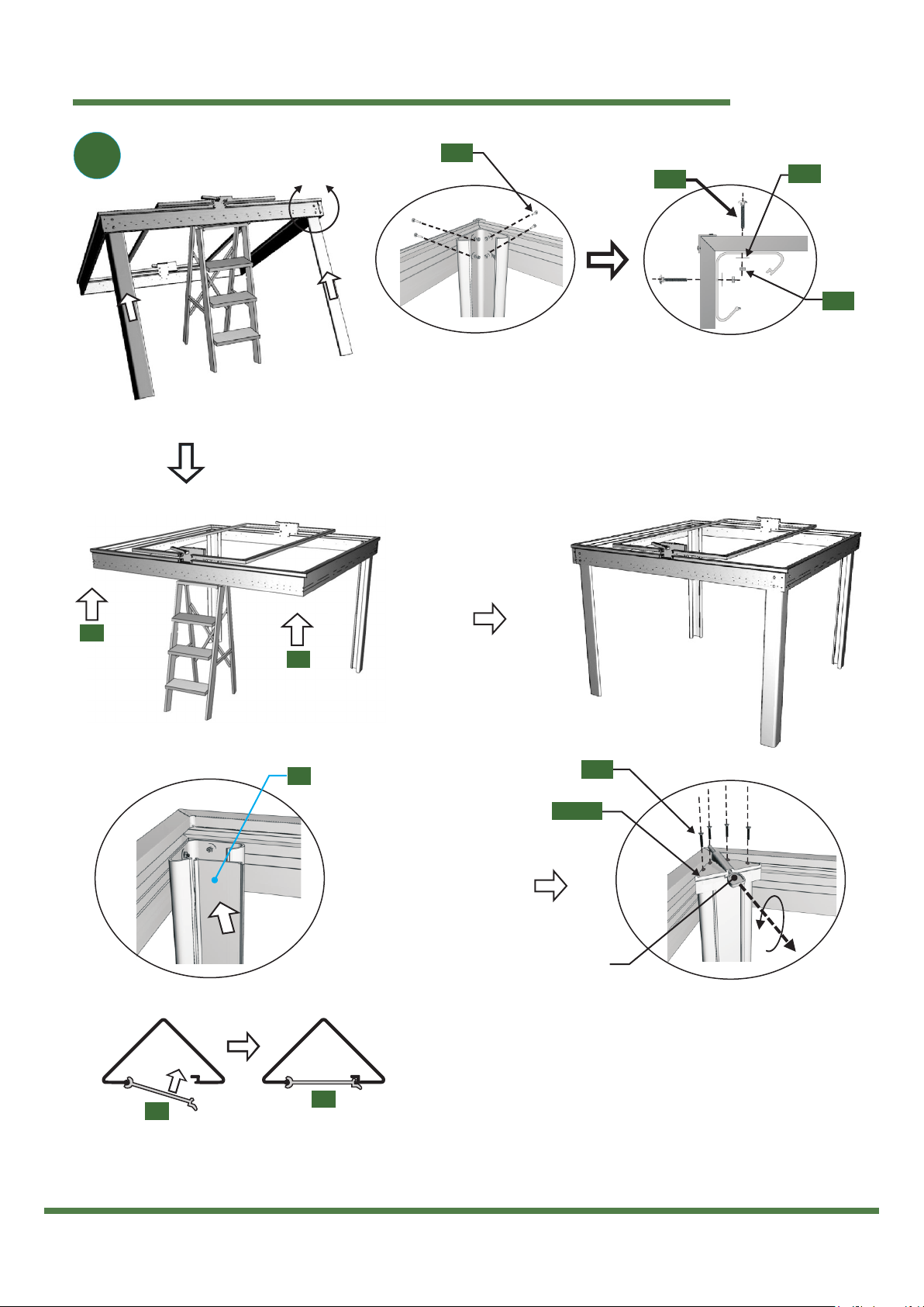
Attach one of the four corner posts (P1)to each corner of the structure using
hardware shown in the top right diagrams. This step may require a second
person or a ladder to lift the roof assembly in order to fix all four corner posts
(P1). See diagrams below for further assembly steps.
To complete the
post assembly, snap
together the corner
post (P1)and
corner post covers
(P2). Repeat step
for each corner.
Then fasten the top cover assembly (KC.07)on top of
each corner post (P1)DO NOT OVER TIGHTEN SCREWS.
The locking key can be in the unlocked position or
removed from the cover assembly by turning then
pulling it.

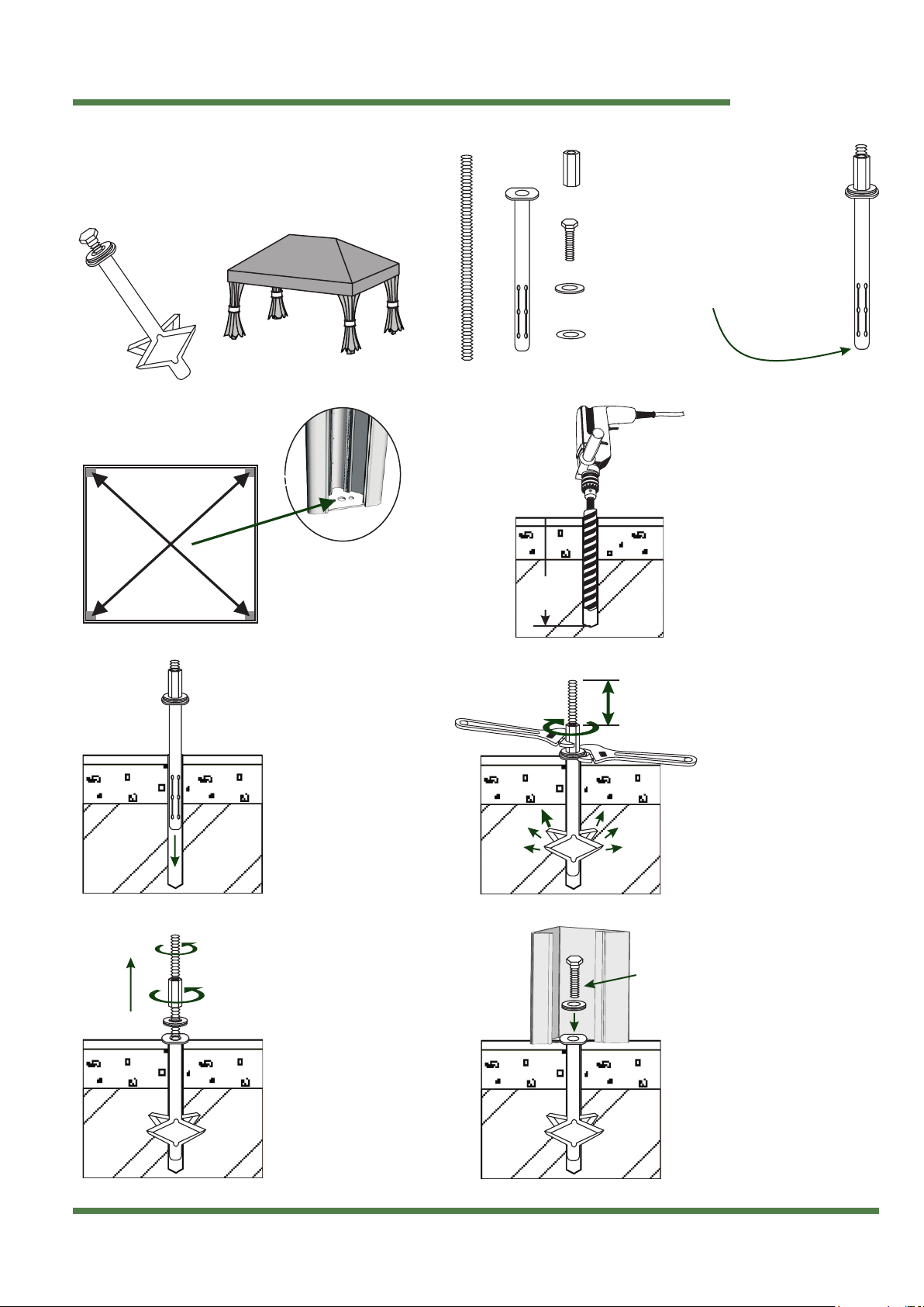
Anchoring the pavilion
BARLOW TYRIE
quality since 1920
www.teak.com Page 10 of 16
8
Make sure the structure is well aligned and levelled with the floor
as shown in the diagram below. Consult the section below for
recommendations on the type of anchorage required for fixing
the structure on the floor.
level
Ground Fixing
WOOD
OPTION A
WOOD DECK/FLOOR
Requirements:
8 (2 per plates) of each
- 5/16" x 2" wood screws
- 5/16" washers
CONCRETE
SOIL
OPTION B
CONCRETE/CEMENT FLOOR
The Permo Lock anchoring system is the recommended
method that offers a strong permanent solution for
anchoring your shelter and to protect it against the
wind. See next page for instructions on how to install this
anchor
C1
C2
C3
Remaining holes in
plate (AL005) are used
for xing the structure
on the oor
W
L
D
Distances W, L, and D are calculated
from centre to centre of plates (AL005)
Requirements:
8 (2 per plate) of each
- 3/8” x 11/2” expansion anchor
* use 1/2” cement drillm bit
Dimensions inches (cm)
W 111 (282)
L 138 (350)
D 177 (450)
C1 79 (200)
C2 114 (290)
C3 144 (366)
Anchoring the pavilion
BARLOW TYRIE
quality since 1920
www.teak.com Page11 of 16
Top View
3-1/4” (8.2cm)
Permo
®Lock Anchoring System
Insert the assembled
Permo Lock anchor
into the drilled hole
Unscrew the coupling
and rod completley
from the xed Permo
Lock anchor and
remove the two
washers
Place the corner of the structure
over the anchor and ax it using
the supplied ½” bolt and washers.
Grease the threads of the bolt
Screw in the coupling nut without
turning the rod and anchor.
The maximum opening of the
Permo Lock anchor occurs when
the rod extends 3¾” (8.2cm)
above the coupling nut
Drill a 1” x 19¾” (2.5cm x 50cm)
hole at each marked location
using a percussion drill with a
diamond tip masonry drill bit
Apply grease on threads
19¾”
(50cm)
x4
lock washer
x4
washer
x1
rod
x4
bolt
x1
coupling
x4
anchor
Position your assembled
structure on the chosen
location then mark the
center of each corner plate
Packaging Contents
One Permo Lock anchor comes
preassembled and ready to use
as shown on the right. Verify that
the rod end is ush with the end
of the anchor.

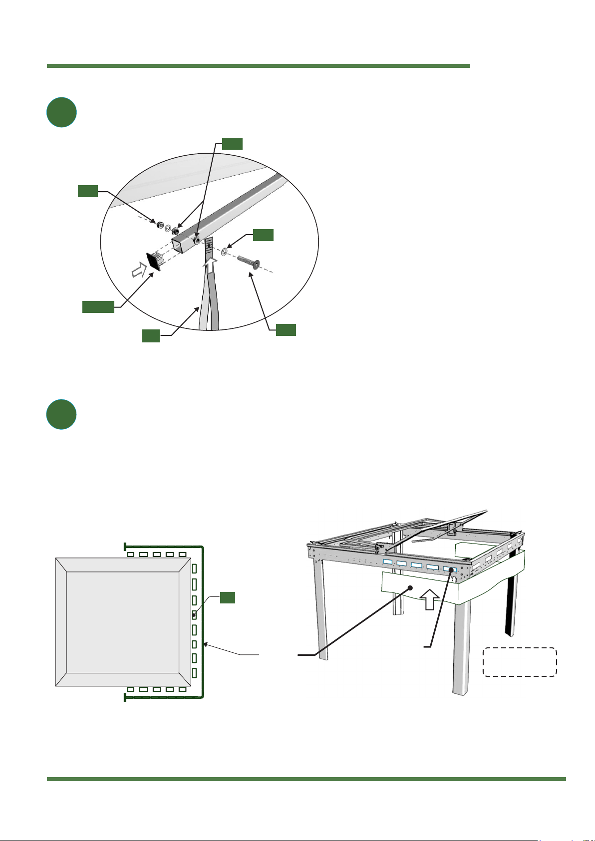
Final frame assembly
BARLOW TYRIE
quality since 1920
www.teak.com Page 12 of 16
H-H
I-I
9
View H-H
(step a)
View H-H
(step b)
Remove the guide
after installing the fork.
View H-H
(step c)
L1
L1
T4
View I-I
(TOP VIEW)
See
Through
View
Install the Plastic Finishing Cap
L1
10
016
006
011
009
019
003
026 020
PL01 1
PL01 1
PL005
PL010
PL012
KC.02L
Install the plastic fork on the (T4)truss assembly on the opening side. Locate the proper
position of the fork by using the fork installation guide as shown in views H-H. Then use the
self tapping screw (016)to fix the fork on the transverse truss member. Then insert the end
of the lever arm on the fork and fix the lever using hardware shown in view I-I. Repeat step
on other side for the dummy lever arm.
To complete the roof hinge mechanism, install the
plastic hinge cover (PL005)over the roof hinge using
screws (026).Then install side cover (PL010)and the
hole cap (020). Repeat step on both sides.
Final frame assembly
BARLOW TYRIE
quality since 1920
www.teak.com Page 13 of 16
12
R2
11
Velcro Strip
(top groove)
16” apart
Valance
TOP VIEW
Velcro Strip
(top groove) Roof will open
from this side
R3
002
005
010
018
PL013
Insert velcro strips at every 16” in the top groove of the beams. Then fix the
valance to the velcro strips (R3). Start from one end of the valance and
work your way around the frame assembly. See adjacent diagrams for detail.
Install the lever strap on the end of the lever arm
using hardware shown in the left diagram.
Then install the plastic cap (PL013)on the end
of both the lever and dummy lever arm.
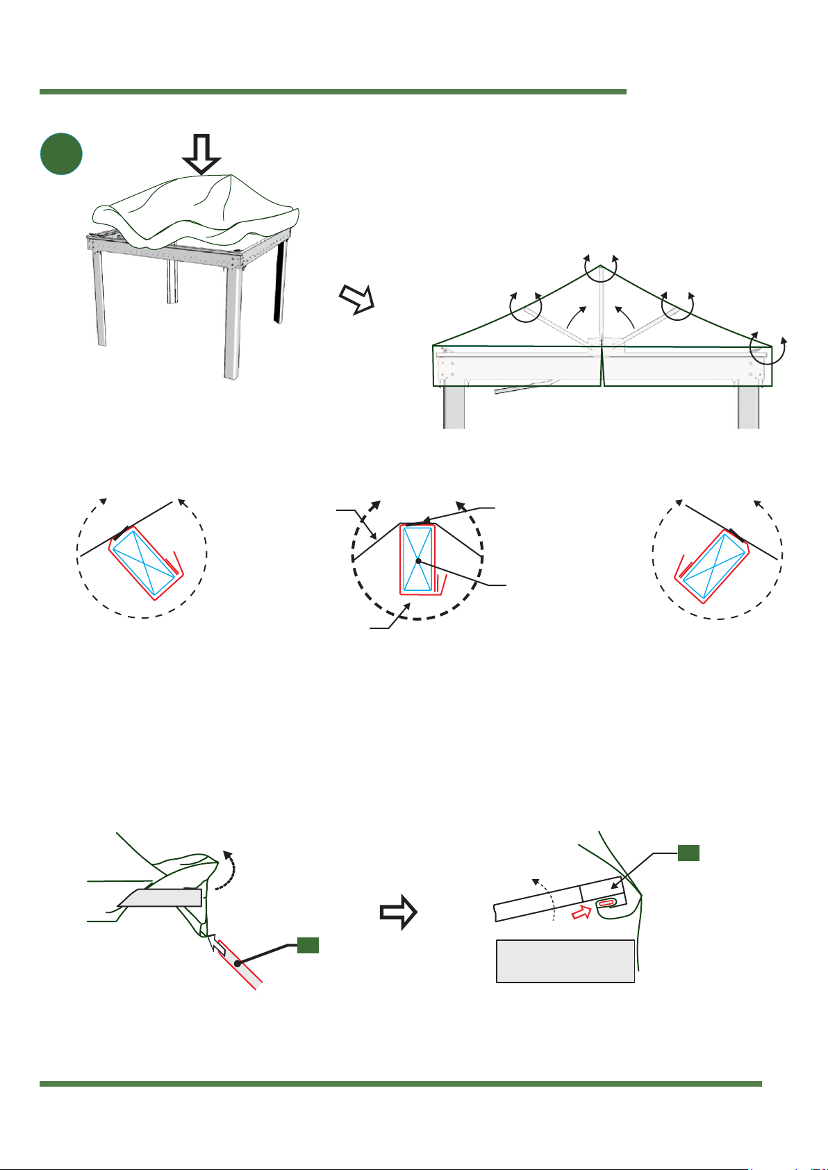
Installing the roof fabric
BARLOW TYRIE
quality since 1920
www.teak.com Page 14 of 16
SIDE VIEW
J-J
K-K
M-M
L-L
13
View L-L
View K-K View J-J
Roof Support
Velcro Strip
Roof Fabric Weld Line
View M-M
(Step a)
Insert a flat bar on each
end of the pocket
View M-M
(Step b)
R1
T2
The next step will give instructions on how to fix the roof cover to the frame assembly. Slide the flat bars
(R1)in the pocket of the fabric as shown in View M-M.Then raise the truss assembly and push the flat bar
and fabric into the groove of the transverse truss (T2). Then fix the velcro strip around the 2 roof supports
(T4). Note that the velcro should be fitted around the support as shown in views K-K (left hand side
support) and L-L (right hand side support). Then raise the middle roof support (T5)in its upright position
and fix the velcro around it as shown in view J-J.
Install the roof fabric cover over the frame assembly
with roof trusses down. Make sure that all 4 corners
of the roof fabric are aligned properly.
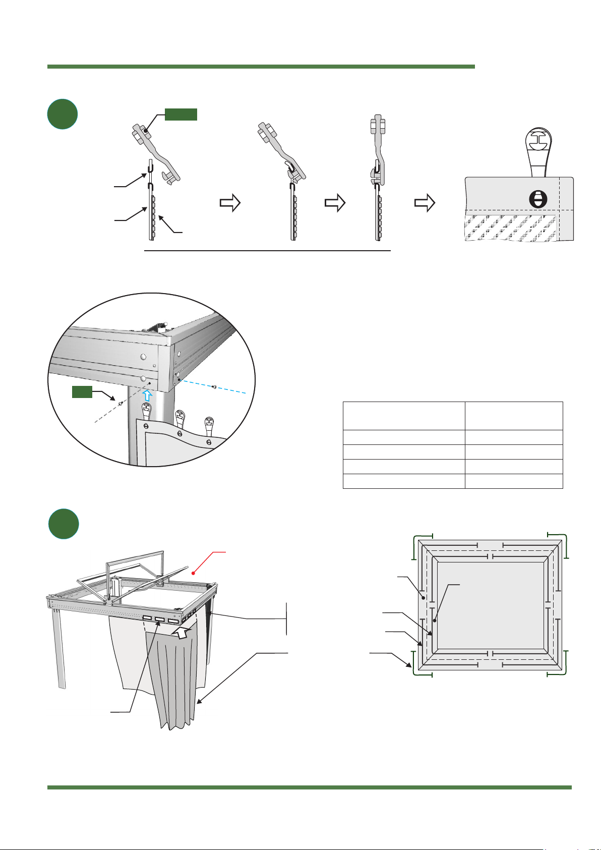
Installing the curtains
BARLOW TYRIE
quality since 1920
www.teak.com Page 15 of 16
15
14
025
outside rail
curtains on outside rail
decorative curtains
(installed using velcro strips
on bottom beam groove)
inside rail
curtains on inside rail TOP VIEW
Velcro Strips
Bottom Groove
16” apart
Profile View
Zipper
(Interior Side)
Metallic
Eyelet
Curtain
(Exterior Side)
Curtain
Exterior Side
Plastic Pulley Snap Pulley
in place
PL101
Roof fabric and valence
not shown for clarity
Install plastic pulleys (PL101)by snapping them in each metallic
curtain eyelet. Use long nose pliers to facilitate this operation.
Pulleys should be facing towards the curtain side on which the
zipper is located (see above steps). Then install each curtain
sections into the provided beam slots as shown by left hand
diagram. After installing all pulleys, block the access with the
screws (025)as shown in the diagram. Repeat step for each
corner. See next step (15) for curtain installation example
Curtain Type Rail
Decorative curtains Inner or Outer
Mosquito curtains Inner
Acrylic curtains Outer
Plastic curtains Inner or Outer
The decorative curtains are installed using velcro strips (R3)inserted
16” apart in the bottom groove of the beams similarly to the valance
in step 13. If you have purchased optional curtains (mesh netting,
transparent plastic or acrylic fabric) install them on the inside or
outside rail of the beams.
Installing the curtains
BARLOW TYRIE
quality since 1920
www.teak.com Page 16 of 16
Ref 3412
Barlow Tyrie Limited
Braintree
Essex CM7 2RN England
t: + 44 (0)1376 557 600
f: + 44 (0)870 460 1100
Barlow Tyrie Inc
1263 Glen Avenue Suite 230
Moorestown
NJ 08057 - 8101 USA
t: + 1 856 273 7878
f: + 1 856 273 9199
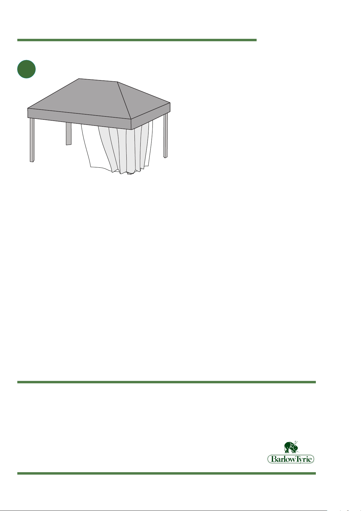
15 Install the decorative curtains on the iterior or exterior
rail of the beams (B1)and (B2). If you have purchased
optional curtains (mosquito netting, transparent plastic or
acrylic fabric) install them on the inside rail of the beams.
Table of contents
Other BarlowTyrie Patio Furniture manuals


Popular Patio Furniture manuals by other brands


GB
GB 5 Piece Ottoman Set instruction manual

Sunjoy
Sunjoy L-UB381PCM-50C manual

Patio Premier
Patio Premier Caspian 203016 instruction manual

Costway
Costway PATIOJOY OP70682 user manual

Doppler
Doppler Goliath 5x5 Assembly instructions and user guide

JAYDEN CREATION
JAYDEN CREATION HOUFC0185 Assembly instruction


