Barnstead Thermolyne Corporation Turner SP-870 User manual

1
Turner®Spectrophotometer
LT1102X6
BARNSTEAD|THERMOLYNE CORPORATION
SP-870
OPERATION MANUAL
Model # Voltage
SM110235 115V
SM110230-33 230V
with European cord set
6/97

2

3
Table of Contents
Introduction .......................................................................................................................................................4
Safety Information.......................................................................................................................................4
General Usage............................................................................................................................................4
Theory ........................................................................................................................................................5
Working Principle ........................................................................................................................................7
Specifications..............................................................................................................................................8
Instrument Description................................................................................................................................9
Front Panel Description ........................................................................................................................9
Keyboard ............................................................................................................................................10
Rear Panel Description......................................................................................................................11
Environmental Conditions .........................................................................................................................11
Unpacking .................................................................................................................................................12
Standard Equipment .................................................................................................................................12
General Cleaning ......................................................................................................................................12
Operation.........................................................................................................................................................13
Pre-operation Check Procedures ..............................................................................................................13
Startup ......................................................................................................................................................14
Concentration Mode..................................................................................................................................17
Factor Mode..............................................................................................................................................18
Memory Setup ..........................................................................................................................................20
Auxiliary Function for Memory Setup ........................................................................................................21
Selection of Memory Mode .......................................................................................................................22
Printout of Memory ...................................................................................................................................23
Users Functions........................................................................................................................................23
Stand-by mode ...................................................................................................................................23
I.D. Number Setting Mode ..................................................................................................................24
Wavelength Check Mode....................................................................................................................25
Maintenance....................................................................................................................................................27
Replacing the Lamp ..................................................................................................................................27
Realigning the Lamp .................................................................................................................................27
RS-232 and Printer..........................................................................................................................................29
External Output Setup ..............................................................................................................................29
External Output.........................................................................................................................................32
Message Code Interpretation....................................................................................................................33
Warranty..........................................................................................................................................................34

4
Caution
Cautions alert you to a
possibility of damage to the
equipment.
Note
Notes alert you to pertinent
facts and conditions.
Warning
Warnings alert you to a
possibility of personal injury.
Introduction
Congratulations on your purchase of a Turner®
Spectrophotometer.
Introduction
SP-870 is a digital microprocessor-controlled
visible spectrophotometer providing
photometric read-out of Transmittance,
Absorbance, Concentration and converted
Factor with the following unique features.
- automatic filter selection
- auto zero
- internal wavelength calibration
- error messages
- RS-232C/printer interfaces
- 20 x 2 LCD display
- (30) user-programmed text modes
The unit is designed to do a number of jobs
within your laboratory. Please read the
instructions carefully to ensure that you receive
maximum benefit from it. Also, be sure to fill out
and return the enclosed warranty registration
card. We would like to receive the information
requested, and it will help us assure you of
proper warranty coverage.
Safety Information
Your Turner Spectrophotometer has been
designed with function, reliability, and safety in
mind. It is the user's responsibility to install it in
conformance with local electrical codes. For
safe operation, please pay attention to the alert
boxes throughout the manual.
General usage
Do not use this product for anything other than
its intended usage.
5
INTRODUCTION
Theory
A spectrophotometer is primarily used to identify
unknown substances and determine their con-
centrations. The following principles outline how
this is accomplished.
Matter absorbs energy when it interacts with an
energy source such as light. Due to its distinctive
atomic structure, each substance only absorbs
energy between certain levels. Since energy is
inversely proportional to wavelength, E=hc/ λ
(where h is Plank’s constant, c is the speed of
light, and λis the wavelength of light), every
substance has a characteristic absorption spec-
trum.
For example, hydrogen absorbs light at the fol-
lowing wavelengths in the visible region:
410.7nm, 433.8nm, 485.7nm and 657.9nm. We
can verify the existence of hydrogen in an un-
known sample by comparing the wavelengths
actually absorbed by the unknown sample to
hydrogen’s known absorption spectrum.
Therefore, a device, namely your spectrophotom-
eter, is required to measure absorption spec-
trums in order to identify an unknown substance.
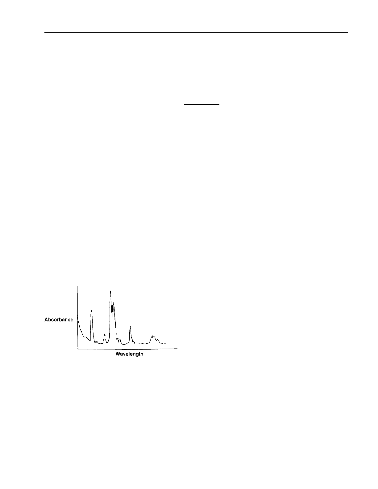
A spectrophotometer measures the amount of
light absorbed at distinct wavelengths of incident
light. As a result, a graph of the amount of ab-
sorbed light at various wavelengths can be plot-
ted (absorbance vs. wavelength, as shown in Fig.
1.) This is known as an absorption spectrum.
Such a graph can be used to identify the pres-
ence of a particular substance.
The concentration of an unknown sample can
also be determined. When a light beam is inci-
dent to a sample, part is absorbed and part is
Fig. 1
6
transmitted. The transmittance (T) is defined as
the ratio of the transmitted intensity of the light
beam (It) to the initial intensity of the light beam
(Io), or T= It/ Io. The absorbance (A) is defined as
A=log (1/T). It is found that absorbance is directly
proportional to concentration: A= ε b c where A
is the absorbance, c is the concentration (mol/L),
b is the pathlength of the sample (cm), and εis a
constant called the molar absorptivity (L/mol-cm).
This linear relationship between absorbance and
concentration is called Beer’s Law.
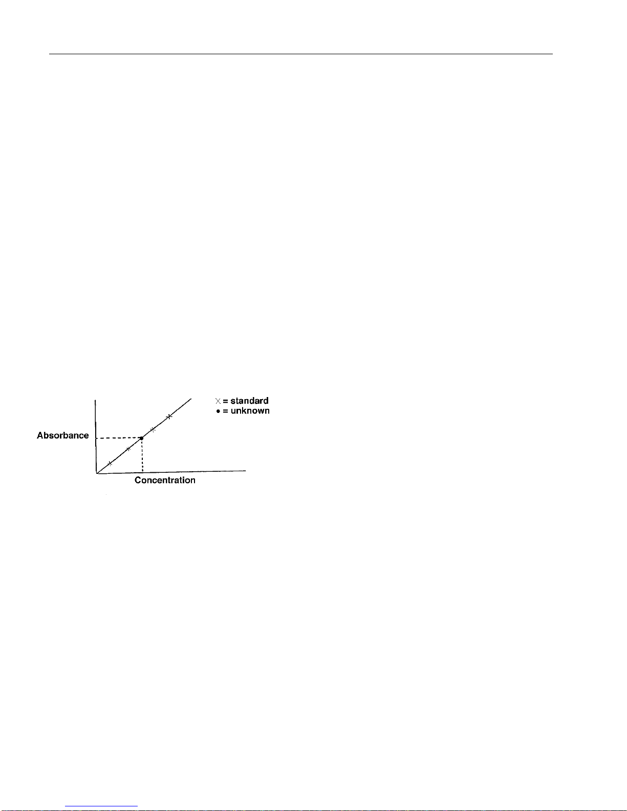
The concentration of an unknown sample can be
determined by using Beer’s Law and preparing a
standard curve. A standard curve is prepared by
measuring the absorbance of a series of known
standards at different concentrations. The absor-
bance vs. concentration is then plotted for each
standard (represented by x in Fig. 2). A linear
relationship between the absorbance and con-
centration should then be observed (straight line
in Fig. 2) and a linear standard curve is thus
prepared. It is then possible to determine the
concentration of an unknown sample by measur-
ing its absorbance and comparing it to the stan-
dard curve. The concentration of the unknown
can then be determined as shown by the dotted
line in Fig. 2.
Therefore, if we have a “standard” sample with a
known absorbance and concentration, it is easy
to determine an unknown concentration of the
same substance by measuring its absorbance
and applying Beer’s Law.
INTRODUCTION
Fig. 2 Standard Curve
(Beer’s Law)
Fig. 2 Standard Curve
(Beer’s Law)
7
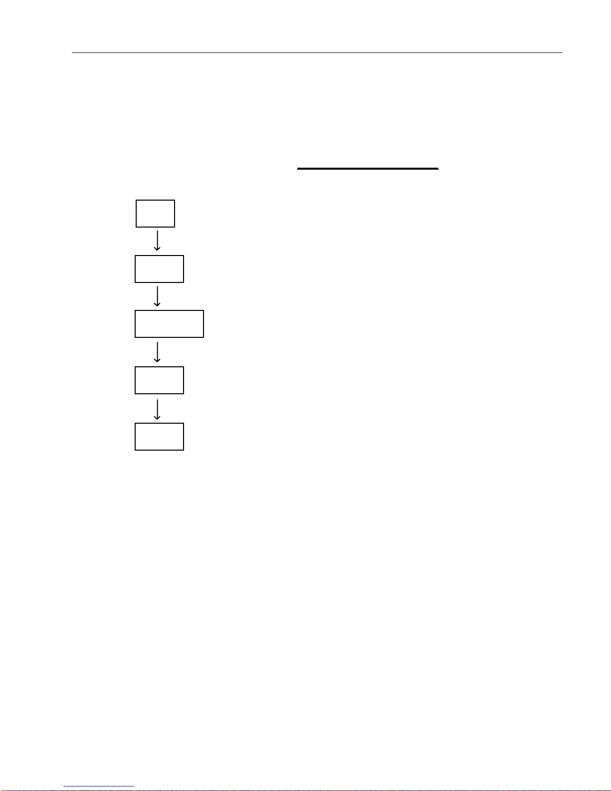
Working Principle
A spectrophotometer basically consists of five
parts: a light source to supply electromagnetic
energy, a monochromator to isolate the wave-
length of interest and a stray light filter to elimi-
nate the unwanted second order radiation, a
sample compartment to accommodate the
sample solution, a detector to receive the trans-
mitted light and convert it to electrical signal, and
either a digital or analog display to indicate absor-
bance and transmittance. The block diagram to
the left illustrates the relationship among these
parts.
In your spectrophotometer, a light beam from the
lamp is focused on the entrance slit of the mono-
chromator and passes into the monochromator,
where the collimating mirror directs the beam to
the grating. The grating disperses the light beam
to produce the spectrum, a portion of which is
focused onto the exit slit of the monochromator
by the collimating mirror. From here the beam is
passed through a stray light filter which helps
eliminate unwanted second order radiation. The
beam then enters the sample compartment
where it is passed through the sample. The
sample may absorb a portion of the light beam.
Upon leaving the sample compartment, the beam
then falls on the silicon diode detector. The
intensity of the light beam causes the detector to
produce an electrical signal. This electrical signal
is then converted to transmittance or absorbance
and displayed.
INTRODUCTION
Light
Source
Mono
chomator
Sample
Compartment
Detector
Display

8
Specifications
Wavelength Range 330-999nm
Bandwidth Pass 5nm (nominal)
Wavelength Accuracy +/- 2nm
Wavelength Repeatability +/- 0.5nm
Wavelength Setting Automatic
Zero & Blank Setting Automatic
Filter Selection Automatic
Display 20 x 2 LCD
ModesTransmittance 0~100%T
Absorbance 0.000~2.000A
Concentration 0~19,999
Factor 1~19,999
Photometric Accuracy 1% at 1A
Photometric Linearity 1%
Stability Drifting 0.003A/hr
after half hour warm-
up at 0A
Signal Processing Digital,
Microprocessor
Stray Light 0.1%T typical at
340nm,
<0.5%T 330-999nm
Cuvettes A. Round cuvettes
10-13mm in diameter;
B. Square cuvettes
12.5 x 12.5 x 45mm,
1 cm path length
(optional-34F01-04);
C. Vacuum empty
cuvette (optional-
AYX9)
Power 115/230V~. 50/
60Hz (switchable)
Analog Output 0.00~1.00V
Interface RS-232C, Printer
Dimension 400mm(W) x
300mm(D)
x 145mm(H)
Weight 9.0kgs
INTRODUCTION
9
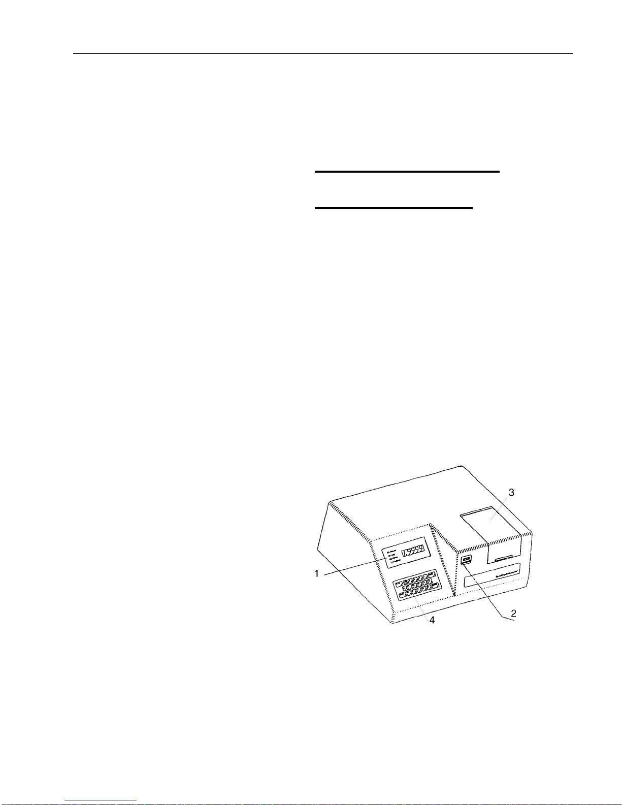
Instrument Description
Front Panel Description
1. DISPLAY panel - Displays wavelength, %T,
ABS, CONC, or FACTOR value.
2. Power indicator - Indicates power ON/OFF
and STANDBY mode. the indicator lights in
green when the power is on for operation and
will turn red when the instrument in under
STANDBY status.
3. SAMPLE Compartment - For round cuvettes
or square cuvettes.
4.Keyboard - For data entry. See Keyboard
information, next page, for details.
INTRODUCTION

10
Keyboard
1. FUNC A. F0: Standby Mode
B. F1: ID number setting
C. F2: Wavelength Check
2. 100%T/OA - Sets the instruments to 100%
Transmittance or Zero Absorbance.
3. PRINT - Directs the output to RS-232C and
Printer interface. (*See dip switch setting on the
rear panel in the enclosed appendix.)
4.λλ
λλ
λnm - Sets desired wavelength.
5.A- Selects Absorbance mode.
6.T- Selects Transmittance mode.
7.C- Selects Concentration mode.
8. F- Selects Factor mode.
9. SHIFT + Any Arrow Key - Searches memory
mode in memory setting or reading.
10. SHIFT + C - Enters memory reading.
11. SHIFT+ F - Enters memory setting.
12. ESC - Clear input or quit operation mode.
13. 0-9 - Numerical value.
14. . - Decimal point
15. ENTER - Enters the keyed in numerical
values into the system.
INTRODUCTION

11
Rear Panel Description
1. RS 232-C
2 Printer
3. Analog Output
4. Fan
5. Power Switch
6. Fuse
7. Power Socket
8. 115V/230V Voltage Switch
Environmental Conditions
Operating: 17°C - 27°C; 20% - 80%
relative humidity, non-condensing. Installation
Category II (over-voltage) in accordance
with IEC 664. Pollution Degree 2 in
accordance with IEC 664. Altitude limit: 2,000
meters.
Storage: -25°C - 65°C; 10% - 85% relative
humidity.
INTRODUCTION

12
Unpacking
The package contains the items stated below.
Unpack the carton and inspect carefully. If any
part is damaged or missing, contact your dealer
immediately.
Save the packing materials in case the unit may
need to be repacked or returned for service.
Standard Equipment
QTY DESCRIPTION PART #
1 SP870 Spectrophotometer
115V SM110235
230V SM110230-33
1 Power cord 115V CRX72
230V CRX70
6 Round borosilicate cuvettes 34F01-15
1 Fuse 115V/1.0 Amp 5120-0016
1 Fuse 230/0.5 Amp FZX35
1 Operator’s manual LT1102X6
General cleaning instructions
Wipe exterior surfaces with a dampened cloth
containing a mild soap solution.
INTRODUCTION

13
Operation
Pre-operation check procedure
Your spectrophotometer has been fully checked
and aligned before shipping. However, a short
pre-check should be performed before the first
use of this instrument.
1.Carefully unpack your spectrophotometer and
check every item against the Standard Equip-
ment list.
2.Place the spectrophotometer on a solid and
level surface in a dry, clean environment.
3. Confirm that the correct line voltage is set and
correct fuse is installed. 1.0A for 115V, or 0.5A
for 230V.
4.Plug the AC power cord into the rear of the unit
and plug into a grounded wall socket.
5.Turn the power ON by switching the rocker
switch at the rear of the spectrophotometer.
6. Allow the spectrophotometer to warm up for at
least 20 minutes to stabilize the electronic
components.
7. Set the wavelength dial to 340nm. Press the
100% T/0A button. The display should show
100.0 while in the TRANS (transmittance)
mode and 0.000 for the ABS (absorbance)
mode. Indicator lights below the main display
indicate whether the unit is in the transmittance
or in the absorbance mode. To change the
mode setting, press the T button for transmit-
tance or the A button for absorbance on the
front panel of the unit.
8.If the LED display shows Err3 or Err4, the lamp
alignment may have shifted during shipment.
Refer to the section entitled Realigning the

14
Lamp for more information.
Startup
1.Turn the power on. A complete initialization
calibration of the instrument for electronic
checks and Zero Order alignment will be
automatically performed. This process will
take approximately 2 minutes. The display
will run through:
2. After the calibration is done the system will
directly enter the first memory mode which is
pre-set at 440nm and F1. The display should
show:
The instrument is now ready for use. Refer
to details in related sections.
OPERATION
MODEL 870
VERSION: 1.6 AB
MODEL 870
SYSTEM TEST PASS 0
MODEL 870
** CALIBRATION**
440 T
WAITING BLANK

15
OPERATION
Note
It is suggested to run the
Wavelength Check Mode to
ensure the 000.0 nm position
after a large number of
samples have been run or
after stand-by mode.
Operation procedures
Turn the power on, and allow the instrument
to warm up for at least 20 minutes.
After an internal self-test for initializaiton
calibration of the instrument is performed,
the system will proceed to first memory
mode automatically. The first memory mode
is pre-set for wavelength at 440 nm and for
Factor at 1 when the instrument is delivered.
The display should show:
Percent Transmittance and
Absorbance mode
1.Fill a cuvette with the solvent that will be
used to zero the spectrophotometer. This is
the blank (or background) solvent that your
sample is dissolved in.
2.Place the cuvette in the cuvette holder in the
sample compartment. Close the sample
compartment lid.
3.Press (λnm) button, enter the numerical
value (330-999) of the wavelength and press
the ENTER button. If a mistake is made in
the key-in process, press the ESC button to
clear the display for a new entry.
4.Select Transmittance or Absorbance mode
by pressing the (T) or (A) button.
440 T
WAITING BLANK

16
5.Zero the instrument using the blank solution by
pressing the (100%T/OA) button. The display
should show:
XXX TCALB or XXX ACALB
then should read
XXX 100.0T or XXX 0.000A
(Transmittance mode) (Absorbance mode)
6.Carefully open the sample compartment and
remove the cuvette.
7.Place the cuvette with solution to be measured
in the sample compartment and close the
sample compartment door. The cuvette should
be oriented in the same position as the cuvette
used to zero the instrument with the blank
solution. The display will show the Transmit-
tance or Absorbance immediately. Record the
value and remove the cuvette.
8.Repeat step 7 for further samples to be tested
at the same wavelength. For a different wave-
length, steps 1 through 7 should be repeated.
9.After the test is complete, turn off the power; or,
set the instrument at Standby mode if further
test will be performed soon.
(Refer to Standby mode section.)
OPERATION

17
Concentration Mode
1.Fill a cuvette with the solvent that will be
used to zero the spectrophotometer. This is
the blank (or background) solvent that your
sample is dissolved in.
2.Place the cuvette in the cuvette holder in the
sample compartment. Close the sample
compartment lid.
3.Press (λnm) button, enter the numerical
value (330-999) of the wavelength and press
the ENTER button. If a mistake is made in
the key-in process, press the ESC button to
clear the display for a new entry.
4.Select Transmittance or Absorbance mode
by pressing the (T) or (A) button.
5.Zero the instrument using the blank solution
by pressing the (100%T/OA) button. The
display should show:
XXX TCALB or XXX ACALB
then should read
XXX 100.0T or XXX 0.000A
(Transmittance mode) (Absorbance mode)
6.Carefully open the sample compartment and
remove the cuvette.
7.Fill a cuvette with a Standard solution of
known concentration and place the cuvette
in the sample compartment.
OPERATION
18
8.Select Concentration mode by pressing (C)
button and key in the concentration of the
Standard solution. Press the ENTER button.
The display should show:
9.Place the cuvette with unknown solution to be
measured in sample compartment and close it.
The display will show the Concentration of the
solution immediately. Record the value and
remove the cuvette.
10. Repeat set 9 for further samples to be tested
at the same wavelength. For a different wave
length, steps 1 through 9 should be repeated.
11.After the test is completed, turn off the power;
or, set the instrument to STANDBY mode if
further tests will be performed soon. (Refer to
Standby mode section.)
Factor mode
1.Fill a cuvette with the solvent that will be used
to zero the spectrophotometer. This is the
blank (or background) solvent that your
sample is dissolved in.
2.Place the cuvette in the cuvette holder in the
sample compartment. Close the sample com-
partment lid.
3.Press (λnm) button, enter the numerical value
(330-999) of the wavelength and press the
ENTER button. If a mistake is made in the key-
in process, press the ESC button to clear the
display for a new entry.
XXX OC XXX XXXXXC
Note
1. If a mistake is made in the key-
in, press ESC button to clear
for new entry.
2. The Standard value range is 0-
19999.
3. If so desired, press (F) button
and record the calculated
FACTOR value in memory to
enable measurement with
same reagent to be made at
later time without
restandardization. The calcu-
lated FACTOR value range
should be at 1-19999.
OPERATION

19
4.Select Transmittance or Absorbance mode
by pressing the (T) or (A) button.
5.Zero the instrument using the blank solution
by pressing the (100%T/OA) button. The
display should show:
XXX TCALB or XXX ACALB
then should read
XXX 100.0T or XXX 0.000A
(Transmittance mode) (Absorbance mode)
6.Carefully open the sample compartment and
remove the cuvette.
7.Place the cuvette with solution to be mea-
sured in sample compartment and close the
sample compartment lid.
8.Select Factor mode by Pressing (F). The
display should show:
9.Key in factor value (1-19999) and press the
ENTER button. (Refer to Memory Reading.)
10.System will automatically shift to Concentra-
tion mode, and the display will show the
Concentration of the Solution. This calcu-
lated concentration is a result of the mea-
sured Absorbance multiplied by the entered
(or pre-stored) factor value. Record the
XXX 1
FACTOR: _ _
OPERATION
20
Memory Setup
SP-870 provides thirty (30) user-programmable
memory test modes. To enter MEMORY
SETUP, press the SHIFT and F buttons simul-
taneously. The display should show:
Each memory comprises four items:
1. > sign that indicates current memory mode
2. memory mode number (01-30)
3. wavelength
4. factor value
Memories normally are undefined when the
instrument is delivered. An undefined memory
is followed with “None”.
1.Press the ENTER button to set up the current
memory mode that the > sign indicates.
2.Key in the desired data respectively for wave-
length and factor value, each key-in should be
followed by pressing the ENTER button.
>01 440NM F XXXXXX
02 NONE
Note
To exit Memory Setup mode
press ESC.
value and remove the cuvette. The multiplied
Concentration value range should be 0-19999.
If this is exceeded, re-define the factor value.
11. Repeat steps 7 & 10 for further samples to be
tested at the same wavelength and factor. For
a different wavelength or factor, steps 1
through 10 should be repeated.
12. After the test is complete, turn off the power;
or, set the instrument at Standby mode if
further testing will be performed soon. (Refer
to Standby mode section.)
OPERATION
This manual suits for next models
2
Table of contents


