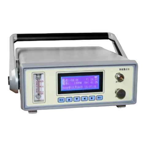
Huazheng HZDZ-S3 User manual

HZDZ-S3 Portable Three Phase
Power Quality Analyzer
USER MANUAL
aHuazheng Electric Manufacturing(Baoding) Co.,Ltd

Content
Preface............................................................................................................................................... 1
I Functions and Features................................................................................................................ 2
II Technical Specifications.............................................................................................................. 4
III Structural Appearance................................................................................................................ 5
(I) Size of the shell structure and terminal arrangement................................................... 5
(II) Keyboard..............................................................................................................................8
IV LCD screen...................................................................................................................................9
V Usage........................................................................................................................................... 18
(I) Measurement of parameters of three-phase four-wire connection mode devices 19
(II) Measurement of parameters of three-phase three-wire connection mode devices20
(III) Measurement of waveform display section................................................................ 21
(IV) Measurement of spectrum analysis section...............................................................21
(V) Analysis of voltage harmonic section........................................................................... 22
(VI) Analysis of current harmonic section.......................................................................... 22
(VII) Unbalance measurement section...............................................................................23
VI Battery Maintenance and Charging....................................................................................... 24
VII Notes.......................................................................................................................................... 25

1
Preface
Power quality refers to the quality of the AC power supply via the utility grid to the user,
which normally means the good or bad situation of the electric energy in transmission line. Power
quality problems are mainly caused by the load side of the terminal. For example, impact reactive
load will lead to serious fluctuates to power network voltage, and decrease the quality of power
supply.
With the development of power electronics technology, on one hand, it brought positive side
to the modern industrial energy efficiency and energy conversion. On the other hand, while the
power electronic devices are widely used in all walks of life, it also has brought new and more
serious damage to the power quality, and has become the main source of harmonic in grid.
The increasing use of rectifiers, frequency control devices, electric arc furnaces, electric
railway and a variety of power electronic devices in each distribution system, impact the
electricity network or called power pollution. It causes voltage instability, over-voltage, generates
harmonics and so on. Harmonic makes efficiency of electricity production, transmission and
utilization reduce, so that the electrical equipment will be overheat, vibration and making noise,
and insulation aging, shortened life expectancy, and even failure or burned. Harmonics can also
cause localized power system an occurrence or series resonant parallel resonance, so that the
harmonic content is amplified, resulting in capacitors and other equipment destroyed.
Electrical properties of non-linear, impact resistance and unbalanced of these kind of load,
causes serious pollution to the quality of power supply. Thus, eliminating the higher harmonic
problem in supply and distribution system has a very positive meaning in improving the power
quality issues and ensuring power system security, stability and economic operation.
On the other hand, electrical equipments in modern industrial, commercial and residential
users are more sensitive to power quality, and have a higher requirement of quality of power
supply. Currently, harmonics, electromagnetic interference, power factor reduction have been tied
to the three hazard of the power system.

2
When it is interfered or contaminated, grid power quality can’t reach the national standards,
so it has to be targeted on the grid power quality improvement. To understand the actual situation
of power quality, you must have the appropriate equipment to test and analysis the actual situation.
Counter the domestic condition, our company developed the professional power quality analysis
instrument, which is suitable for the country. The following will illustrate the specific
performances, parameters, methods of use on the power quality analyzer in detail.
I Functions and Features
1. The instrument is designed as a high-precision test equipment to detect grid waveform
distortion occurrence, the harmonic content , voltage fluctuations and flicker and phase imbalance
of power quality problems; It also includes electrical parameters testing, vector analysis functions.
2. It can accurately measure a variety of electrical parameters, such as voltage, current, active
power, reactive power, phase angle, power factor, frequency, etc.
3. It can display the vector diagram of the measured voltage and current , by analyzing which
users can judge if the metering device wiring is correct or not.
4. Current is measured by using the clamp transformers. You can easily and securely do the
measurement, because of the use of clamp current transformers, without connecting the current
loop. Depending on the user's measurement range, you can be equipped with different range of
clamps.
5. Measurement and analysis of the AC power quality from the utility grid to client can be
done easily, its measurement and analysis: frequency deviation, voltage deviation, voltage
fluctuations, flicker, three-phase voltage unbalance factor and harmonic.
6. It can display single-phase voltage, current waveform and can display three-phase voltage
and current waveform at the same time.
7. All testing interface is functioned with a screen lock feature to facilitate reading and
analysis of user data.
8. Load fluctuations monitoring: It can measure and analysis fluctuations on the utility grid

3
power quality caused by a variety of electrical equipment at different operating conditions. Record
and store trend of electrical parameter, such as voltage, current, active power, reactive power,
apparent power, frequency, and phase at a regular time.
9. It can do electrical equipment adjustment and dynamic monitoring during operation, and
help users to solve the power adjustment and commission process problems.
10. It can measure and analysis the dynamic parameters of reactive power compensation and
filtering devices in the power system, and make quantitative evaluation of its features and
technical specifications.
11. Users can set different storage interval, and it will successively store data according to the
set time interval;
12. High-capacity data storage is equipped inside. It can store 18 consecutive months or more
according to one minute interval, which meets the needs of long-term monitoring testing points.
13. The instrument includes a USB connector, which can be easily used to copy the data
directly to the backstage management computer.
14. It coordinates with powerful data management software, and can directly upload real-time
sampling data to backstage management compute, which can do a more comprehensive and rapid
treatment in the background.
15. It has a calendar, clock function, which can display date and time in real-time. You can
detect at the scene while saving test data and results, and upload to a computer via serial connector,
then realize computerized data management through the backstage management software
(optional), with powerful reporting capabilities.
16. Large-screen imported color LCD is used as a display, and Chinese user interface is
equipped with Chinese character prompt, multi-parameter display LCD interface, friendly
interactive interface.
17. LCD will automatically enter power-saving mode when there are 3 minutes without
operation in order to maximize the extending battery life.
18. It uses conductive silicone keypad, which feels good, long life, reasonable design, and

4
easy to operate.
19. High-capacity, high-performance lithium-ion rechargeable battery is equipped inside,
which can continuously work for more than 10 hours if the battery is fully charged.
20. It has a small size, light weight, easy to carry. It can be used both as site testing
measurement and as the standard measurement equipment in laboratory.
II Technical Specifications
1. Input characteristics
Voltage measuring range: 0~200V~800V, automatic cutting gear.
Current measurement range
Clamp transformers (three types): 5A / 25A (standard)
100A / 500A (optional)
400A / 2000A (optional)
Phase angle measuring range: 0 ~ 359.99 °.
Frequency measurement range: 45 ~ 55Hz.
Voltage channels: three-channel (UA、UB、UC).
Current channels: three-channel (IA、IB、IC).
Maximum harmonic analysis times: 63 times.
Maximum continuous storage period in 1 minute interval: 18 months.
2. Accuracy
Measurement of electrical parameters section:
Voltage: ± 0.2%
Frequency: ± 0.01Hz
Current, power: ± 0.5%
Phase: ± 0.2 °
Power quality section:
Fundamental voltage tolerance: ≤0.5% F.S.

5
Fundamental current tolerance: ≤1% F.S.
Phase between fundamental voltage and current measurement error: ≤0.2 °
Percentage of harmonic voltage measurement error: ≤0.1%
Percentage of harmonic current measurement error: ≤0.2%
Three phase voltage unbalance error: ≤0.2%
Voltage deviation error: ≤0.2%
Voltage fluctuation error: ≤0.2%
3. Working temperature: -10 ℃~ + 40 ℃
4. Charging Power: 220V AC, 45Hz-55Hz frequency
5. Host Power: ≤3VA
6. Battery maximum working time: ≤10 hours
7. Insulation:
1) The insulation resistance between the voltage, current input terminal and the housing
≤100MΩ.
2) Withstand 1.5KV (valid value) with power frequency on operating power input and the shell,
which lasts one minute.
8. Size: 320mm × 240mm × 130mm
9. Weight: 2.0Kg
III Structural Appearance
(I) Size of the shell structure and terminal arrangement
Front elevation of the instrument appearance as shown:

6
(电能质量测试仪:power quality analyzer 参数设置:Parameter Setting 电气测
试 : Electrical Testing 谐 波 测 试 : Harmonics Testing
频谱分析:Spectrum Analysis 波形显示:Waveform Display 矢量分
析:Vector Analysis 电压闪变:Voltage Flicker
历史数据:Historical Data 国标查询:GB Query 移动存储:Removable Storage 磁盘查
询:Disk Reading 系统校准:System Calibration 存储:storage 查询:query
退出:quit 设置:set 切换:shift 自检:self-checking
帮助:help 【测试】及【存储】相关参数输入:[Test]and [storage]related parameters input)
The front top of the instrument panel is a a liquid crystal display, and the below is key area,
and the top part of the instrument is wiring area, and the right is other ports (communication,
charging, USB) area.
Top wiring terminals district as shown:

7
信号:Signal A 相钳:phase-A clamp B 相钳:phase-B clamp
C 相钳:phase-C clamp
Including: Voltage input terminals: UA 、UB、UC、UN; Clamp current transformer ports
(phase-A clamp, phase-B clamp, phase-C clamp); Signal port(reserved function).
A right side view of the instrument is
shown at right, other parts of interface of the
lower portion can be exposed when the rear
holder is opened, which includes the
following three parts: (232 串行口:232 serial
port
充电器接口:Connector of the charger
USB 接口:USB connector)
● 232 serial port (used to upload stored data
to computer): It can also be used to update
the program; Note: This connection to the
computer must be equipped with special
communication cable, which can be found in the box after you buy this instrument. Common
serial cable is not suitable for this connection.
●Connector of the charger is for connecting with the charger. Please connect the charger to this
connector for charging the instrument when power is low.
● USB connector can be connected to a computer via a dedicated data line. The storage card in the
instrument will be used as high-capacity removable memory. The side view as shown at right:
● Size of the crates of the instruments as shown at right:

8
(II) Keyboard
There are 30 keys on the keyboard, namely: switch, storage, query, set, ↑, ↓, ←, → , quit,
self-checking , help, figure 1, figure 2 (ABC), figure 3 (DEF), figure 4 (GHI), figure 5 (JKL),
figure 6 (MNO), figure 7 (PQRS), figure 8 (TUV), figure 9 (WXYZ), figure 0, the decimal point,
#, auxiliary functions button F1, F2, F3, F4, F5.
Each key function as follows:
Switching key: It is used to control power of the instrument on and off. Usage : On - press this
button and then release; Off - press and hold this button for 2 seconds (the center of the screen will
display "System Shutdown"), then release.
↑, ↓, ←, → keys: Moves the cursor; It is used to move the cursor in the main menu to point to a
function menu, and press Enter key to enter the corresponding function; Up and down keys are
used to switching current option, and left and right keys are to change the value in the parameter
setting screen. In addition, ↓ can also be used to display the subdirectory menu.
Key: Enter key; Press this button to display the subdirectory menu in the main menu. Press this
key to enter the selected function in the subdirectory menu. In addition, this button is to start and
end input when you input certain parameters.
Exit key: Return key, press this key and it goes directly back to the main menu.
Storage key: It is used to store the results as records.
Query key: Pressing this key in the main menu will directly lead you to the <Disk Consult>
function screen.
Setting key: Pressing this key in the main menu will directly lead you to the <Parameter Setting>
function screen.
Toggle key: Reserved function, not available.
Self-test key: It is used for burning fonts during instrument debugging process, which is of no use
for users.
Help key: Pressing this key in the main menu will directly lead you to the <Help File> function

9
screen.
Figure (character) key: It is used for inputting parameter settings (you can input figures or
characters).
Decimal point key: It is used to input a decimal point when setting parameters.
# Key: Reserved function, not available.
F1, F2, F3, F4, F5 keys: Auxiliary function keys (shortcuts). It is used to quickly access the
auxiliary function interface or implement corresponding function as prompt message says.
When no key is pressed within five minutes the liquid crystal display will automatically enter
power saving mode, press any key to restore the display.
IV LCD screen
1. Main menu:
When the power is on screen display will be
shown as right. A total of twelve options are in
main menu, which are: Parameter Setting,
Electrical Testing, Harmonics Testing, Spectrum
Analysis, Waveform Display, Vector Analysis,
(电能质量测试仪:power quality analyzer
参数设置:Parameter Setting 电气测试:Electrical Testing
谐波测试:Harmonics Testing 频谱分析:Spectrum Analysis
波形显示:Waveform Display 矢量分析:Vector Analysis 电压闪变:Voltage Flicker
历史数据:Historical Data 国标查询:GB Query 移动存储:Removable Storage 磁盘查
询:Disk Reading 系统校准:System Calibration
【测试】及【存储】相关参数输入:[Test] and [storage] related parameters input)
Press ←, →, ↑, ↓ keys to change these options including Voltage Flicker, Historical Data, GB
Query, Removable Storage, Disk Reading and System Calibration. It will be highlighted when the

10
name of the menu is selected. Related functions prompt will be shown in the blue bar at the
bottom of the screen. Press Enter key to enter the corresponding functional testing and setting;
Upper right corner of the screen shows the remaining power percentage of the built-in
rechargeable battery, according to which users can determine whether you need to charge the
instrument; Left side of the battery shows the current date and time; Left side of time shows the
voltage and current measuring gear of the instrument. It is adaptive to change the voltage gear. If
you need to change the current gear, you can enter the "Parameter Setting" option to manually set;
Upper left corner of the screen displays the name of the instrument, the instrument number and
software version.
2. "Parameter Setting" Interface:
"Parameter Setting" interface as shown at
right, is used to adjust the data to be determined
before trial, including: PT ratio, CT ratio,
Connection Mode, Current Input, Rated Voltage,
Short Circuit Capacity, Power Supply Capacity,
Agreement Capacity, Setting Date, Setting Time, Substation Name, Line Name, File Name,
Storage Rates, Start Storing.
(电能质量测试仪:power quality analyzer
PT 变比:PT ratio CT 变比:CT ratio 接线方式:Connection Mode 三元
件:three-element 三相四线:three-phase four-wire 电流输入:Current Input 小钳:small
clamp 额定电压:Rated Voltage 一次:primary side 短路容量:Short
Circuit Capacity 供电容量:Power Supply Capacity 协议容量:Agreement
Capacity 设置日期:Setting Date 变电站名:Substation Name 线
路名称:Line Name 文件名称:File Name 存储速率:Storage Rates 分钟:minute 帧:
frame 开始存储:Start Storing 否:No 按【回车】修改,【退出】返回:Press [Enter] to
modify,[Quit] to back)
●PT ratio: refers to the ratio value of voltage transformer used by the device under test. Input

11
method: Press Enter key to make the figures turn red, then press the corresponding figure keys to
enter data, and then press Enter key to complete.
●CT ratio: refers to the ratio value of current transformer used by the device under test. Input
method: Press Enter key to make the figures turn red, then press the corresponding figure keys to
enter data, and then press Enter key to complete.
● Connection Mode: refers to the connection mode of the device under test, including: two-
element delta connection, three-element delta connection, three-element star connection. By using
←, → key among several ways you can switch to the desired mode selected.
● Current Input: refers to the measurement method of current, including: 5A clamp
measurement, 25A clamp measurement, 100A medium clamp measurement, 500A medium clamp
measurement, 400A large clamp measurement (non-standard), 2000A large clamp measurement
(non-standard), a total of six kinds of options. By using ←, → key among several ways you can
switch to the desired mode selected.
● Rated Voltage: refers to the rated voltage on the primary side of the device under test. There
are seven stalls as 0.38, 6, 10, 35, 66, 110, 220kV. Press ←, → key to switch options, and select
the desired gear.
● Short Circuit Capacity: Short-circuit capacity refers to apparent power when three-phase short
circuit happened on some certain point when the electric power system is in the specified run
mode. It is a characteristic parameter which shows the ability of the power supply system, whose
value is equal to the short-circuit current multiplied by rated voltage on the point of the
three-phase short circuit.
● Power Supply Capacity: Load of power supply system, generally refers to capacity of the
step-down transformer on the user side, kVAs for example.
● Agreement Capacity: Maximum active power or apparent power supply of electricity applied
by users and authorized by supplier.
● Setting Date: Input method: Press Enter key to make the figures turn red, then press the
corresponding figure keys to enter data, and then press Enter key to complete. For example:

12
January 12, 2013, enter 20130112 to confirm.
● Setting Time: Input method: Press Enter key to make the figures turn red, then press the
corresponding figure keys to enter data, and then press Enter key to complete. For example:
11:45:07, enter 114507 to confirm.
● Substation Name: refers to the name of the substation where the tests are done, which is used
to distinguish between the saved results. It is composed by figures and characters, which can be
any combination. Enter corresponding figure / character keys directly. Input method: Press Enter
key to make the contents turn red, then input the corresponding keys, and then press Enter key to
complete.
● Line Name: refers to the number of circuit under test, which is used together with "Substation
Name" to distinguish between the saved results. It is composed by figures and characters, which
can be any combination. Enter corresponding figure / character keys directly. Input method: Press
Enter key to make the contents turn red, then input the corresponding keys, and then press Enter
key to complete.
● File Name: refers to the name of a file stored in recording. It is composed by figures and
characters, which can be any combination. Enter corresponding figure / character keys directly. Do
not enter the file extension. The program will automatically add.
● Storage Rates: refers to the time interval in storing the test data, whose minimum interval is
one minute and maximum interval is five minutes. Press ←, → key to switch options, and select
the desired time interval.
● Start Storing: refers to the switch of storage function setting. When you select "Yes", the
storage function is on and will start storing data automatically. When you select "No", the storage
function is off and will stop storing data.
Press Enter key to enter the corresponding setting, and press Escape key to return to the main
menu.
3. "Electrical Testing" interface:

13
To display data from measured point of the
transformer primary side and secondary side,
Figure at right shows three-phase voltage, current
amplitude from primary side, and phase angle
between each phase voltage and current;
(电能质量测试仪: power quality analyzer
测试参数【一次】:measurement parameter[primary side] 测试功率【一次】:measurement
power[primary side] 综合参数:comprehensive parameter
按【上下】移动,【左右】改变,【退出】返回:Press [up and down] to move,[left and right]
to modify,[quit] to back)
It shows each phase active power, reactive power, apparent power, total active power Ph, total
reactive power Qhand total apparent power Sh; It also shows zero-sequence voltage Uo,
zero-sequence current Io; Positive sequence voltage U1, positive sequence current I1;
Negative-sequence voltage U2, negative-sequence current I2; Voltage and current unbalance # U, #
i; Measured frequency, and total power factor. Press F1 to lock the current screen for easy reading,
and press F2 to continue to refresh, and press F3 to see the primary data, and press F4 to switch to
the secondary side of the interface. Press Escape key to return to the main menu.
4. "Harmonics Test" Interface:
Voltage and current harmonics display as
shown at right, displays each harmonic content
of each phase voltage and current signal (from
left to right, saying A, B, C phase voltage and A,
B, C phase current), in which THD refers to
voltage or current
waveform distortion of each phase (i.e. total harmonic distortion), and RMS refers to voltage or
current effective value of each phase, and 01 times means a fundamental voltage or current
(represented by the actual amplitude), and the following times means the values of the other

14
various harmonics, which is represented as valid value and percentage of the fundamental wave. It
represents 1-63 harmonics in tabular. You can switch tabular of (01-21) times, (22-42) times and
(43-63) of the harmonic content by ↑, ↓ keys.
Press F1 to lock the current screen for easy reading, and press F2 to continue to refresh.
Press Escape key to return to the main menu.
5. "Spectrum Analysis" Interface:
"Spectrum Analyzer" interface as shown at
right, shows the harmonic content of phase-A
voltage, phase-B voltage, phase-C voltage,
phase-A current, phase-B current and phase-C
current in histogram.
(电能质量测试仪:power quality analyzer 通道:
channel 按【F1】锁定,【上下】改变范围,【左右】换通道:Press [F1] to lock, [up and down]
to change range, [left and right]to change channel)
The column of adjacent times of the harmonic content can be distinguished by different colors.
There are 10 colors for each group cycle. We just displayed in the histogram 32 times, for 32 or
more times harmonic can hardly be used in general. UA-UB-UC-IA-IB-ICindicates the current
measurement channel (available through ←, → keys to change the selected channel). The ordinate
scale of 0% -10% represents the percentage of each harmonic component. The fundamental
component always corresponds to 100% scale (It is amplified in display when the harmonic
component are all less than 10%, i.e. as a full scale of 10%; It is on a normal scale display when
there are more than one harmonic component greater than 10%, i.e. that is 100% as full scale). The
abscissa indicates the times of harmonics. Numbers on the right shows the total harmonic
distortion value THD, effective value and the value of 1-64 times of each harmonic (with ↑ , ↓
keys to flip). Signal with no distortion should display first harmonic (fundamental). It is tested
with Ua, Ub, Uc of the three voltage channels and Ia, Ib, Ic of the three current measurement
channels.

15
The bottom of the screen is an indicator, indicating that operations can be carried out. Press
F1 to lock the current screen for easy reading, and press F2 to continue to refresh so that you can
continue viewing from 1 to 64 harmonic phase voltage. Press Escape key to return to the main
menu.
6. "Waveform Display" Interface:
"Waveform Display" interface is
(电能质量测试仪:power quality analyzer 实时
波形:real-time waveform 自动缩放:
Auto scale
按【F1】锁定,【上下】选择通道,【退出】
返回主菜单:press[F1]to lock,[up and down] to
select channel,[quit] to back to main menu)
shown at right. Actual waveform of the measured analog can be displayed in this screen. The
current waveform is in real-time to refresh, to visually show distortion of the measured signal
(whether distortion or whether truncated). It is currently displayed as A, B, C three-phase with all
of the voltage and current waveform, with ↑ , ↓ keys to switch between different phases; It can be
switched to the phase-A voltage and current waveform, phase-B voltage and current waveform,
phase-C voltage and current waveform, A, B, C three-phase voltage waveform ,A, B, C
three-phase current waveform. It can be used as a simple oscilloscope to use.
The bottom of the screen is an indicator, indicating that operations can be carried out.
7. "Vector Analysis" interface:
"Vector Analysis" interface is shown at right.
Measured vector hexagonal diagram of device
under test is displayed in this screen. It also
shows vector relationship of three-phase voltage
(two-phase when two elements),
(电能质量测试仪:power quality analyzer

16
测试数据:measurement data 接线分析:connection analysis 相序:phase sequence 更
正系数:modifying coefficient 感性:susceptible 容性:tolerance 按【F1】锁定,【退出】
返回:press[F1] to lock,[quit] to back) three-phase current (two-phase when two elements) and
each phase angle reference to Ua(Uab when two elements). You can visually determine whether
the three-phase metering device is correct, and tolerance-susceptible relationship between loads of
each phase through this screen. The above shows three-phase four-wire vector diagram when the
wiring is all correct under standard resistive load. Press F1 to lock the current screen, and press F2
to continue to refresh. Press Escape key to return to the main menu.
8. "Voltage Flicker" Interface
Extension function: No function in this version.
9. "Historical Data" interface
"Historical Data" interface is shown at right.
Press F1 to view the electrical parameters from a
historical moment, including: each phase voltage
and current, zero-sequence voltage and current,
positive sequence voltage and current,
(电能质量测试仪:power quality analyzer
电气参数:electrical parameter 记录总数:record total number 当前记录:current record 测
试时间:Testing time 按【上下】浏览,【左右】快进,【退出】返回:press[up and down]to
browse,[left and right]to fast forward, [quit] to back)
negative sequence voltage and current, unbalance of voltage and current, active power and
reactive power of each phase, total active power, reactive power, frequency, total power factor,
phase angle between each phase voltage and current, and power factor. Press F2 to view 1 up to 16
times distortion and harmonics of voltage and current. Press F3 to see 17 to 32 harmonics, F4 to
see 33 to 48 harmonics, F5 to see 49 to 64 harmonics.
The bottom of the screen is an indicator. Press ↑, ↓ keys and you can browse history one by
one, ←, → key to fast forward looking, Escape key to return to the main menu.

17
10. "GB Query" Interface
(电能质量测试仪:power quality
analyzer 额定电压:rated
voltage 短路容量:short circuit capacity
供电容量:Power Supply Capacity 协
议容量:Agreement Capacity 次数:times
电流:current 电压:voltage 按【退出】返
回主菜单:press[quit] back to main menu)
"GB Query" Interface as shown at right, shows international standard of 2 to 25 times voltage and
current harmonic calculated based on the nominal voltage, short circuit capacity, power supply
capacity, agreement capacity (setting in "Parameter Setting"). If the harmonics value is lower than
the standard, then it’s compliance with international standards.
11. "Removable Storage" Interface
This interface serves as a connection
between a built-in large-capacity data storage
card and a computer. The instrument can be
directly used as a USB storage device.
(电能质量测试仪:power quality analyzer
USB 和电脑接好线后,按【F5】键;按【退出】
键返回主菜单:Be sure to connect the USB connector to a computer, press[F5]; press[quit] back
to main menu)
Note: Be sure to connect the USB connector to a computer via a dedicated cable (not an ordinary
USB cable) before you can press F5 to online operation, or it may cause a death phenomenon as
long-awaiting, which must be shut down to end the crash.
12. "Disk Reading" Interface
"Disk Reading" interface is shown at
right. This feature screen is used to view the

18
contents of the internal memory of the instrument, including name of the stored files, size, total
disk capacity and remaining available storage space.
(电能质量测试仪:power quality analyzer 文件夹列表:folder list 无文件
夹:No folders 记录文件夹列表:record folder list 按【退出】返回
主菜单:press[quit]back to main menu)
13. "System Calibration" Interface
Not available for users, omit.
V Usage
The instrument is equipped with a four-core voltage testing line and three current test clamps
(can be equipped to six as required). Voltage test lead is used to access to the measured voltage
signal. When testing with current clamp in the field, each current clamp corresponds to a clamp
connector, non interchangeable, otherwise it will affect test accuracy. There’s a roundel sticker in
the middle of each clamp, exhibiting phase and polarity of the clamp (The superscript N end is
current outflow end. Pay attention to the polarity on use of wiring, because reversal would affect
the test results).
Should be noted during the testing:
1. Intercalate the current test clamp before testing. Clip testing signal before intercalating the
current test clamp is strictly prohibited. It’s equivalent to open circuit on the secondary side of
current test clamp, which is prone to a high-pressure of open circuit and damage the instrument.
Take off all current test clamp and then unplug connected to the host after the test is completed.
2. To ensure the accuracy of each channel, the test clamp should be one-to-one correspondence,
which means properly inserting each current clamp to the corresponding outlet. Exchanging
different input socket will reduce accuracy of the test, but it generally does not exceed the
measurement accuracy of ± 2% after crossing.
3. The test line must access to the voltage terminal of the instrument when accessing to the
voltage signal, and then access to the voltage terminal of the device under test; You must
Table of contents
Other Huazheng Measuring Instrument manuals

Huazheng
Huazheng HZ1434 User manual

Huazheng
Huazheng HZX52AA User manual

Huazheng
Huazheng HZ2831 User manual

Huazheng
Huazheng HPC500 User manual

Huazheng
Huazheng HZ-600A User manual

Huazheng
Huazheng HZSF-641 User manual

Huazheng
Huazheng HZSM-701 User manual

Huazheng
Huazheng HZ-8700 User manual

Huazheng
Huazheng HZCT-100B User manual

Huazheng
Huazheng PHS-2F User manual