Barrett 2018 Specification sheet

No part of this manual may be copied, transcribed, translated or reproduced in any manner or form whatsoever, for
commercial purposes, without obtaining prior written permission from Barrett Communications Pty. Ltd. However,
limited copying is permitted for private use providing authorship is acknowledged.
The 2018 Mobile magnetic loop HF antenna design is protected by Australian patent 2001100423. Unlicensed
replication of the design is expressly forbidden.
BCM201800/6
© Barrett Communications
Head Office:
Barrett Communications Pty Ltd
47 Discovery Drive, Bibra Lake, WA 6163 Australia
Tel: +61 8 9434 1700 Fax: +61 8 9418 6757
Email: [email protected]
www.barrettcommunications.com.au

2 of 31
Introduction...........................................................................................................................................4
Features.........................................................................................................................................4
General ..........................................................................................................................................5
About this Guide...........................................................................................................................6
Glossary of Terms........................................................................................................................6
Warnings and Advice...........................................................................................................................7
High Radio Frequency Voltages .................................................................................................7
Power Supply Cables...................................................................................................................7
Radio Frequency Field Exposure................................................................................................7
Explosion Hazard .........................................................................................................................7
Storage of Other Goods...............................................................................................................8
Frequency Hopping Use ..............................................................................................................8
Operation in Rough Terrain.........................................................................................................8
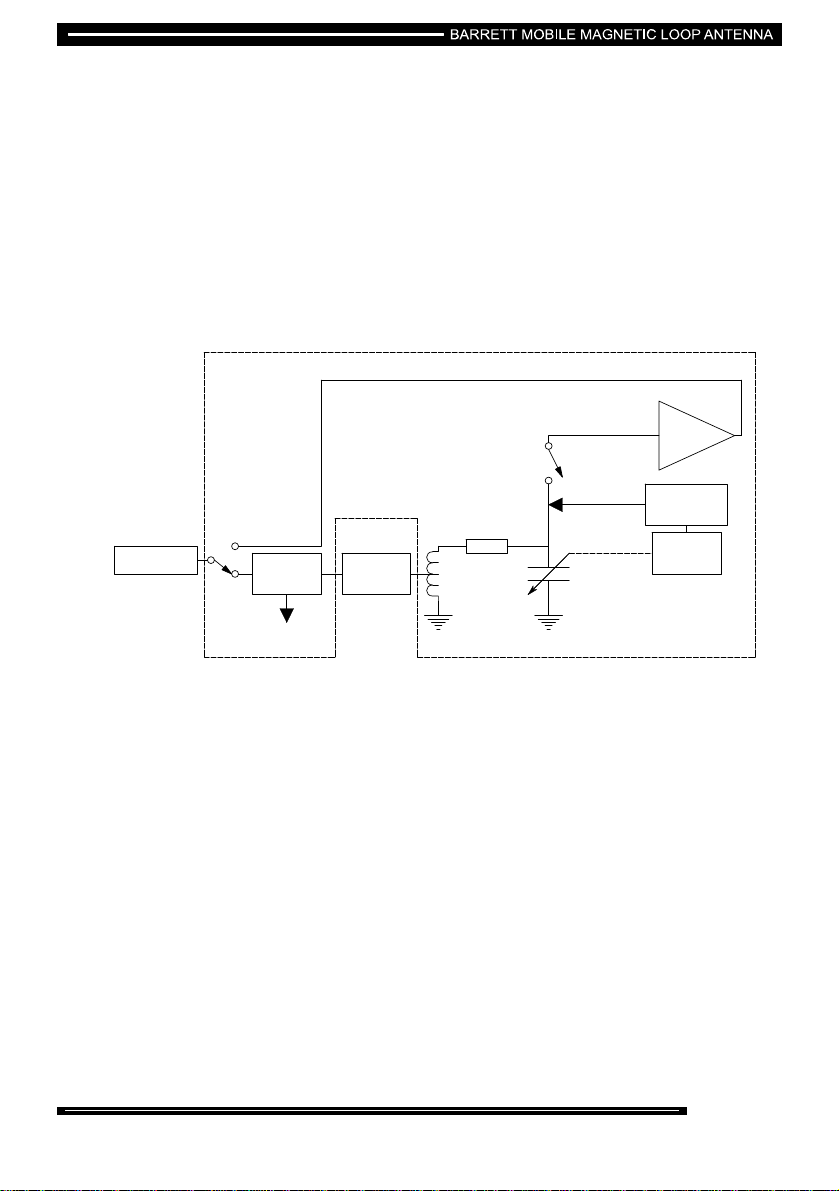
Overview................................................................................................................................................9
Installation...........................................................................................................................................11
Fitting on Vehicles With Gutters.......................................................................................................11
Setting Up the Roof Rack ..........................................................................................................12
Preparing the Vehicle.................................................................................................................15
Fitting on Vehicles Without Gutters .................................................................................................17
Setting Up the Roof Rack ..........................................................................................................17
Preparing the Vehicle.................................................................................................................18
Maintenance........................................................................................................................................21
Removal of Rack.................................................................................................................................21
Retrofitting the 2018 Barrett Mobile Magnetic Loop Antenna........................................................21
Cabling.................................................................................................................................................22
Operation.............................................................................................................................................23
To Deploy the Antenna ..............................................................................................................23
To Stow the Antenna..................................................................................................................24
Barrett Transceiver to 2018 Barrett Mobile Magnetic Loop Antenna Setup .................................25
Supported Barrett Transceivers................................................................................................25
Testing and Troubleshooting............................................................................................................25
Troubleshooting .........................................................................................................................26
Testing.........................................................................................................................................27
External Connectors ..........................................................................................................................28
ATU 6 Pin Connector Functions ...............................................................................................28
Internal Jumper Configurations................................................................................................28

3 of 31
J5 Jumper Settings ....................................................................................................................29
J6 Jumper Settings (DC Supply on RF Cable).........................................................................29
J7 Jumper Settings ....................................................................................................................29
Parts List .............................................................................................................................................30
Technical Specifications....................................................................................................................31

Introduction
Features
•Highly efficient antenna, radiating 10 dB to 14 dB more than whip antennas.
•Simpler installation – no need to weld on a mounting plate for a whip, and no separate tuner
to install. Installation is therefore quicker and cheaper, and the system can be moved
simply between vehicles.
•Free roof rack with every package. The antenna can be used as a conventional roof rack
for storing luggage.
•Eliminates Skip Zones. A HF system that can be used in ranges from 0-1,000 km and more.
•Increased immunity to ignition and power line noise.
•Broadband low-noise scan amplifier.
4 of 31

5 of 31
General
The 2018 Mobile magnetic loop HF antenna is a technological breakthrough in vehicle-based HF radio
communications.
The 2018 Mobile magnetic loop HF antenna is available in a range of packages for fixed or removable
installations and can be used with Barrett 2000 Series transceivers. The removable package can be
installed without any drilling of holes in the vehicle.
The 2018 Mobile magnetic loop HF antenna is without doubt the best type of antenna for vehicular
NVIS (Near Vertical Incidence Skywave) operations. Skip zones are eliminated and coverage (with
the correct selection of frequency) is from 0 to 1000 km or more. Within this range it is significantly
more efficient than any whip-type vehicle antenna; producing considerably more transmit and receive
strength. The actual gain over whip antenna systems varies between +10 dB and +14 dB. The
benefit to the user is that it radiates significantly more power, and magnifies received signal strength,
giving overall performance much higher than can be achieved from any vehicle whip antenna system.
The 2018 Mobile magnetic loop HF antenna tuner unit is a highly efficient, continuously variable
capacitor unit which is driven by a stepper motor to give the best VSWR reading.
When tuned the 2018 antenna has a very narrow bandwidth for transmission. This characteristic is
also beneficial for reception since interfering signals separated from the tuned frequency by just a few
percent are greatly attenuated, protecting the front end of the receiver from intermodulation and
blocking effects.
During scanning the tuning capacitor is bypassed and a low-noise high-linearity amplifier is inserted in
the signal path. This allows the loop to retain its desirable NVIS characteristics whilst offering
broadband receive capability.

6 of 31
About this Guide
The main purpose of this guide is to provide you with all the information you require to ensure optimum
performance from your 2018 Mobile magnetic loop HF antenna.
The Guide explains in detail how to operate the 2018 antenna once it has been installed by an
authorised Barrett Communications representative.
The Guide also covers the basic principles of installation. However, we recommend that the
installation of your 2018 be carried out by a qualified Barrett Communications representative.
Glossary of Terms
ATU Antenna Tuning Unit
HF High Frequency
kHz Kilohertz (measure of frequency)
km Kilometre
MHz Megahertz (measure of frequency)
PEP Peak envelope power
PTT Press To Talk
Selcall Selective Call
Telcall Selective Call with Telephone Call facility
VSWR Voltage standing wave ratio
W Watt

Warnings and Advice
High Radio Frequency Voltages
When transmitting, radio-frequency voltages up to 1500 V RMS are present on the
radiating arm and associated cables of the 2018 Barrett Mobile Magnetic Loop
Antenna. These voltages are sufficient to cause electrocution or severe radio
frequency burns. Personnel must not under any circumstances come into contact
with the radiating arm of the antenna or the associated cables when the unit is in
operation.
Power Supply Cables
7 of 31
High Frequency transceivers require adequate supply current. It is essential that the
supplied cables are utilised to reduce the likelihood of system malfunction. Please
use the specified cables.
Radio Frequency Field Exposure
The 2018 Barrett Mobile Magnetic Loop Antenna produces high localized radio
frequency fields. As long as personnel are beneath the level of the roof rack,
exposure to fields will be well below safe operating levels.
Explosion Hazard
Highly flammable materials (e.g. gasoline, petrol, butane, propane, etc) should
not be stored on the roof rack when the equipment is in operation. The induced
RF field during transmission may cause spark discharges between adjacent metal
objects which could cause the material to ignite.

Storage of Other Goods
Goods of normal flammability (for example, tyres, suitcases, tents, etc) may be
safely stored on the roof rack, however metallic items like tent poles should be
secured away from the radiating arm to avoid degrading the ATU's performance.
They should be secured so that no movement occurs during transport.
Important:- Do not use the antenna arm to tie any object down. Keep goods
at least 0.3 m away from antenna arm and feed cables.
Frequency Hopping Use
8 of 31
Due to the narrow operating bandwidth of the loop antennae, they are not ideally
suited for frequency hopping use. However, at higher frequencies (approximately 7
MHz) and when there is adequate signal to noise ratio, adequate results may be
obtained.
Operation in Rough Terrain
Following operation in rough terrain, the mounting leg fixings should be checked and
re-secured as necessary.

Overview
The roof rack has been designed by Barrett Communications Pty. Ltd. as an integral part of the
antenna system. The ground plane is a heavy-duty aluminium mesh floor, welded to an enclosing
frame which maximises current in the radiating loop. The 2018 Barrett Mobile Magnetic Loop Antenna
shields and isolates vehicle ignition noise and interference from adjacent power lines providing greater
communication clarity.
The 2018 Barrett Mobile Magnetic Loop Antenna can be fitted to almost any surface. The roof rack
comes in a range of mounting bracket options. Solutions are available that will allow clamping to the
roofs of 4WD’s, sedans, buses, trucks and prime movers. It is designed to minimise head wind noise
with an angled deflector mounted on the front of the unit.
A simplified diagram of the parts that make up the 2018 Mobile magnetic loop HF antenna is shown
below.
9 of 31

The antenna consists of a looped aluminium arm hinged to an aluminium roof rack which forms an
effective ground plane.
RF and DC power is supplied to the 2018 Barrett Mobile Magnetic Loop Antenna system from the
transceiver. The vehicle battery supplies the transceiver with its DC power.
The RF Feed box receives its RF input from the transceiver via the ATU box and an RF coaxial cable
(supplied). The output is connected to the antenna.
The scan amplifier and the associated receive-transmit switching are incorporated within the ATU.
A simplified block diagram of the circuit is shown below:
10 of 31
Stepper
motor
Microprocessor
control
Scan
amplifier
Antenna
Radiation resistance +
ohmic losses
Variable
capacitor
RF
feedbox
Voltage
sample
SWR
detector
Transceiver
To
microprocessor
Antenna tuner
Transmit/receive
switching
The antenna is effectively a parallel tuned resonant circuit, with the feed-point forming an auto-
transformer in the inductive arm of the tank. Resonance is achieved through a stepper driven variable
capacitor. An on-board microprocessor monitors loop current, with final tune based on system VSWR.

Installation
Fitting on Vehicles With Gutters
M10 Strut Nut (x16)
Leg Spacer
Viewing Hole
Leg Mount (x8)
M10 Flat Washer (x16)
M10 Star Washer (x16)
M10x25 Hex Bolt (x16)
M10x30 Hex Bolt
(for leg spacer)
U Bolt (x8)
Nylon (x16)
Full Gutter Support (x16)
Full Gutter Support Nylon (x16)
Locating Rod
(welded)
Clamp (x8)
M6 Flat Washer (x16)
M6 Nyloc Nut (x16)
M6 PVC Cap (x16)
Exploded Diagram of the Leg Mount Assembly
11 of 31

Setting Up the Roof Rack
Turn the rack upside down on either a bench or soft, non-abrasive surface.
The diagram below illustrates how the strut nut works. Position the legs in the correct channels and
tighten to the correct tension.
M10 Bolt
M10 Star Washer
Part of Leg Mount
Strut Nut
Mounting Channel
M10 Washer
Serrated Grooves
Turned down lips
M10 Bolt
M10 Star Washer
Part of Leg Mount
Strut Nut
Mounting Channel
M10 Washer
Serrated Grooves
Turned down lips
M10 Bolt
M10 Star Washer
Part of Leg Mount
Strut Nut
Mounting Channel
M10 Washer
Serrated Grooves
Turned down lips
Important:- Ensure each strut nut is rotated 90° and the serrated grooves in the strut nut located into
the channel's turned down lips. There is a viewing hole located on the leg mount to check that the
strut nut has rotated correctly. If it has not turned, insert a screwdriver into the hole and turn the strut
nut appropriately.
First set and tighten legs A & D, use the supplied packing pieces as necessary.
12 of 31

A =
B =
C =
D =
Use legs with packers at positions A & D
if necessary
AB CD
A =
B =
C =
D =
Use legs with packers at positions A & D
if necessary
AB CD
A =
B =
C =
D =
Use legs with packers at positions A & D
if necessary
AB CD
The measurements A-D vary according to the vehicle type. Use the supplied chart (in the above
diagram) to determine these.
Use a straight edge to line up the centre legs before tightening.
Double check the tension on all bolts.
Note:- Nylon channel pieces should be fitted to the tops of each clamp as shown in the exploded
diagram on page 11.
13 of 31

I
Important:- Ensure the feed cable is not damaged by being trapped between the ski bar mount and
the roof-rack, shown below:-
The correct position for the cable, running underneath the ski-bar mount, is shown below:-
8
9
14 of 31

Preparing the Vehicle
Press the nylon channel to the bottom of the full gutter support and place in the gutter of the vehicle
with the long edge against the vehicle and the short edge facing outwards. The following diagrams
illustrate this.
Full Gutter
Support
Ny lon Channel
Push on
Full Gutter Support
Roof
Turret
Nylon Channel
Full Gutter Support
Roof
Turret
Nylon Channel
Full Gutter Support
Roof
Turret
Nylon Channel
The rack may be lifted onto the vehicle by two people, one either side. However, it is preferable for a
third person to help at the rear of the rack. Lift by the bottom of the leg mounts.
Note:- The sloped edge of the antenna faces towards the front of the vehicle, i.e. the RF Feedbox is
at the front and the Tuner Box is to the rear.
Position the rack into the full gutter support and tighten the clamps using an M10 socket driver
The Nyloc®clamp nuts are easily tightened using an M10 socket using a cordless drill/driver.
15 of 31

Caution: Be careful not to over tighten the clamps. The clamps should be firm but not deformed.
Re-check the tightness of all mounting hardware when done.
Important:- Ensure the door seals at the top of the door do not catch on the clamp when fitted. If
they do, check the clamps are sitting flat against the underside of the surface and tighten until the door
seals clear. See the illustration below.
Note:- On some vehicles, the hinge bolts of the doors may require loosening and the door and latch
lowering. Contact your Barrett Communications representative if you have any problems.
Barrett Communications Pty Ltd accepts no liability for damage to door seals, as correct fitting will
ensure door seals are protected.
16 of 31

Fitting on Vehicles Without Gutters
Setting Up the Roof Rack
Turn the rack upside down on either a bench or a soft non-abrasive surface.
The diagram below illustrates how the strut nut works. Position the legs in the channels and tighten to
the correct width.
M10 Bolt
M10 Star Washer
Part of Leg Mount
Strut Nut
Mounting Channel
M10 Washer
Serrated Grooves
Turned down lips
M10 Bolt
M10 Star Washer
Part of Leg Mount
Strut Nut
Mounting Channel
M10 Washer
Serrated Grooves
Turned down lips
M10 Bolt
M10 Star Washer
Part of Leg Mount
Strut Nut
Mounting Channel
M10 Washer
Serrated Grooves
Turned down lips
Important:- Ensure each strut nut is rotated 90° and the serrated grooves in the strut nut have
located into the channel's turned down lips. There is a viewing hole located on the leg mount to check
that the strut nut has rotated correctly. If it has not turned, insert a screwdriver into the hole and turn
the strut nut appropriately.
17 of 31

Use the following measurements to set the rack up correctly and tighten the bolts.
A, B, C = 1055mm
CBA
A, B, C = 1055mm
CB
A, B, C = 1055mm
ACBA
Important:- Double check the tightness of all the bolts.
Preparing the Vehicle
There are six fitting points on the vehicle, positioned at the front, centre and rear of the roof. The
standard size roof rack uses all six points.
Locate the hooks on the inner side of the rubber strips on the roof. There are three hooks per side.
The roof rack clamp has a slot at the bottom which the hook passes through. Make sure the hook is
the correct way round. Temporarily hold the clamp in an upright position with the masking tape as
shown in the following diagram, so the rack can be placed on the roof top without interference.
Tape
Vehicle
Clamp
Rubber Strip
Tape
Vehicle
Clamp
Rubber Strip
18 of 31

Place the leg support rails on the inner side of the clamp (which have been hooked in position and are
taped back, now standing upright). Pull the leg support rail gently against the clamps, ensuring that
the rail is protruding the same distance forwards and backwards from the front and rear clamps. See
the following diagram.
Tape
Vehicle
Clamp
Rubber Strip
Leg Support Rail
Tape
Vehicle
Clamp
Rubber Strip
Leg Support Rail
Tape
Vehicle
Clamp
Rubber Strip
Leg Support Rail
The rack may be lifted onto the vehicle with two people (one either side), but it is ideal to have a third
person at the rear for extra stability. Lift the rack carefully over the roof from the rear and position the
legs into the leg support rails. Refer to the following diagram.
Clamp
Rubber Strip
Located into the
Leg Support Rail
Vehicle
Clamp
Rubber Strip
Located into the
Leg Support Rail
Vehicle
Clamp
Rubber Strip
Located into the
Leg Support Rail
Vehicle
Note:- The sloped edge of the antenna faces towards the front of the vehicle, i.e. the RF Feed box is
at the front with the ATU to the rear.
19 of 31

Align the leg mounts with the clamps and check that the rack is centred on the vehicle. Place the “U”
bolts through the slots in the leg mounts from the inside, and pass the threaded ends through the
holes in the clamp. Re-attach the M6 washers and nuts. See the following diagram.
Rubber Strip removed
from drawing for clarity
Rubber Strip removed
from drawing for clarity
Rubber Strip removed
from drawing for clarity
Ensure the “U” bolt is hooked above the welded locating rod on the inside of the leg mount, then
tighten firmly without deforming the clamp bracket. Place PVC caps over the threaded ends of the “U”
bolt. Refer to the following diagram.
Note:- The Nyloc®clamp nuts can easily be tightened using an M10 socket driver with a cordless
drill.
20 of 31
Table of contents
Other Barrett Antenna manuals

Barrett
Barrett 912 User manual

Barrett
Barrett 2019 Automatic Tuning Mobile HF Antenna User manual

Barrett
Barrett 912 Series User manual

Barrett
Barrett 2090-02-01 User manual

Barrett
Barrett 912 User manual

Barrett
Barrett 2019 User manual

Barrett
Barrett 912 Series User manual

Barrett
Barrett 912 User manual

Barrett
Barrett BC91201 User manual

Barrett
Barrett 912 User manual
Popular Antenna manuals by other brands

Hy-Gain
Hy-Gain AV-680 instruction manual

MFJ
MFJ MFJ-1784 instruction manual

M2 Antenna Systems
M2 Antenna Systems EB-432/RK70CM Assembly manual

Andrew
Andrew 7.3-Meter ESA Installation, operation and maintenance

Offel
Offel LNB user manual

Shakespeare Electronic
Shakespeare Electronic PHASE 6420-R installation instructions