Hawking Hi-Gain HD9DP User manual
Other Hawking Antenna manuals
Hawking
Hawking HAO14SDP User manual

Hawking
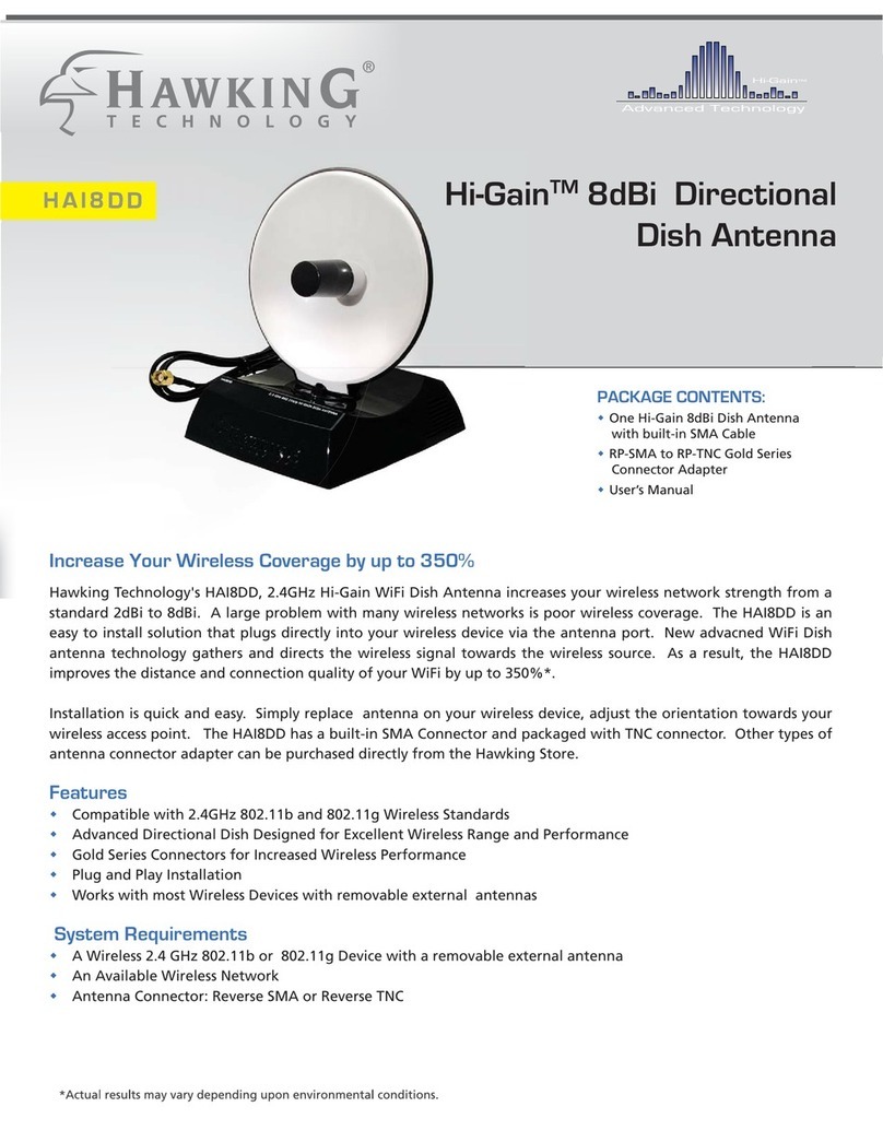
Hawking HAO14SDP User manual
Hawking
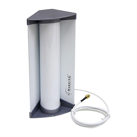
Hawking HAI8DD User manual
Hawking
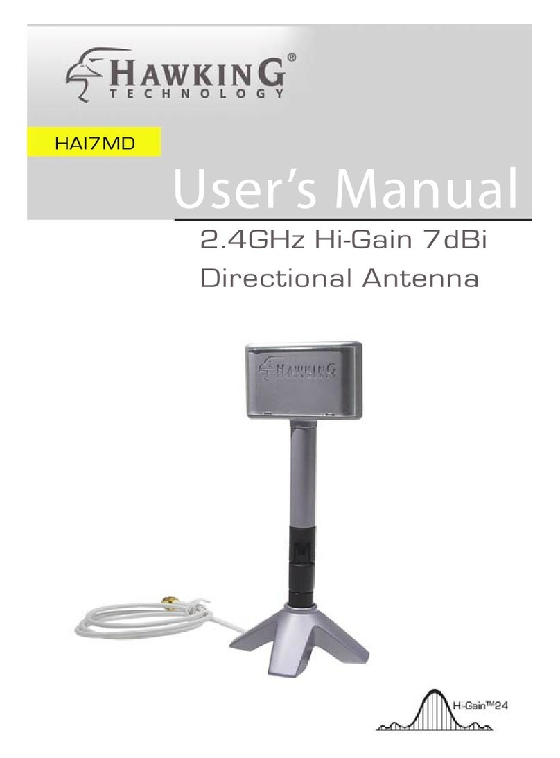
Hawking HAI15SC User manual
Hawking
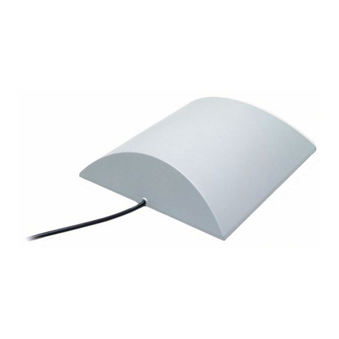
Hawking HAI7MD User manual
Hawking
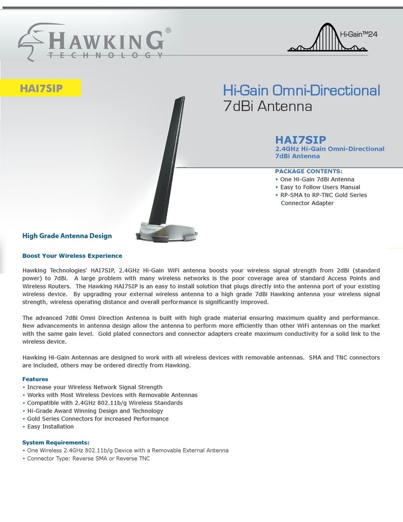
Hawking H-AO14SD User manual
Hawking
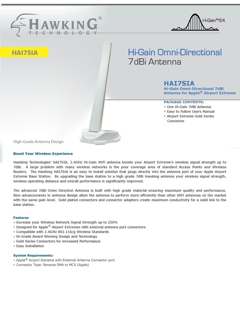
Hawking HAI7SIP User manual
Hawking
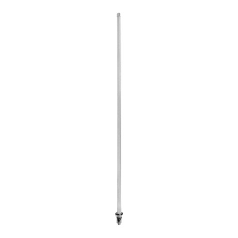
Hawking Hi-Gain HAO15SIP User manual
Hawking
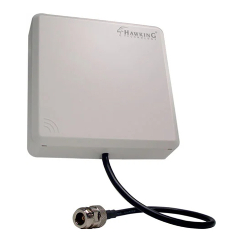
Hawking HAO9SDP User manual

Hawking
Hawking HAO9SDP User manual

Hawking
Hawking Hi-Gain HAO14MD User manual
Hawking
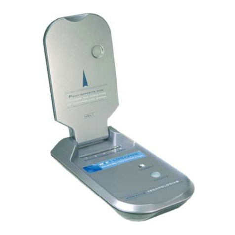
Hawking HWL1 User manual

Hawking
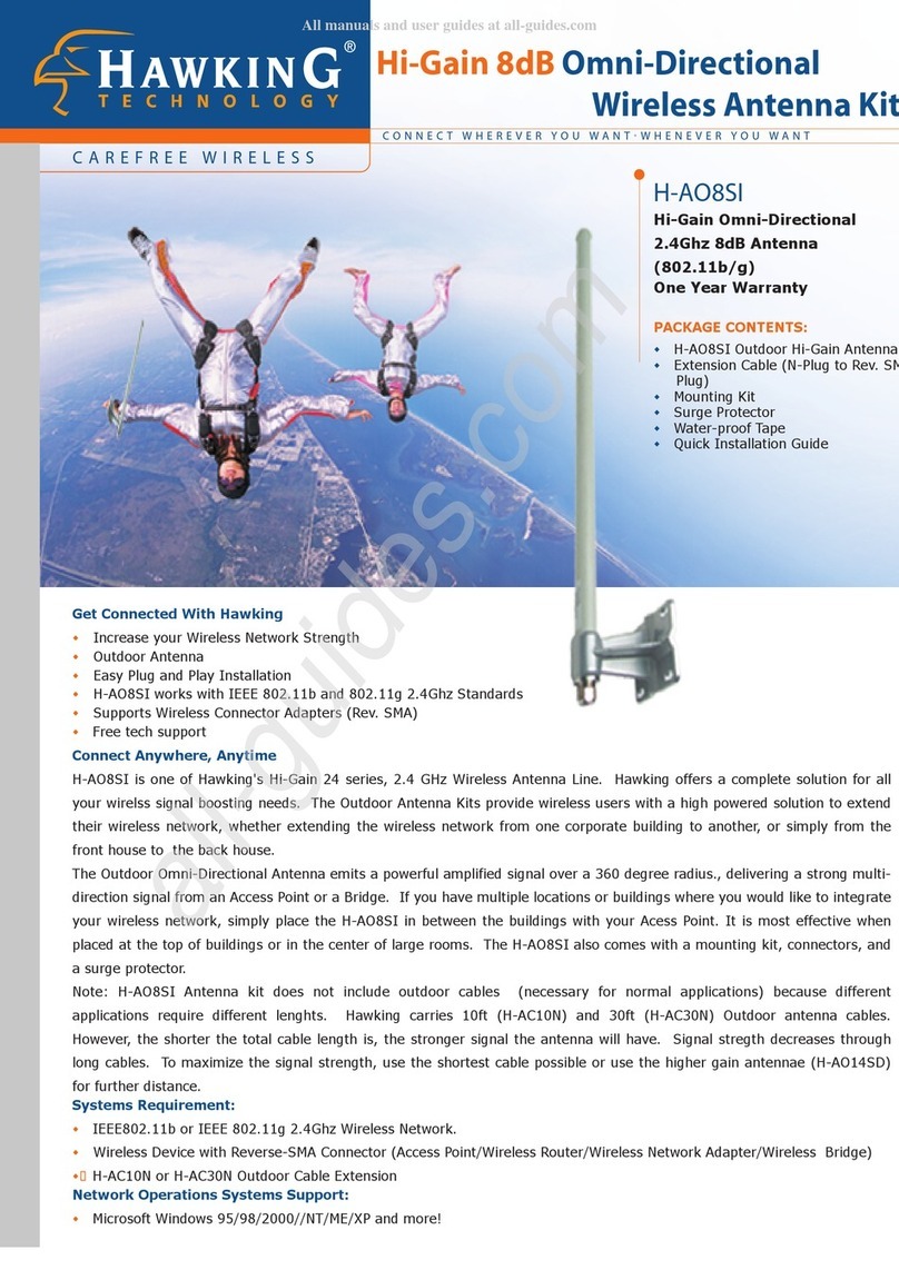
Hawking H-AO8SI User manual

Hawking
Hawking HAI7MD User manual

Hawking
Hawking HA12W User manual
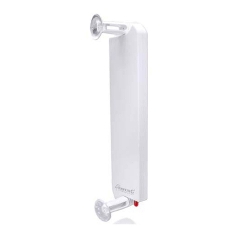
Hawking
Hawking HA12W User manual
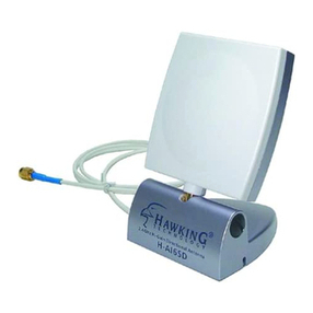
Hawking
Hawking HAI6SD User manual
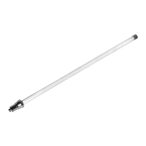
Hawking
Hawking Hi-Gain HAO15SIP User manual

Hawking
Hawking HA12W User manual
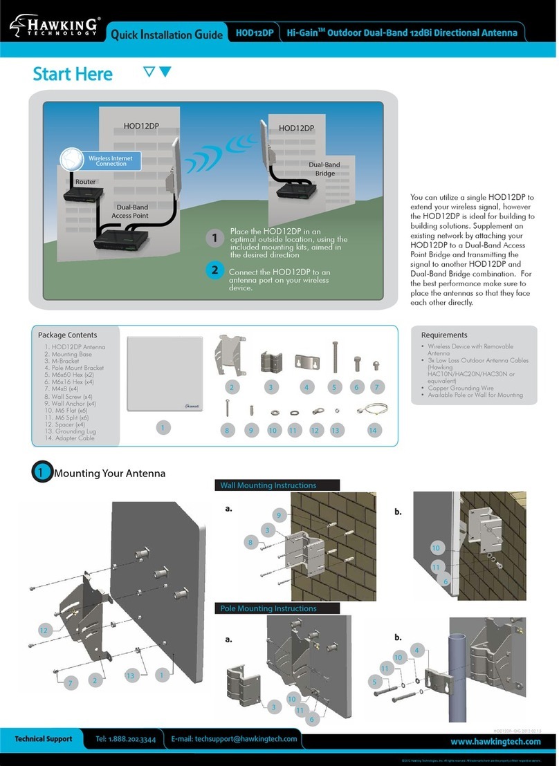
Hawking
Hawking HOD12DP User manual
Popular Antenna manuals by other brands

Alfa Network
Alfa Network APA-L01 Specifications

Naval
Naval PR-422CA Operation manual

Feig Electronic
Feig Electronic ID ISC.ANTH200/200 Series manual

TERK Technologies
TERK Technologies TV44 owner's manual

Directive Systems & Engineering
Directive Systems & Engineering DSE2324LYRMK quick start guide

HP
HP J8999A instructions

CommScope
CommScope CMAX-OMFX-43M-I53 Installation instruction

Ramsey Electronics
Ramsey Electronics DAP25 Kit assembly and instruction manual

COBHAM
COBHAM SAILOR 800 VSAT Replacement procedure

Trango Systems
Trango Systems AD900-9 Specification sheet

Steren
Steren ANT-100 user manual

IWCS
IWCS iriBelt II Quick start user guide
