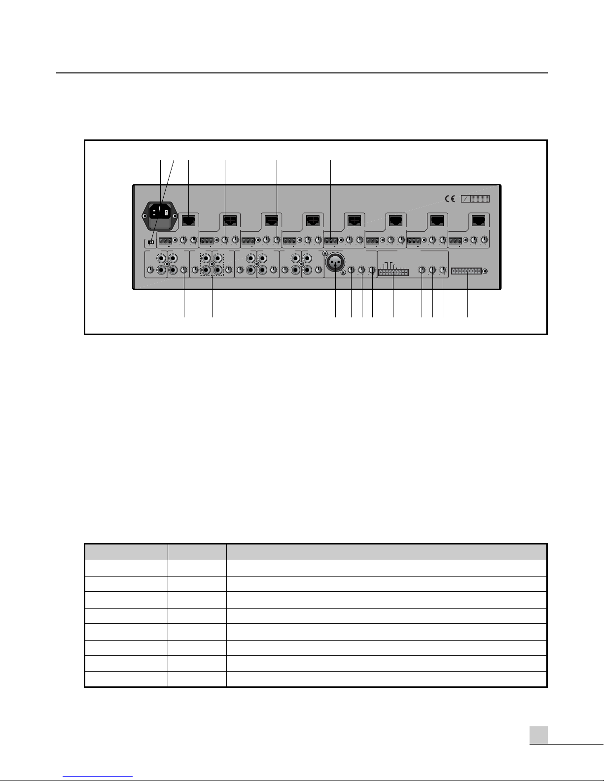
Inter-m PX-0288 User manual

PX-0288 Audio Matrix
PAGING MIC
REMOTE MIC
PAGING MIC
REMOTE MIC
PAGING MIC
REMOTE MIC
PAGING MIC
REMOTE MIC
PAGING MIC
REMOTE MIC
PAGING MIC
REMOTE MIC
PAGING MIC
REMOTE MIC
AUDIO MATRIX
POWER
PX
0288
MIN MAX
MONITOR
ALL TALK
ESC REC
56
34
12
ZONE SELECT
78
PAGING
MIN MAX
PAGING MIC
PGM
REMOTE CTRL
PGM SELECT
MIN MAX
REMOTE MIC
MIN MAX
ZONE 1
MIN MAX
PGM
REMOTE CTRL
PGM SELECT
MIN MAX
MIN MAX
ZONE 2
MIN MAX
PGM
REMOTE CTRL
PGM SELECT
MIN MAX
MIN MAX
ZONE 3
MIN MAX
PGM
REMOTE CTRL
PGM SELECT
MIN MAX
MIN MAX
ZONE 4
MIN MAX
PGM
REMOTE CTRL
PGM SELECT
MIN MAX
MIN MAX
ZONE 5
MIN MAX
PGM
REMOTE CTRL
PGM SELECT
MIN MAX
MIN MAX
ZONE 6
MIN MAX
PGM
REMOTE CTRL
PGM SELECT
MIN MAX
MIN MAX
ZONE 7
MIN MAX
PGM
REMOTE CTRL
PGM SELECT
MIN MAX
MIN MAX
ZONE 8
1
2
3
4
5
6
7
8
OFF
ON
PGM
PGM SELECT
B370031OC03OC03
0210

Contents
Contents
Welcome
Warning...............................................................................................................................1
Unpacking ............................................................................................................................2
Short Form Instructions...........................................................................................................2
Installation
Environment..........................................................................................................................3
Important Safety Instructions ...................................................................................................3
Description.............................................................................................................................4
Features..................................................................................................................................4
Accessories ...........................................................................................................................4
Panel
PX-0288 Front Panel..............................................................................................................5
PX-0288 Rear Panel ..............................................................................................................7
RM-88 Front Panel...............................................................................................................11
RM-88 Rear Panel ...............................................................................................................12
LM-88 / PS-88 Front Panel ..................................................................................................14
Applications.........................................................................................................................16
Connections .........................................................................................................................17
Operation
Operating the PX-0288........................................................................................................18
Operating the RM-88 ..........................................................................................................20
Operating the LM-88 / PS-88 ..............................................................................................20
Block Diagram ....................................................................................................................21
Specifications
PX-0288.............................................................................................................................22
RM-88................................................................................................................................23
LM-88/ PS-88.....................................................................................................................23
Service
Procedures..........................................................................................................................24
Schematic ...........................................................................................................................24
Parts List .............................................................................................................................24
Variations and Options .....................................................................................................24
Warranty..............................................................................................................................24

1
PX-0288
8x8 AUDIO MATRIX
Welcome
Welcome
A personal welcome to you from the management and employees of Inter-M
All of the co-workers here at Inter-M are dedicated to providing excellent products with inherently good value,
and we are delighted you have purchased one of our products.
We sincerely trust this product will provide years of satisfactory service, but if anything is not to your
complete satisfaction, we will endeavor to make things right.
Welcome to Inter-M, and thank you for becoming part of our worldwide extended family!
RISK OF ELECTRIC SHOCK
DO NOT OPEN
CAUTION
CAUTION: TO REDUCE THE RISK OF ELECTRIC SHOCK.
DO NOT REMOVE COVER (OR BACK).
NO USER-SERVICEABLE PARTS INSIDE.
REFER SERVICING TO QUALIFIED SERVICE PERSONNEL.
WARNING
To prevent fire or shock hazard, do not
expose the unit to rain or moisture.
*Do not install this equipment in a confined space such as a book case or similar unit.
*The apparatus shall not be exposed to dripping or splashing and no objects filled with liquids, such vases, shall be placed on the apparatus.
*Worded: “WARNING FOR YOUR PROTECTION PLEASE READ THE FOLLOWING-WATER AND MOISTURE: Unit should not be used
near water(e.g. near a bathtub, washbowl, kitchen sink, laundry tub, in a wet basement, or near a swimming pool, etc). Care should be taken
so than objects do not fall and liquids are not spilled into the enclosure through openings.”
This symbol is intended to alert the user to the
presence of uninsulated “dangerous voltage” within
the product’s enclosure that may be of suf-ficient
magnitude to constitute a risk of electric shock to
persons.
This symbol is intended to alert the user to the
presence of important operation and mainte-nance
(servicing) instructions in the literature accompanying
the appliance.
Caution: To prevent electric shock do not use this (polarized) plug with
an extension cord, receptacle or other outlet unless the blades
can be fully inserted to prevent blade expo-sure.
Attentions: Pour prévenir les chocs électriques ne pas utiliser cette
fiche polarisée avec un prolongateur, une prise de courant
on une autre sortie de courant, sauf si les lames peuvent
étre insérées à fond sans en laisser aucune partie à
découvert.

2PX-0288
8x8 AUDIO MATRIX
Unpacking
Please take a few minutes to read this manual to familiarize yourself with important information regarding
installation, product features, and operation.
As with most electronic devices, ORIGINAL PACKAGING (OR EQUAL) IS REQUIRED in the unlikely event that
the product needs to be returned for servicing.
Short Form Instructions
1. Do not connect the unit to the AC mains until some preliminary settings are completed. AC mains should only be switched
on later in this procedure. Ensure that the AC mains power and phantom power switches are in the OFF position.
2. Turn all GAIN level control knobs on the PX-0288 counter-clockwise to the "0" position.
3. Connect each zone OUTPUT of the PX-0288 to the corresponding zone of an amplified loudspeaker system.
4. Connect the LOCAL AUDIO SOURCES (tape deck, CD player, tuner, etc...) to the program inputs on the PX-
0288 and turn the input gain control knobs (on the rear panel) to half way between "0" and "10".
5. Connect the AC mains power cord to the PX-0288 and switch the AC mains power to the ON position. Switch
ON the PHANTOM POWER if condenser microphones will be used with this system.
6. Depress the program select (PGM SELECT) button located on the front panel until the illuminated number
displays the desired input channel number for the local audio source.
7. SLOWLY turn the ZONE gain control knobs clockwise to increase the level of the signal being sent to the
amplifier for the loudspeaker system until the desired level is reached. Obviously, if there is distortion,
feedback, or other cause for concern, reduce the signal level of the input or the output.
8. Connect one LM-88 or PS-88 to each of the ZONE CONTROL connectors as needed. Assign it the correct
zone address using the switches on the back. Connect a remote audio source or remote microphone to the
LM-88. Use the gain and program select controls on the remote instead of the ones located on the PX-0288.
The LM-88 and PS-88 have a higher priority that the PX-0288 and will override the gain and program select
settings on the PX-0288.
9. Connect one or more (maximum 4) RM-88 units to the remote mic input connector on the back of the PX-0288.
Connect a microphone to each RM-88. Select one or more zones using the selectors on the front of the RM-88.
Speak into the microphone and adjust the signal level (on the PX-0288, LM-88, or PS-88) accordingly.
10. Each of the eight output zones may source any one of the eight program inputs on the PX-0288. The LM-88
remote provides two additional inputs enabling its zone to have up to ten input sources.
11. Set the levels for each zone as desired by using the zone gain control on the PX-0288 or by using the gain
control on the LM-88 or PS-88, if so equipped.

3
PX-0288
8x8 AUDIO MATRIX
Installation
Installation
Environment
Never place this product in an environment which could alter its performance or reduce its service life. Such
environments usually include high levels of heat, dust, moisture, and vibration.
Important Safety Instructions
1. Read these instructions.
2. Keep these instructions.
3. Heed all warnings.
4. Follow all instructions.
5. Do not use this apparatus near water.
6. Clean only with dry cloth.
7. Do not block any ventilation openings. Install in accordance with the manufacturer’s instructions.
8. Do not install near any heat sources such as radiators, heat registers, stoves, or other apparatus (including
amplifiers) that produce heat.
9. Do not defeat the safety purpose of the polarized or grounding-type plug. A polarized plug has two blades
with one wider than the other. A grounding type plug has two blades and a third grounding prong. The wide
blade or the third prong are provided for your safety. If the provided plug does not fit into your outlet, consult
an electrician for replacement of the obsolete outlet.
10. Protect the power cord from being walked on or pinched particularly at plugs, convenience receptacles, and
the point where they exit from the apparatus.
11. Only use attachments/accessories specified by the manufacturer.
12. Use only with the cart, stand, tripod, bracket, or table specified by the manufacturer, or sold with the apparatus.
When a cart is used, use caution when moving the cart/apparatus combination to avoid injury from tip-over.
13. Unplug this apparatus during lightning storms or when unused for long periods of time.
14. Refer all servicing to qualified service personnel. Servicing is required when the
apparatus has been damaged in any way, such as power-supply cord or plug is
damaged, liquid has been spilled or objects have fallen into the apparatus, the
apparatus has been exposed to rain or moisture, does not operate normally, or has
been dropped.
- AVOID EXCESSIVE HEAT, HUMIDITY, DUST AND VIBRATION
Keep the unit away from locations where it is likely to be exposed to high temperatures or humidity-such as near radiators, stoves,
etc. Also avoid locations which are subject to excessive dust accumulation, or to vibration that could cause mechanical damage.
- AVOID PHYSICAL SHOCKS
Strong physical shocks to the unit may cause damage. Handle the unit with care.
- DO NOT OPEN THE CASE OR ATTEMPT REPAIRS OR MODIFICATIONS YOURSELF
This product contains no user-serviceable parts. Refer all maintenance to qualified Inter-M service personnel.
Opening the case and/or tampering with internal circuitry voids the warranty.
- ALWAYS POWER OFF BEFORE MAKING CONNECTIONS
Always turn the AC mains OFF before connecting or disconnecting cables. This is important to prevent damage to
the unit itself as well as other connected equipment.
- HANDLE CABLES CAREFULLY
Always plug and unplug cables (including the AC mains power cord) by gripping the connector, not the cord.
- CLEAN WITH A SOFT DRY CLOTH
Never use solvents such as benzine or paint thinner to clean the unit. Wipe clean with a soft, dry cloth.
S3125A
S3125A

4PX-0288
8x8 AUDIO MATRIX
Description
Description
The PX-0288 and related components provides the latest technology combined with ease of operation to
create a system which offers enormous capability and flexibility. Local audio sources may be sent to any
combination of up to eight remote zones and do so with either local or remote control.
This type of flexibility makes this product ideal for any type of multi-zone system including hotels, airports,
casinos, hospitals, conference centers, and restaurants.
A wide assortment of remote devices insures that the right amount of control is located in the correct
locations throughout a facility.
Features
Features
- Eight local music sources may be received at one time.
- Local and remote paging capabilities with priority override.
- Eight output zones each capable being controlled by a remote station.
- Monitor speaker built into the local device.
- Phantom Power for use with Condenser microphones.
Accessories
An AC mains power cord is provided with the PX-0288. No other accessories are provided with these
products.

5
PX-0288
8x8 AUDIO MATRIX
PX-0288 Front Panel
PX-0288 Front Panel
1. MONITOR SPEAKER
This built in monitor loudspeaker allows for any of the 8 input sources to be selected and auditioned.
2. INPUT CHANNEL SELECTOR SWITCH
This selects which input will supply each zone (or which zone will supply the monitor loudspeaker). A
different input will be selected with each press of the button.
3. INPUT SELECTION DISPLAY
This displays the number of the input channel which has been selected for each zone (or which zone has
been selected for the monitor loudspeaker).
4. REMOTE MIC STATION LEVEL CONTROL
This determines the level of the signal originating from the remote microphone station for each channel. Turned
fully counterclockwise is "MINIMUM" or no signal, and turned fully clockwise is "MAXIMUM" or full signal.
5. PAGING MIC LEVEL CONTROL
This adjusts the signal level originating from the paging microphone for each channel. Turned fully
counterclockwise is "MINIMUM" or no signal, and turned fully right is "MAXIMUM" or full signal.
6. INDIVIDUAL ZONE PAGING SELECTOR SWITCH
Depressing this switch determines which zone(s) the paging microphone signal will be sent to. The switch will
illuminate to indicate that the selected zone will receive the paging signal.
7. LABEL AREA
This area is provided to allow each input source to be labeled according to the needs of the installation.
PAGING MIC
REMOTE MIC
PAGING MIC
REMOTE MIC
PAGING MIC
REMOTE MIC
PAGING MIC
REMOTE MIC
PAGING MIC
REMOTE MIC
PAGING MIC
REMOTE MIC
PAGING MIC
REMOTE MIC
AUDIO MATRIX
POWER
PX
0288
PGM
PGM SELECT
MIN MAX
MONITOR
ALL TALK
56
34
12
ZONE SELECT
78
PAGING
MIN MAX
PAGING MIC
PGM
REMOTE CTRL
PGM SELECT
MIN MAX
REMOTE MIC
MIN MAX
ZONE 1
MIN MAX
PGM
REMOTE CTRL
PGM SELECT
MIN MAX
MIN MAX
ZONE 2
MIN MAX
PGM
REMOTE CTRL
PGM SELECT
MIN MAX
MIN MAX
ZONE 3
MIN MAX
PGM
REMOTE CTRL
PGM SELECT
MIN MAX
MIN MAX
ZONE 4
MIN MAX
PGM
REMOTE CTRL
PGM SELECT
MIN MAX
MIN MAX
ZONE 5
MIN MAX
PGM
REMOTE CTRL
PGM SELECT
MIN MAX
MIN MAX
ZONE 6
MIN MAX
PGM
REMOTE CTRL
PGM SELECT
MIN MAX
MIN MAX
ZONE 7
MIN MAX
PGM
REMOTE CTRL
PGM SELECT
MIN MAX
MIN MAX
ZONE 8
1
2
3
4
5
6
7
8
OFF
ON
ESC REC
325
810
914
14
6 7
1211 13

6PX-0288
8x8 AUDIO MATRIX
8. MONITOR OUTPUT CONTROL KNOB
This determines the level of the monitor loudspeaker. Turned fully counterclockwise is "MINIMUM" or no
output, and turned fully clockwise is "MAXIMUM" or full output.
9. REMOTE CONTROLLER ENABLE/DISABLE SWITCH
This switch is used to ENABLE/DISABLE (ON/OFF) the remote controllers (LM-88/PS-88) that are connected
to each zone. The switch will illuminate to indicate that the remote is ENABLED and has control of the settings
of the zone.
When a remote is ENABLED the initial signal level will be equal to the level determined by the level control on
the PX-0288. Each time the remote is DISABLED the signal level for the zone will return to the level
determined by the level control on the PX-0288 A dot ( 1.) will appear next to the source selected in the
display of the LM-88/PS-88 remote confirming that the remote is enabled. Remotes are disabled (OFF)
during an Emergency Announcement.
10. BGM SOURCE OUTPUT CONTROL KNOB
This determines the level of the output of each individual channel. Turned fully counterclockwise is
"MINIMUM" or no output and turned fully clockwise is "MAXIMUM" or full output.
11. LABEL AREA
This area is provided to allow each zone to be labeled according to the needs of the installation.
12. ALL/ESC
Depressing this button before the Talk button has been depressed will send the paging microphone signal to
all zones. Every zone select indicator will illuminate confirming that all of the zones have been selected to
receive the paging signal.
Depressing this button after the Talk button has been depressed one time will cause the unit to escape (exit)
from the RECORD READY mode.
13. TALK/REC
After a Page Zone has been selected, this button switches the signal from the paging microphone ON/OFF.
The letter “P” will be displayed for each corresponding zone indicating that the zone is receiving a Paging
signal.
When no zones are selected for paging this button is used for recording Emergency Announcements.
Depressing the button one time will cause the unit to enter RECORD READY mode. This mode is confirmed by
displaying “-RECORD-“on the alphanumeric displays. Depressing and holding the button a second time will
cause the unit to enter RECORD mode. This mode is confirmed by clockwise rotation of the first and last digits
of the “-RECORD-“ display. Depressing the button a third time will end the recording.
14. POWER SWITCH
This switch turns the AC mains ON/OFF. When in the ON position, the switch will illuminate.

7
PX-0288
8x8 AUDIO MATRIX
PX-0288 Rear Panel
PX-0288 Rear Panel
1. AC MAINS POWER INPUT
This is the AC MAINS input receptacle which accepts the detachable AC power cable. Connect only to an
appropriate AC mains power source.
2. PHANTOM POWER SWITCH
When this switch is in the ON position, Phantom Power(DC +24V) will be provided between pin 2 and pin 3
of the PAGING MIC INPUT XLR-type jack. If you do not use microphones that require phantom power, be
sure this switch is in the OFF position.
3. REMOTE CONTROL CONNECTOR
One remote control (either the LM-88 or the PS-88) may be connected to each output zone. Each remote will
need to be given an address (or identity) which is accomplished via DIP switches on the remote. Each remote
must be addressed according to the zone it controls. Do not give the same address to more than one remote.
-PIN Legend (RJ-45, UTP Cat5)
PHANTOM
10
010
0
www.inter-m.com
PGM 1
L
R
PGM 2
L
R
PGM 3
L
R
PGM 4
L
R
PGM 5
L
R
PGM 6
L
R
PGM 7
L
R
PGM 8
L
R
LEVEL LEVELLEVELLEVELLEVELLEVEL LEVEL LEVEL
PAGING MIC IN
LEVEL TREBLE BASS LEVEL
REMOTE MIC IN
SN
ON OFF
TREBLE
OUTPUT BASS TREBLE
OUTPUT BASSTREBLE
OUTPUT BASSTREBLE
OUTPUT
CONTROL
BASS TREBLE
OUTPUT BASS TREBLE
OUTPUT BASS TREBLE
OUTPUT BASS TREBLE
OUTPUT BASS
PHANTOM
CONTROL CONTROL CONTROL CONTROL CONTROL CONTROL CONTROL
ZONE 1 ZONE 7 ZONE 8ZONE 2 ZONE 3 ZONE 4 ZONE 5 ZONE 6
FIRE ALARM
CONTACT CLOSURE
5678GND4321
12
12 1212
TREBLE BASS
1212 1212
1212 12121212 12121212 12121212 12121212 12121212 12121212 12121212 1212
10 10 10 10 10 10 10 10
0000000 0
+
G
+
G
+
G
+
G
+
G
+
G
+
G
+
G
CONTROL
A-GND Rx-Rx+Tx-Tx+
AUD-
AUD+ DC 24V
D-GND
32
7
1 64 5
8 101112 1415169 13 17
PIN Number
1
2
3
4
5
6
7
8
PIN NAME Functions
Rx- RS-422 Negative Receive
Rx+ RS-422 Positive Receive
Tx- RS-422 Negative Transmit
Tx+ RS-422 Positive Transmit
D-GND Digital Ground
DC Output Power Supply
Audio+ Balanced Audio Hot
Audio- Balanced Audio Cold

8PX-0288
8x8 AUDIO MATRIX
-Remote Address Setup Legend
4. TREBLE CONTROL
This controls the high frequency signal level for the individual ZONE. The center position is flat (normal)
offering no boost or cut. Turning counterclockwise will reduce the high frequency level, turning clockwise will
increase the high frequency. The maximum range of adjustment is ±12dB.
5. BASS CONTROL
This controls the amount of the low frequency on the individual ZONE. The center position is flat (normal)
offering no boost or cut. Turning counterclockwise will reduce the low frequency level, turning clockwise will
increase the low frequency. The maximum range of adjustment is ±12dB.
6. OUTPUT CONNECTOR
Each zone is equipped with one 3-conductor balanced line level output. The output can be connected to a
recorder, an amplified speaker system, or other destination as required by the installation.
7. GAIN
This controls the input signal level for each channel. Turned fully counterclockwise is "MINIMUM" or no
signal, and turned fully clockwise is "MAXIMUM" or full signal.
8. PGM INPUT JACKS
These 2-conductor unbalanced RCA-type jacks are available to connect Line level sources such as tape decks,
CD players, and tuners. The Left and Right signals are combined internally and are then available as a mono
source for any of the eight output channels.
9. PAGING MIC INPUT/RECORD
This microphone input will accept either a condenser or dynamic paging microphone which can be routed to
any of the 8 output zones. This input is also used to record an Emergency Announcement on the internal
Digital Voice File.
10. PAGING MIC INPUT LEVEL CONTROL
This controls the input signal level of the paging microphone. Turned fully counterclockwise is "MINIMUM" or
no signal, and turned fully clockwise is "MAXIMUM" or full signal.
Output Zone
Zone 1
Zone 2
Zone 3
Zone 4
Zone 5
Zone 6
Zone 7
Zone 8
PIN No. 1 PIN No. 2 PIN No. 3
Off Off Off
On Off Off
Off On Off
On On Off
Off Off On
On Off On
Off On On
On On On

9
PX-0288
8x8 AUDIO MATRIX
11. TREBLE CONTROL
This controls the amount of the high frequency on the PAGING MICROPHONE. The center position is flat
(normal) offering no boost or cut. Turning counterclockwise will reduce the high frequency level, turning
clockwise will increase the high frequency. The maximum range of adjustment is ±12dB.
12. BASS CONTROL
This controls the amount of the low frequency on the PAGING MICROPHONE. The center position is flat
(normal) offering no boost or cut. Turning counterclockwise will reduce the low frequency level, turning
clockwise will increase the low frequency. The maximum range of adjustment is ±12dB.
13. REMOTE MIC STATION CONNECTOR
This is the input connector for one or more remote mic stations. Multiple stations are connected by
connecting one to another and to this input.
-Remote Mic Station Connector Pin legend
14. REMOTE MIC INPUT LEVEL CONTROL
This controls the level of the input signal of a remote mic from a remote mic station. Turned fully
counterclockwise is "MINIMUM" or no signal and turned fully clockwise is "MAXIMUM" or full signal.
15. TREBLE CONTROL
This controls the amount of the high frequency on the REMOTE MICROPHONE. The center position is flat
(normal) offering no boost or cut. Turning counterclockwise will reduce the high frequency level, turning
clockwise will increase the high frequency. The maximum range of adjustment is ±12dB.
16. BASS CONTROL
This controls the amount of the low frequency on the REMOTE MICROPHONE. The center position is flat
(normal) offering no boost or cut. Turning counterclockwise will reduce the low frequency level, turning
clockwise will increase the low frequency. The maximum range of adjustment is ±12dB.
PIN Number
1
2
3
4
5
6
7
8
9
PIN NAME Functions
Rx- RS-422 Negative Receive
Rx+ RS-422 Positive Receive
Tx- RS-422 Negative Transmit
Tx+ RS-422 Positive Transmit
D-GND Digital Ground
DC Output Power Supply
Audio+ Balanced Audio Hot
Audio- Balanced Audio Cold
A-GND Analog Ground

10 PX-0288
8x8 AUDIO MATRIX
17. FIRE ALARM CONTACT CLOSURE
Contact closures are provided for each of the eight zones. Emergency messages can be sent to any zone
preset to receive such messages.
-Remote Address Setup Legend
PIN Number
1
2
3
4
5
6
7
8
9
PIN NAME Functions
D-GND Shared ground port
Zone 8 CC Contact point input port for Zone 8
Zone 7 CC Contact point input port for Zone 7
Zone 6 CC Contact point input port for Zone 6
Zone 5 CC Contact point input port for Zone 5
Zone 4 CC Contact point input port for Zone 4
Zone 3 CC Contact point input port for Zone 3
Zone 2 CC Contact point input port for Zone 2
Zone 1 CC Contact point input port for Zone 1

11
RM-88
REMOTE MIC STATION
RM-88 Front Panel
RM-88 Front Panel
1. REMOTE MIC INPUT
This allows one microphone to be connected to the RM-88.
2. AUDIO LEVEL METER
It displays the audio level of input or output.
3. BUSY INDICATOR
This indicates which of the RM-88 are in use at the moment. There are no priorities given to the remotes so
the first to make signal is the only one active at any time.
4. POWER INDICATOR
This confirms that the remote is connected and has power applied.
5. ALL BUTTON
When depressed this switch selects all eight zones to receive the signal from this station.
6. TALK BUTTON
This push-to-talk button switches "on" or "off" the microphone input with each depression of the switch. Each
corresponding zone will display an “A” indicating that the zone is receiving an announcement.
7. ZONE SELECTOR
This button switches "on" or "off" the corresponding zone with each depression of the switch. Multiple zones
may be selected at one time.
8. LABEL LOCATION
This allows the option of marking or labeling each zone for easy identification.
5
6
8
4
1
7
2
3
POWER
MIC
1234
BUSY
ALL
TALK
ZONE 1 ZONE 2 ZONE 3 ZONE 4
ZONE 5 ZONE 6 ZONE 7 ZONE 8
RM 88
REMOTE MIC STATION
-18
LEVEL
-15 -12 -9 -6 -3 0 +3 +6 +9

12 RM-88
REMOTE MIC STATION
RM-88 Rear Panel
RM-88 Rear Panel
1. CONTROL CONNECTOR
This connector links to PX-0288 and to other RM-88 using 9 conductor (8 plus shield).
-Connector Pin Legend (using 9 conductor (8 plus shield)
2. OUTPUT CONTROL
This determines the output signal level of the RM-88 signal being sent to the PX-0288.
3. MONITOR CONTROL
It determines the volume level of the internal monitoring speaker.
1234
4321 5 6 7 8
100100
CHIME
CONTROL MONITOROUTPUT
NOT USED ADDRESS
www.inter-m.com
SN
MODEL NO. RM-88
REMOTE MIC STATION
0210
OC03
D-GND Rx
Tx
AUD
AUD
A-GND
DC 24V Rx
Tx
PIN Number
1
2
3
4
5
6
7
8
9
PIN NAME Functions
Tx- RS-422 Positive Transmit
Tx+ RS-422 Positive Transmit
Rx- RS-422 Negative Receive
Rx+ RS-422 Positive Receive
D-GND Digital Ground
DC Input Power Supply
Audio+ Balanced Audio Hot
Audio- Balanced Audio Cold
A-GND Analog Ground

13
RM-88
REMOTE MIC STATION
4. ADDRESS AND CHIME SWITCHES
The position of these switches will determine the ADDRESS assigned to the remote and the status of the
CHIME.
-Address and Chime Switch Position Legend
Move switch #4 to the "on" position to assign address #1 to the remote. Address #1 will correspond to the
#1 BUSY indicator on the front of the remote. Each remote requires a unique address so the next remote
should be assigned address #2. This process may be repeated for up to a maximum of four remotes since
there are four addresses. It is important that the same address is not assigned to more than one remote.
A CHIME tone may be used to precede a Microphone Paging. Move switch #8 to the "on" position to enable
the CHIME feature and the "off" position to disable the CHIME.
Switch Number
1
2
3
4
5
6
7
8
Functions
Not used (Used only for Program)
Remote Mic Station #1
Remote Mic Station #2
Remote Mic Station #3
Remote Mic Station #4
On : Chime Enable / Off : Chime Disable

14 LM-88/PS-88
REMOTE CONTROLLER WITH AUDIO INPUT
LM-88/PS-88 Front Panel
Each Remote requires an exclusive address that is not shared with any other remote. Using the legend below
assign each remote a zone address that matches the assigned output zone the remote is connected to on the rear
of the PX-0288. Do not assign the same address to more than one remote.
-PIN Legend (RJ-45, UTP Cat5)
1
2
3
4
5
6
7
8
12
3
LEVEL
LM 88
L
R
MIC
SELECT
PGM
LEVEL
PS 88
SELECT
PGM
LINE
1
2
3
4
5
6
7
8
VOLUMEVOLUME
100
10010
MAXMIN
MAXMIN
1
67
2543
8
Output Zone
Zone 1
Zone 2
Zone 3
Zone 4
Zone 5
Zone 6
Zone 7
Zone 8
SWITCH No. 1 SWITCH No. 2 SWITCH No. 3
Off Off Off
On Off Off
Off On Off
On On Off
Off Off On
On Off On
Off On On
On On On
PIN Number
1
2
3
4
5
6
7
8
PIN NAME Functions
Tx- RS-422 Negative Transmit
Tx+ RS-422 Positive Transmit
Rx- RS-422 Negative Receive
Rx+ RS-422 Positive Receive
D-GND Digital Ground
DC Input Power Supply
Audio+ Balanced Audio Hot
Audio- Balanced Audio Cold

15
LM-88/PS-88
REMOTE CONTROLLER WITH AUDIO INPUT
1. REMOTE AUDIO SOURCE STEREO INPUT
These 2-conductor unbalanced RCA type jacks are available to connect Line level sources such as tape decks, CD
players, and tuners. The Left and Right signals are combined internally and are then available as a mono source
to the system. Signal applied to these inputs will mute the local input signal from the PX-0288.
2. REMOTE BGM GAIN CONTROL
This controls the level of the REMOTE AUDIO SOURCE STEREO INPUT signal. Turned fully counterclockwise
is "MINIMUM" or no signal and turned fully clockwise is "MAXIMUM" or full signal.
3. INPUT SELECTION DISPLAY
This displays the number of the input channel which has been selected for the zone.
4. LABEL AREA
This area is provided to allow each local audio source to be labeled according to the needs of each
installation.
5. INPUT CHANNEL SELECTOR SWITCH
This selects which input will supply each zone. A different input will be selected with each press of the button.
6. REMOTE MICROPHONE INPUT
This 3-conductor balanced XLR type jack accepts a balanced microphone for use with or without the stereo
input. Signal applied to this input will mute the local input signal from the PX-0288.
7. MIC GAIN CONTROL
This controls the level of the REMOTE MICROPHONE INPUT signal. Turned fully counterclockwise is
"MINIMUM" or no signal and turned fully clockwise is "MAXIMUM" or full signal.
8. OUTPUT BGM GAIN CONTROL
This controls the volume level of the zone for which the remote has been assigned. Turning the knob
counterclockwise will reduce the level of the signal and turning it fully clockwise will increase the level of the
signal. This knob will turn continuously in either direction. Continue to turn the knob in the desired direction
until the desired level is reached. Because this is a continuously turning knob the level indicator could be
misleading at times by pointing to “minimum” when there is actually substantial level.
Remote Mic Station Fire Alarm Paging Enable
RFP.(DOT)

16 PX-0288
8x8 AUDIO MATRIX
Applications
Applications
PHANTOM
10
010
0
www.inter-m.com
PGM 1
L
R
PGM 2
L
R
PGM 3
L
R
PGM 4
L
R
PGM 5
L
R
PGM 6
L
R
PGM 7
L
R
PGM 8
L
R
LEVEL LEVELLEVELLEVELLEVELLEVEL LEVEL LEVEL
PAG IN G MIC I N
LEVEL TREBLE BASS LEVEL
REMOTE MIC IN
SN
ON OFF
TREBLE
OUTPUT BASS TREBLE
OUTPUT BASSTREBLE
OUTPUT BASSTREBLE
OUTPUT
CONTROL
BASS TREBLE
OUTPUT BASS TREBLE
OUTPUT BASS TREBLE
OUTPUT BASS TREBLE
OUTPUT BASS
PHANTOM
CONTROL CONTROL CONTROL CONTROL CONTROL CONTROL CONTROL
ZONE 1 ZONE 7 ZONE 8ZONE 2 ZONE 3 ZONE 4 ZONE 5 ZONE 6
FIRE ALARM
CONTACT CLOSURE
5678GND4321
1212 1212
TREBLE BASS
1212 1212
1212 12121212 12121212 12121212 12121212 12121212 12121212 12121212 1212
10 10 10 10 10 10 10 10
0000000 0
+
G
+
G
+
G
+
G
+
G
+
G
+
G
+
G
CONTROL
A-GND Rx-Rx+Tx-Tx+
AUD-
AUD+ DC 24V
D-GND
LM-88
PGM
SELECT
GAIN
R
L
MIC
1
2
3
4
5
6
7
8
PS-88
PGM
SELECT
1
2
3
4
5
6
7
8
LINE
0
GAIN
8
0
GAIN
8
0
8
GAIN
0
8
PS-88
PGM
SELECT
1
2
3
4
5
6
7
8
GAIN
0
8
12
3
ON
ON
Remote BGM
MIC
Paging MIC
Local BGM
Address "000" Address "001" Address "111"
RM-88 #4
POWER
MIC
1234
BUSY
ALL
TALK
ZONE 1 ZONE 2 ZONE 3 ZONE 4
ZONE 5 ZONE 6 ZONE 7 ZONE 8
RM
88
REMOTE MIC STATION
-18
LEVEL
-15 -12 -9 -6 -3 0 +3 +6 +9
RM-88 #3
POWER
MIC
1234
BUSY
ALL
TALK
ZONE 1 ZONE 2 ZONE 3 ZONE 4
ZONE 5 ZONE 6 ZONE 7 ZONE 8
RM
88
REMOTE MIC STATION
-18
LEVEL
-15 -12 -9 -6 -3 0 +3 +6 +9
RM-88 #2
POWER
MIC
1234
BUSY
ALL
TALK
ZONE 1 ZONE 2 ZONE 3 ZONE 4
ZONE 5 ZONE 6 ZONE 7 ZONE 8
RM
88
REMOTE MIC STATION
-18
LEVEL
-15 -12 -9 -6 -3 0 +3 +6 +9
RM-88 #1
POWER
MIC
1234
BUSY
ALL
TALK
ZONE 1 ZONE 2 ZONE 3 ZONE 4
ZONE 5 ZONE 6 ZONE 7 ZONE 8
RM
88
REMOTE MIC STATION
-18
LEVEL
-15 -12 -9 -6 -30+3+6 +9
PX-0288
Maximum 300m(UTP)
Maximum 300m(UTP)
Maximum 300m(UTP)
Fire Alarm Contact

17
PX-0288
8x8 AUDIO MATRIX
Connections
Connections
RL
DC INPUT
24V UNBAL / 75ΩLOOP
ANT.
LR
STEREO
MONO(BAL)MONO(BAL)
VARIABLEFIXED
SNwww.inter-m.com
OUTPUT ANT
RESET
FM AM
www.inter-m.com
~AC INPUT
230V 50Hz, 12W
OUTPUT
R
L
GND
( )
www.inter-m.com
PHANTOM
10
010
0
www.inter-m.com
PGM 1
L
R
PGM 2
L
R
PGM 3
L
R
PGM 4
L
R
PGM 5
L
R
PGM 6
L
R
PGM 7
L
R
PGM 8
L
R
LEVEL LEVELLEVELLEVELLEVELLEVEL LEVEL LEVEL
PAGING MIC IN
LEVEL TREBLE BASS LEVEL
REMOTE MIC IN
SN
ON OFF
TREBLE
OUTPUT BASS TREBLE
OUTPUT BASETREBLE
OUTPUT BASSTREBLE
OUTPUT
CONTROL
BASS TREBLE
OUTPUT BASS TREBLE
OUTPUT BASS TREBLE
OUTPUT BASS TREBLE
OUTPUT BASS
PHANTOM
CONTROL CONTROL CONTROL CONTROL CONTROL CONTROL CONTROL
ZONE 1 ZONE 7 ZONE 8ZONE 2 ZONE 3 ZONE 4 ZONE 5 ZONE 6
FIRE ALARM
CONTACT CLOSURE
5678GND4321
12
12 1212
TREBLE BASS
1212 1212
1212 12121212 12121212 12121212 12121212 12121212 12121212 12121212 1212
10 10 10 10 10 10 10 10
0000000 0
+
G
+
G
+
G
+
G
+
G
+
G
+
G
+
G
CONTROL
A-GND Rx-Rx+Tx-Tx+
AUD-
AUD+ DC24V
D-GND
PUSH PUSHPUSH PUSH
PUSH PUSHPUSH PUSH
PX-0288
CDC-2050
PC-9335S
PT-9107S
TP-9231
QD-4480
QD-4480
OT-4480
Zone1 Zone2 Zone3 Zone4
HIGH IMPEDENCE Zone5 Zone6 Zone7 Zone8
LOW IMPEDENCE

18 PX-0288
8x8 AUDIO MATRIX
Operation
Operation
The following explanation will instruct the user on how to operate the controls and make adjustments. Experience
and patience are required in most cases to fully appreciate the capabilities of the system.
Begin by reading the "Short Form" instructions. The Short Form section is provided for operators that do not
require extensive instructions. Novices will find the operation information most helpful. The information it
provides will be the foundation for building operating skills and techniques that can result in proficient console
operation.
These instructions are written in operational order and do not necessarily follow the physical layout.
Operating the PX-0288
1. Program (PGM) Inputs and Zone Outputs
-Connect an audio source (tape deck, CD, etc. to input channel #1 on the rear panel of the PX-0288.
-Depress the zone #1 PGM SELECT button (located on the front panel) until the display indicates input #1.
Note: This will also cause the display of the LM-88 or the PS-88 remote to read input #1 if connected.
-Adjust the volume and the tone by adjusting the Input and Output gain and the Tone Control on the PX-0288.
-Any input may be selected by any zone. Do not connect more than one audio source per input channel.
2. Monitor Speaker
-Select one of the zones that is receiving signal from an input using the MONITOR ZONE select button
-Adjust the MONITOR GAIN until the desired level is heard from the internal monitor loudspeaker.
3. Paging Mic
-Connect a Paging Microphone to the PAGING MIC connector on the rear of the PX-0288.
-Select one or more zones within the PAGING section of the front of the PX-0288.
-When the TALK switch is depressed, the Pre Announce Chime will be sent and the system will enter into
broadcasting Ready state. The displays of the selected zones will show the letter "P" to confirm that the system
is ready for a paging.
-Announce into the paging microphone the information to be paged.
-Once the paging is completed, depress the TALK button again to restore the previous settings.
4. Remote Control
-Connect a LM-88 or PS-88 to the desired zone CONTROL connection on the rear of the PX-0288 and assign
the appropriate address to the remote.
-Press the Remote Enable/Disable switch on the front of the PX-0288 to enable the Remote Controller for a
particular zone. The enable status will be confirmed by illuminating the switch.
-Remote sources (sources connected to the remote) have priority over local sources (sources connected to the
PX-0288) and result in the local source being muted while a remote source is enabled and operating.
-Enabling the Remote will also prevent the Input Selector Switch and the zone Gain on the PX-0288 from operating.
Changes to the Input Selector on the Remote will simultaneously change the display on the PX-0288.
Table of contents
Other Inter-m Music Mixer manuals

Inter-m
Inter-m CMX-1264 User manual

Inter-m
Inter-m IMX-824 User manual

Inter-m
Inter-m IMX-824 User manual

Inter-m
Inter-m CA-8320 User manual

Inter-m
Inter-m CMX-1642 User manual

Inter-m
Inter-m MX-1243 User manual

Inter-m
Inter-m MX-1243 User manual

Inter-m
Inter-m IMX-416 User manual

Inter-m
Inter-m LM-6414 User manual

Inter-m
Inter-m MX-1424 User manual

Inter-m
Inter-m MX-1646D User manual

Inter-m
Inter-m CMX-842 User manual

Inter-m
Inter-m CA-6220 User manual

Inter-m
Inter-m MX-1646 User manual

Inter-m
Inter-m LM-9228 User manual

Inter-m
Inter-m CA-8320 User manual

Inter-m
Inter-m CA-5115D User manual

Inter-m
Inter-m MX-1646 User manual

Inter-m
Inter-m MX-1242A User manual

Inter-m
Inter-m RMX-1426 User manual