PSG DM-1608 Series User manual

DM-1608 Series User Manual
Catalog
1. Introduction..............................................................................................................................3
2. Parameters................................................................................................................................4
3. Packing List ...............................................................................................................................5
4. Interface/key Description.........................................................................................................5
4.1. Front Panel:...............................................................................................................5
4.2. Back Panel:................................................................................................................6
5. Instructions for Use ..................................................................................................................6
5.1. Software and Documentation Download.....................................................................6
5.2. PC Software Login.........................................................................................................7
5.3. Main Interface..............................................................................................................7
5.4. Input Channel...............................................................................................................8
5.4.1. Overview..........................................................................................................8
5.4.2. Config...............................................................................................................9
5.4.3. EQ...................................................................................................................10
5.4.4. Comp..............................................................................................................11
5.4.5. Gate ...............................................................................................................12
5.4.6. AUX Sends......................................................................................................13
5.4.7. FX Sends.........................................................................................................13
5.5. Output Channels ........................................................................................................14
5.5.1. Overview........................................................................................................14
5.5.2. config .............................................................................................................15
5.5.3. PEQ.................................................................................................................15
5.5.4. GEQ................................................................................................................16
5.5.5. comp/Limiter .................................................................................................17
5.5.6. Anti-Feedback................................................................................................18
5.6. FX Effects Channels.....................................................................................................19
5.6.1. Overview........................................................................................................19
5.6.2. config .............................................................................................................20
5.6.3. EQ...................................................................................................................20
5.6.4. AUX Sends......................................................................................................21
5.6.5. Effect Type .....................................................................................................22
5.7. Playback/Recording....................................................................................................28
5.8. Other Functions..........................................................................................................29

5.8.1. Menu Settings................................................................................................29
5.8.2. DCA Groups....................................................................................................30
5.8.3. Mute Groups Interface ..................................................................................31
5.8.4. Scene Configuration.......................................................................................32
5.8.5. Noise Generator.............................................................................................33
5.8.6. RTA Real-Time Analyzer .................................................................................33
5.8.7. Level Overview...............................................................................................34
5.8.8. Auxiliary Overview.........................................................................................34

1. Introduction
DM-1608 Digital mixer with innovative design and powerful DSP capabilities to
effectively integrate the digital mixing system, using a new concept of modern digital
and traditional operation to blend, giving users a very professional functional
experience. Its compact size, simple operating interface, professional mixing effect,
both in a professional performance on the ability to play outstanding, but also to fully
meet the inexperienced individual users to provide powerful results.
DM-1608 has a powerful processing power and advanced features for the
convenience and speed of the software operation process designed to quickly call up
the mixing interface. Convenient and fast operating experience, so that everyone can
enjoy the convenience and powerful features of the digital mixer.
Product Features:
➢16 analog inputs (8 digital gain amplifier channels, 4 stereo input channels, 2 high-resistance mono
channels, 2 USB playback channels) with minimal distortion and ultra-low noise floor, adjustable
multi-function parameters, and good consistency brought by digital gain, which can effectively
prevent mis operation.
➢7-inch high-definition touch screen, friendly software interface, clear navigation design; digital
encoder and special keys constitute the operation panel, which can quickly and easily make all the
settings.
➢4 built-in effects for singing, performance areas, built-in effects to simplify system wiring;
equipment comes with classic reverb, big room reverb and other effect modules; FX effects can
use a dedicated return channel to return to the mix and does not occupy mono and stereo input
channels.
➢Scene storage is different from the analog mixer is one of the most practical and significant features,
can store 30 complete scenes, all scenes can be exported to an external storage device for storage
backup, so that later at any time to call.
Function Introduction:
➢16-way analog input, low background noise, multifunctional parameters adjustable.
➢Built-in USB recording, playback function, support APE\MP3\FLAC\WAV lossless audio format.
➢8-way DCA grouping, 8-way mute grouping, input and output, effect channels can be programmed
in.
➢Each input channel with 4-band parametric equalizer, compressor, noise gate, polarity, delay
➢Each output channel has 6-band parametric equalizer, 31-band graphic equalizer, high and low

pass filter, compressor, delay, feedback suppression algorithm.
➢Support 30 groups of scenes presets and can be imported into USB storage for easy backup recall.
➢Built-in: sine wave, white/pink noise signal generator.
➢Unique Link connection function for adjacent channel binding settings; anti-touch, mis operation
panel lock.
2. Parameters
Total Harmonic Distortion & Noise
<0.002% @ 18dBu A+权
Frequency Response(20~20KHz)
20HZ ~ 20K HZ ,±0.2dB
Sampling Rate
48K
Number of Quantization bits
24bit
Signal to Noise Ratio
-90dBu
Maximum Level (Input)
+20dBu,Balanced
Maximum Level (output)
+15dBu,Balanced
Phantom Power
48V
Analog/Digital Dynamic Range
100dB
Digital/Analog Dynamic Range
100dB
Input to Output Dynamic Range
108dB
Input Impedance (Balanced)
20KΩ
Output Impedance (Balanced)
108Ω
Channel Isolation @1KHz
108dB
Operating Temperature
0℃-55℃
Operating Power Supply
19/2A
Power Consumption
30W
Dimension
410mm×253.5mm×69mm
3. Packing List
Host
Power Adapter
Storage Case
1 PSC
1 PSC
1PSC
4. Interface/key Description
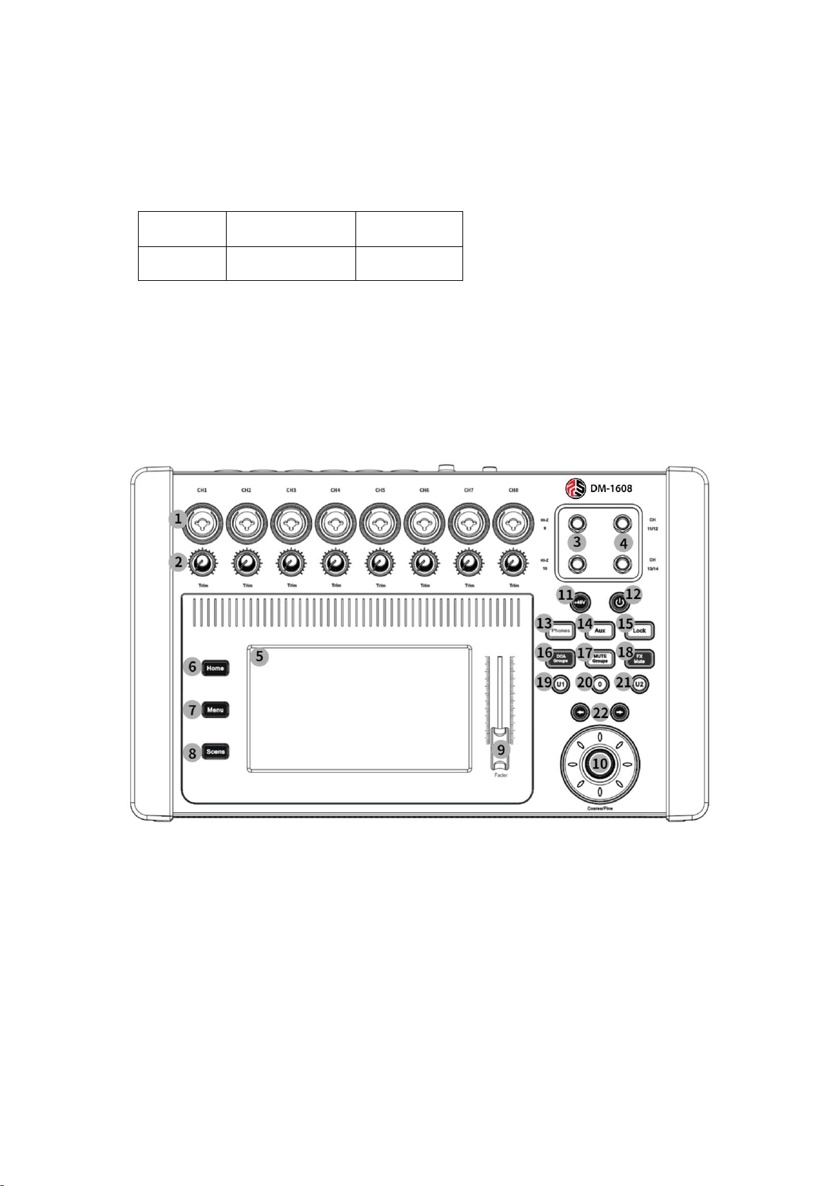
4.1. Front Panel:
① CH1-CH8: Balanced XLR/TRS combination mono input jacks.
② Trim Knob: Before analog-to-digital conversion, channels 1-8 adjust the analog input
signal level.
③ HI-Z 9-10: High-resistance mono channels for instrument inputs.
④ CH11-CH14 : TRS stereo input interface.
⑤ 7" HD LCD touch screen.
⑥ Home Button: Return to the main interface.
⑦ Menu Button: Enter the display control and system setting interface.
⑧ Scene Button: Enter the scene preset interface
⑨ FADER: Volume decay fader
⑩ DATA WHEEL: Change the selected value or position can be fine-tuned parameters and
scroll through the list.
11 +48V Button: Open the phantom power interface and view the status of all channels
with fantasy power on/off
12 Rest screen button.
13 Phones Button: Monitor level volume control.
14 AUX Button: Navigate to the AUX overview interface.
15 Lock Button: Operating system interface lock to prevent misuse (default
password:123456)
16 DCA Groups Button: Navigation to the interface where DCA groups can be controlled and
edited.
17 Mute Groups Button: Navigate to the interface where the mute groupings can be
controlled and edited.
18 FX Mute Button: Mute or unmute all effect channels.
19 U1 Button: User-defined button.
20 O Button: Resets the current output channel gain value to the default value (0dB).
21 U2 Button: User-defined button.
22 Key: Navigate left or right.
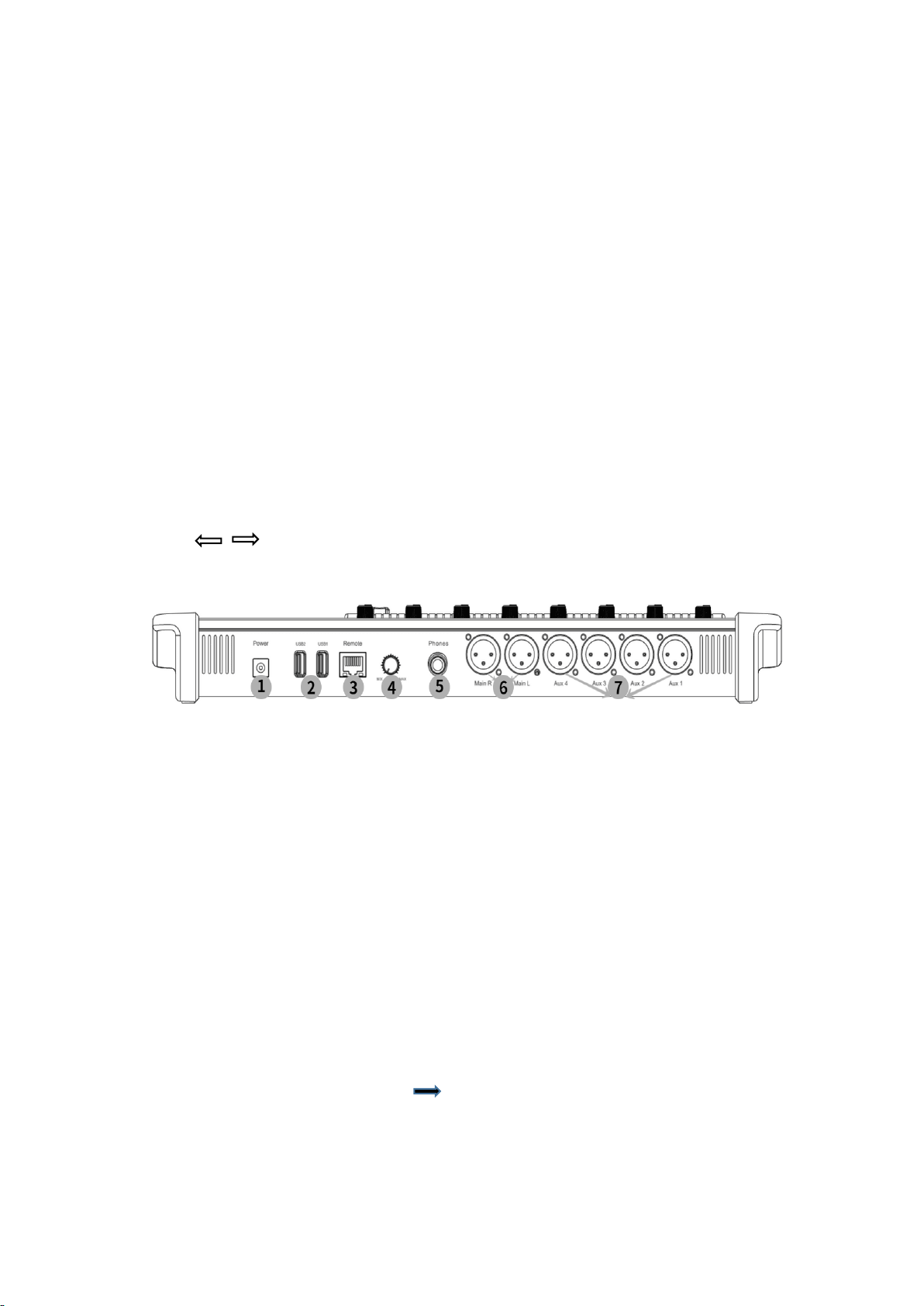
4.2. Back Panel:
①Power Supply: Please use the power supply included with the mixer, please do not use
other power supplies instead.
②USB 2.0 (Class A): For connecting USB storage devices and WIFI adapters.
③Remote: Ethernet interface for connecting to PC-based interactive software.
④Trim knob: Used to adjust the signal level of the monitor interface.
⑤Monitor: Stereo TRS interface when the monitor channel is activated line or headphone
output is diverted to this output channel.
⑥Main R/L: Balanced XLR male interface.
⑦AUX:Auxiliary output 1 to 4 channels, balanced XLR male connector.
5. Instructions for Use
5.1. Software and Documentation Download
① View Device IP Address: Enter [Menu] [Network] to view the device IP address
information, the default is automatically assigned by DHCP, you can choose to set the IP address
manually.
② Download: Open the browser, enter the IP address of the device, click "Enter" to navigate to
将

the download interface, providing three download options: audio files, operating instructions /
user manuals, interactive software download (support systems Windows, Android, Mac, IOS,
linux).
③ Default Password: (LOCK, scene reset password) 123456.
5.2. PC Software Login
① Maunal IP: Input IP address to search for devices manually for connection.
② Scan: Search for devices, and all devices in the same network segment can be found.
③ Device List: Display the name and IP address of online devices.
④ Connect: Select the listed devices, click "Connect" to connect and jump to the main
interface automatically.
5.3. Main Interface
①Navigation Bar: Displaying the type of channel and the channel range.

②Function Overview: Display the current channel has been opened (GEQ, COMP, Gate) function.
③Channel Name: Display the channel name (customizable name), touch to navigate to the
channel configuration interface.
④Sound and Image Slider: Adjust the distribution image of the sound source in space, touch to
slide or use the data wheel to adjust.
⑤Solo: Routing the signal of this channel to the listening interface.
⑥48: Show that the channel has phantom power turned on.
⑦Ø:Shows that the channel has changed the input signal polarity.
⑧ D: Shows that the current channel has been programmed into DCA grouping.
⑨ M: Shows that the current channel has been programmed into the Mute group.
⑩ Level Meter: Display the current channel real-time signal level.
⑪ Channel Fader: Touch the fader to adjust the current channel gain.
⑫ LINK: Link the channel with the adjacent channel, and all the channel settings will be copied to
the adjacent channel.
⑬ Mute: Channel mute (red display), orange display means the channel is muted by mute group
or DCA group mute.
5.4. Input Channel
5.4.1. Overview
①Overview: Displays the channel control enabled for the current channel.
②Reset: Restores All parameter configurations in this interface to their default state.
③Polarity Reverse: Change the polarity of the current input signal.
④Delay: Displays the delay configuration and delay information.
⑤Digital Gain: Control the channel digital gain (+/-15dB) by slider.
⑥DCA Groups: Shows that the channel has been assigned to a DCA group.
⑦Mute Groups: Shows that the channel has been assigned to a mute group.
⑧EQ(ON/OFF): Turns on/off the equalizer and displays the EQ zone graph.
⑨Comp (ON/OFF): Turns on/off the compressor and displays the graph.
⑩Gate (ON/OFF): Turns the noise gate on/off and displays the graph.
11 AUX Sends: Sends the current channel signal to the AUX auxiliary output channel.
12 FX Sends: Sends the current pass signal to the FX effects channel.
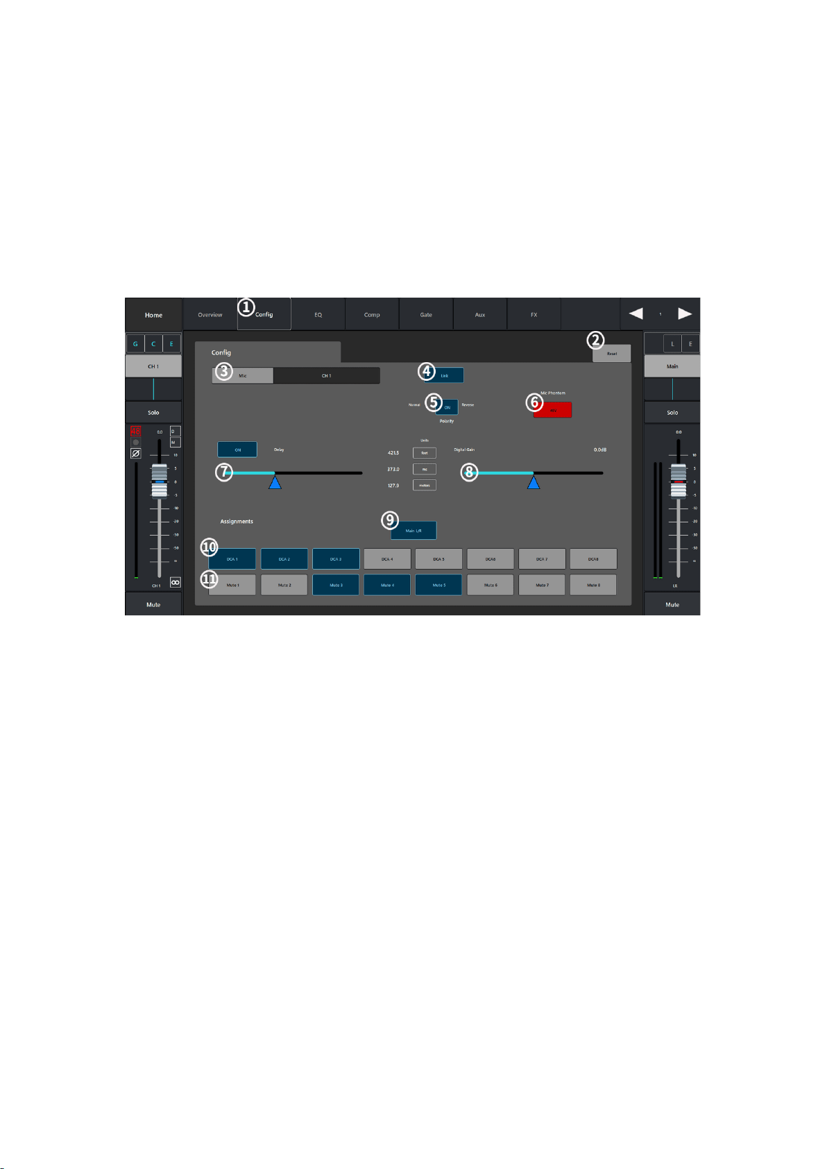
5.4.2. Config
①Config: Parameter configuration interface.
②Reset: Restore the current interface parameter configuration to the default value.
③MIC: Display the channel name, touch the keyboard to display the custom name of the
channel.
④Link: Link the channel with the adjacent channel, and all the channel settings will be copied
to the adjacent channel.
⑤Polarity: Change the polarity of the current channel input signal.
⑥Mic Phantom: Turn on or off the phantom power of the channel
⑦Delay: Turn on or off the current channel delay timer (delay range: 0-1000ms).
⑧Digital Gain: Control the channel digital gain (+/-15dB) through the slider.
⑨Main L/R: Route the channel signal to the Main channel output.
⑩DCA Groups: Shows that the channel has been assigned to a DCA grouping.
11 Mute Groups: Shows that the channel has been assigned to a mute group.;

5.4.3. EQ
① EQ :Equalizer configuration interface.
② Reset:Restore the current interface parameter configuration to default values.
③ RTA On: Turn on/off the real-time analyzer.
④ ON Button: Turn on or off the equalizer.
⑤ RTA Display: Display the channel signal amplitude and peak value.
⑥ Parametric Equalizer Graph: Graphical representation of the equalizer curve according to the
parameter configuration.
⑦ Low-Cut Filter/High-Cut Filter Button: The filter will be set by the frequency controller as the
cut-off frequency, and the frequency higher or lower than the cut-off frequency will be weakened.
⑧ Low-Cut Filter/High-Cut Filter: Change the equalizer band 1 and band 4 from parametric filter
to shelf filter, no bandwidth control is provided when the shelf filter is enabled.
⑨ Band 1-4 Button: Enable/Disable the relevant parametric equalizer band, the band is fully
parameterized, the frequency range is 20Hz-40KHz;
⑩ Freq: Set the cut-off frequency rate of the low-cut/high-cut filter.
⑪ Gain: Adjusts the gain under the frequency setting of the associated EQ band, in the range of
-15dB to +15dB;
⑫ Freq: Set the center frequency of the correlation equalizer band, if the shelf filter is enabled,
the Freq control is used to set the inflection frequency of the shelf filter.
⑬ Q knob: Adjusts the bandwidth of the associated equalizer band, the bandwidth control will
be hidden when the shelf filter is selected.
⑭ The auxiliary slider is applied to fine-tune the parameters.

5.4.4. Comp
① Compressor: Configuration interface.
② Reset: Restore all parameter settings in this interface to their default values.
③ ON: Turn on/off the compressor.
④ IN: Display the input level.
⑤ Compressor Graph: Compressor graph with horizontal scale from 0dB to - 60dB.
⑥ G.R: Display the signal level attenuated by the compressor.
⑦ Out: Display the output level after compressor processing
⑧ Threshold: Set the threshold value for the compressor to start attenuating the signal level,
when the input signal exceeds the threshold value, it will start working.
⑨ Ratio: Set the input/output compression ratio when the input signal exceeds the threshold.
⑩ Gain: Adjust the total output gain to compensate for the loss of signal level after compression.
⑪ Attack: Set the start time of the compressor when the signal exceeds the threshold.
⑫ Release: Set the release time for the compressor to stop compressing when the signal is below
the threshold.
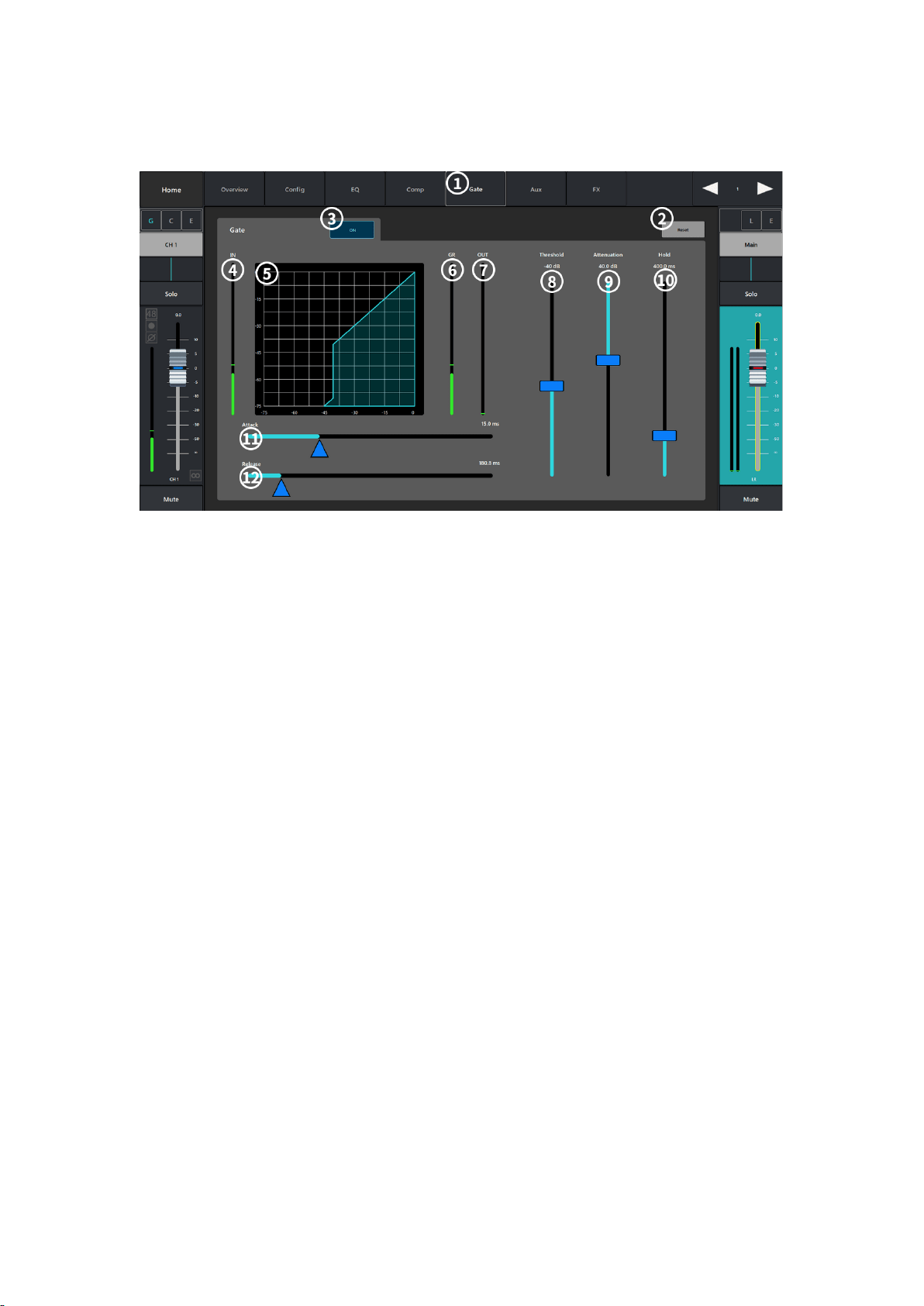
5.4.5. Gate
① Gate: Noise gate configuration interface.
② Reset: Restore all parameter settings in this interface to their default values.
③ ON: Turn on/off the noise gate.
④ IN: Input level.
⑤ Noise Gate Graph: Noise gate graph with horizontal scale from 0dB to - 75dB.
⑥ G.R: Display of the signal level reduced by the noise gate.
(7) Out: Display the output level after the noise gate processing
⑧ Threshold: Set the threshold value through which the audio signal is allowed to pass, when the
signal is below the threshold value it will be attenuated by the noise gate.
⑨ Attenuation: Set the amount of output signal attenuation when the input signal is below the
threshold.
⑩ Hold: Set the time that the noise gate remains open after opening and the length of time that
the noise gate remains open when the input level drops below the threshold.
⑪ Attack: Set the response speed of the noise gate when the signal exceeds the threshold.
⑫ Release: Set the response speed of the noise gate to attenuate the audio signal when the signal
is below the threshold.

5.4.6. AUX Sends
①AUX: Auxiliary transmit configuration interface.
②Reset button: Restores all parameter settings in this interface to their default values.
③Auxiliary output channel name.
④Auxiliaries send slider: Set the audio signal level sent from this channel to the AUX auxiliary
output channel.
⑤Display the gain value of the current send channel.
⑥Mute: mute the auxiliary send channel without affecting any other auxiliary outputs or sends.;
⑦Touch the drop-down box to send Pre_Fdr/Post_Fdr/Pre_Dyn/Per_All signals to the AXU
output channels.
5.4.7. FX Sends

① FX effect sending configuration interface.
② Reset: restore all parameter settings in this interface to their default values.
③ FX effect channel name.
④ Send Slider: Set the audio signal level of the channel to send to the effect mix signal.
⑤ Display the gain value of the current send channel.
⑥ Touch the drop-down paragraph to select the effect type.
⑦ Touch the drop-down box to select the send Pre_Fdr/Post_Fdr signal to the FX effect mixer
channel.
5.5. Output Channels
5.5.1. Overview
① Overview :Overview screen.
② Reset:Restores all parameter settings in this interface to their default values.
③ Delay: Display the delay configuration and delay information.
⑫ DCA Groups: Display the channel has been assigned to DCA groups.
⑬ Mute Groups: Shows that the channel has been assigned to mute groups.
④ (GEQ) ON: Turn on or off the equalizer.
⑤ (Limiter) ON: Turn on or off the pressure limiter.

5.5.2. config
①Config: Parameter configuration interface.
②Reset: Restore all parameter settings in this interface to their default values.
③Mic: Display the channel name, touch the display keyboard to customize the channel name.
④ON: Turn on or off the delay timer, and display the delay configuration and information.
⑤DCA Groups: Shows that the channel has been assigned to a DCA grouping.
⑥Mute Groups: Shows that the channel has been assigned to a mute group;
5.5.3. PEQ
① PEQ parametric equalizer configuration interface.
② Reset: restore the current interface parameter configuration to default values.
③ RTA On: turn on/off the real-time analyzer.
④ ON: Turn on or off the equalizer.
⑤ RTA Display: Display the channel signal amplitude and peak value.
⑥ Graphical representation of the equalizer curve according to the equalizer parameter
configuration.
⑦ Low-Cut/High-Cut Filter: the filter uses the corresponding frequency controller set frequency
as the cut-off frequency, and will weaken the frequency higher or lower than the cut-off frequency.
⑧ Low-cut Shelf/High-Cut Shelf Filter: Change the equalizer band 1 to channel 6 from the
parametric filter to the shelf filter, which does not provide bandwidth control when the shelf filter
is enabled.
⑨ Enabling or disabling different bands of the parametric equalizer.
⑩ Freq (low-cut/high-cut): set the inflection frequency of the low-cut/high-cut filter.
⑪ Gain: Adjusts and displays the gain at the frequency setting of the relevant EQ band, ranging
from -15db to +15dB;
⑫ Freq:Adjust and display the center frequency of the equalizer, the center frequency range of
all bands is 20Hz to 20KHz, if the shelf filter Freq control is enabled for setting the inflection
frequency of the shelf filter.
⑬ Q: Adjusts the bandwidth of the relevant equalizer band, if the shelf filter is selected, the
bandwidth control will be hidden.
⑭ The auxiliary slider is applied to fine-tune the parameters.
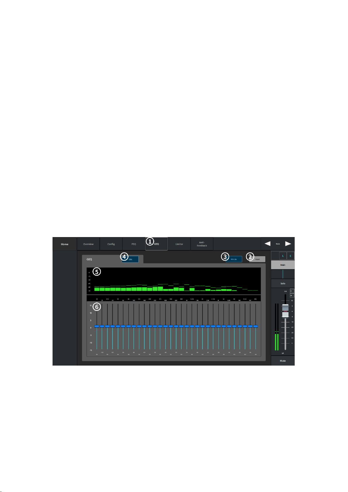
5.5.4. GEQ
① GEQ graphic equalizer configuration interface.
② Reset: Restoring the current interface parameter configuration to default values.
③ RTA On: Turn on/off the real-time analyzer.
④ ON: Turn on or off the equalizer.
⑤ RTA Display: Display the channel signal amplitude and peak value.
⑥ Graphic Equalizer: 31-band graphic equalizer control, select the corresponding frequency band
to push the slider to set parameters.

5.5.5. comp/Limiter
①Comp: Compressor configuration interface.
②Reset: Restore all parameter settings in this interface to their default values.
③ON: Turn on/off the compressor.
④IN: Display the input level.
⑤Compressor Graph: Compressor graph with horizontal scale from 0dB to - 60dB.
⑥G.R: Display the signal level attenuated by the compressor.
⑦Out: Display the output level after compressor processing
⑧Threshold: Set the threshold value for the compressor to start attenuating the signal level,
when the input signal exceeds the threshold value, it will start working.
⑨Ratio: Set the input/output compression ratio when the input signal exceeds the threshold.
⑩Gain: Adjust the total output gain to compensate for the loss of signal level after compression.
11 Attack: Set the response time for the compressor to start working when the signal exceeds
the threshold.
12 Release: Set the response time for the compressor to stop compressing when the signal is
below the threshold.
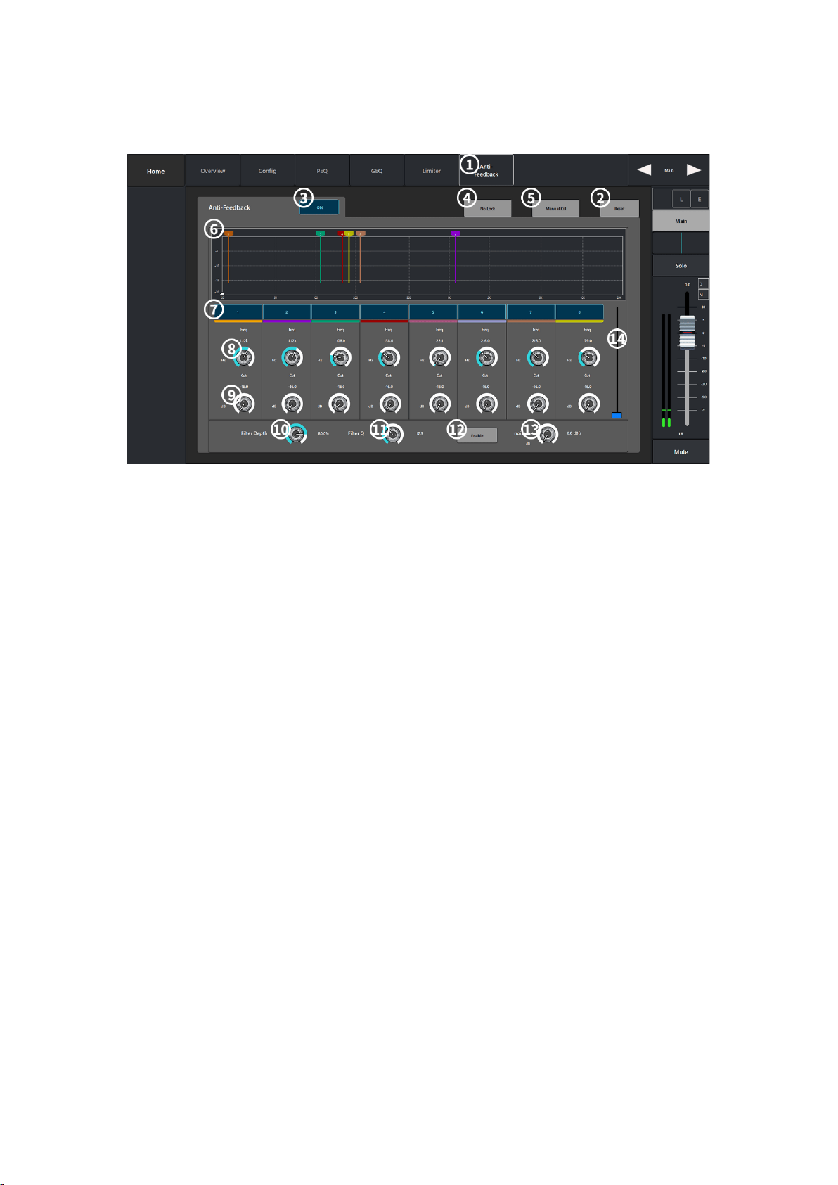
5.5.6. Anti-Feedback
①Anti-Feedback: Parameter configuration interface.
②Reset: Restore all parameter settings in this interface to their default values.
③ON: Enable/disable feedback suppression.
④NO Lock: Display the current identified feedback frequency.
⑤Manual Kill: When a suspicious feedback frequency is identified, touch this button to apply a
filter at that frequency.
⑥Display: Display the whistle point of different frequencies captured by the filter and the
amount of attenuation.
⑦Filters: Enable or disable the filters of different frequency bands.
⑧Freq: Set the center frequency of the filter.
⑨Cut: Set the amount of filter attenuation.
⑩Filter Depth%: Increase or decrease the depth of all filters.
11 Filter Q: Set the bandwidth of all filters.
12 Noise:Noise gain setting; ⑫ Noise:noise gain setting
13 Auxiliary slider for parameter fine-tuning.;

5.6. FX Effects Channels
5.6.1. Overview
① Overview :Overview screen.
② Reset: Restore all parameter settings in this interface to their default values.
③ Effect Pick OFF: Select the Pre_Fdr/Post_Fdr signal.
④ Delay: Display the delay configuration and delay information.
⑤ DCA Groups: Shows that the channel has been assigned to a DCA group.
⑥ Mute Groups: Shows that the channel has been assigned to a mute group.
(vii) ON: turns on the EQ curve overview graph.
⑧ AUX Sends: Sends the current effect signal to the auxiliary output channel.
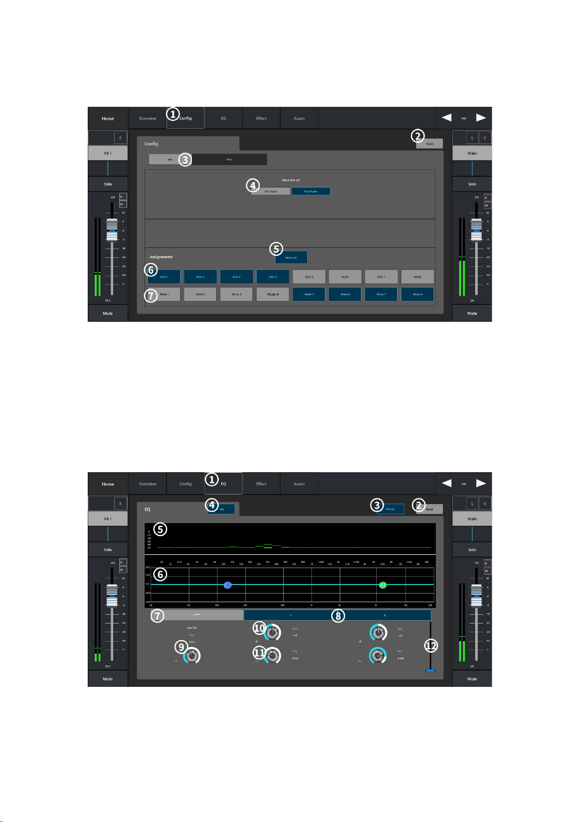
5.6.2. config
①Config: Parameter configuration interface.
②Reset: Restore all parameter settings in this interface to their default values.
③Mic: Display the channel name, touch the display keyboard to customize the channel name.
④Effect Pick OFF: Select Pre_Fdr/Post_Fdr signal.
⑤Main L/R: Send the current channel signal to the main output channel.
⑥DCA Groups: Show that the channel has been assigned to a DCA grouping.
⑦Mute Groups: Shows that the channel has been assigned to a mute group.
5.6.3. EQ
①EQ: Parameter configuration interface.
②Reset: Restore the current interface parameter configuration to the default value.
Table of contents


