Barrus SHIRE 14 70 WB User manual
SHIRE WORK BOAT MANUAL
SHIRE 14 70 WB
SHIRE 14 85 WB
SHIRE 14 130 WB
Please read in conjunction with either
Yanmar or John Deere Operational Manual
&
PRM Gearbox Manual
optional:
VDO Travel Power Manual
Note there may be several optional extras, or alternative components, that might be
fitted to an engine that are not shown in this book.
Enter your engine identification details in the spaces provided above.
E. P. BARRUS LIMITED, Launton Road, Bicester, Oxfordshire. OX26 4UR
Tel: 01869-363636 Fax: 01869-363610 www.barrus.co.uk
RDG603A11 - Issue 8 - Shire 14 70, 85 & 130 WB Owners Manual Page 2 of 50
Declaration of Conformity for Recreational Craft Propulsion
Engine with the requirements of Directive 94/25/EC as amended
by 2003/44/EC.
Name of Engine Manufacturer: Yanmar Co Ltd.
Address: Yanmar Europe B.V, Brugplein 11, 1332 BS Almere-de Vaart, Netherlands.
Name of Authorised Representative: E.P.Barrus Ltd
Address: E.P.Barrus Ltd, Launton Road, Bicester, Oxon, OX26 4UR, England
Engine type approved according to: Stage II of Directive 97/68/EC, 88/77/EC
Description of Engine(s) and Essential Requirements
Engine Type: Inboard Engine Fuel Type: Diesel
Combustion Cycle: 4 Stroke
Identification of Engine(s) covered by this Declaration of Conformity
Engine Model
Engine Type
Engine Family code
Type Approval Certificate Number
Shire 70 WB
4 TNV 98 NSA
YD3300DNMGEC
e13*97/68GA*2001/63*0545*11
Essential Requirements
Standards
Other normative
document/method.
Technical
file
Specify in more detail
*= Mandatory standard.
Annex 1.B- Exhaust Emissions
B.1 Engine Identification
B.2 Exhaust emission
requirements
*
* EN ISO 8178- 1:1996
B.3 Durability
B.4 Owners Manual
Annex 1. C- Noise Emissions
See Declaration of Conformity of the craft in which the engine(s) has(have) been installed
This declaration of conformity is issued under the sole responsibility of the manufacturer. I declare on
behalf of the engine manufacturer that the engine(s) [is (are) in conformity with the type(s) for which
above mentioned EC type-examination or type approval certificate(s) has (have) been issued and]1will
meet the exhaust emission requirements of Directive 94/25/EC as amended by Directive 2003/44/EC
when installed in a recreational craft, in accordance with the engine manufacturer’s supplied instructions
and that this (these) engine(s) must not be put into service until the recreational craft which it is (they are)
to be installed has been declared in conformity with the relevant provisions of the above mentioned
Directives.
Tim Hart
Sales Director
Signed: Bicester, UK

RDG603A11 - Issue 8 - Shire 14 70, 85 & 130 WB Owners Manual Page 3 of 50
Declaration of Conformity for Recreational Craft Propulsion
Engine with the requirements of Directive 94/25/EC as amended
by 2003/44/EC.
Name of Engine Manufacturer: John Deere Power Systems
Address: Usine de Saran, B.P. 11013, 45401 Fleury-les-Aubrais Cedex, France
Name of Authorised Representative: E.P.Barrus Ltd
Address: E.P.Barrus Ltd, Launton Road, Bicester, Oxon, OX26 4UR, England
Engine type approved according to: Stage II of Directive 97/68/EC, 88/77/EC
Description of Engine(s) and Essential Requirements
Engine Type: Inboard Engine Fuel Type: Diesel
Combustion Cycle: 4 Stroke
Identification of Engine(s) covered by this Declaration of Conformity
Engine Model
Engine Type
Engine Family code
Type Approval Certificate Number
Shire 85 WB
4045DF270BME
5JDXL04.5076
e11*97/68GA*2002/88*0219*00
Essential Requirements
Standards
Other normative
document/method.
Technical
file
Specify in more detail
*= Mandatory standard.
Annex 1.B- Exhaust Emissions
B.1 Engine Identification
B.2 Exhaust emission
requirements
*
* EN ISO 8178- 1:1996
B.3 Durability
B.4 Owners Manual
Annex 1. C- Noise Emissions
See Declaration of Conformity of the craft in which the engine(s) has(have) been installed
This declaration of conformity is issued under the sole responsibility of the manufacturer. I declare on
behalf of the engine manufacturer that the engine(s) [is (are) in conformity with the type(s) for which
above mentioned EC type-examination or type approval certificate(s) has (have) been issued and]1will
meet the exhaust emission requirements of Directive 94/25/EC as amended by Directive 2003/44/EC
when installed in a recreational craft, in accordance with the engine manufacturer’s supplied instructions
and that this (these) engine(s) must not be put into service until the recreational craft which it is (they are)
to be installed has been declared in conformity with the relevant provisions of the above mentioned
Directives.
Tim Hart
Sales Director
Signed: Bicester, UK

RDG603A11 - Issue 8 - Shire 14 70, 85 & 130 WB Owners Manual Page 4 of 50
PLEASE NOTE:
This manual has been compiled to help you to operate your engine and its associated
parts with safety and pleasure. Please read it carefully and familiarise yourself with the
engine and its parts before operation.
E.P.Barrus reserve the right to change the specification of its products and manuals
without prior notice.
Depending upon the equipment specification of the engine and accessories fitted, there
may be discrepancies with the information presented in this handbook. No claims may
be pursued in this respect.
WARNING:
THIS MANUAL FORMS AN INTEGRAL PART OF THE ENGINE IT ACCOMPANIES, IF
A TRANSFER OF TITLE OCCURS, IT MUST ALWAYS BE HANDED OVER TO THE
NEW OWNER.
WARRANTY
This Limited Warranty provides coverage for three (3) years (or 2000 hours which ever
occurs first) for commercial users from the date of warranty registration. The repair or
replacement of parts, or the performance of service under this warranty, does not
extend the life of this warranty beyond its original expiry date.
PRM gearboxes are covered by a two (2) year warranty.
To ensure that you have been registered for your warranty, please ask your Boat-
Builder or Engine supplier to provide your portion of the registration form.
The Warranty will only apply if the following have been carried out:
1/ The Installation Check List in the Installation Section has been fully completed.
2/ The boat builder or engine installer has completed the Boat Builder Section on the
Service Record Card (located at the back of this manual) regarding hand over and
commissioning of boat.
.
3/ The registration form has been completed and returned to E.P Barrus.
Engine alternator, starter motor and electrical components are only covered by a one
(1) year warranty.

RDG603A11 - Issue 8 - Shire 14 70, 85 & 130 WB Owners Manual Page 5 of 50
CONDITIONS THAT MUST BE MET IN ORDER TO OBTAIN WARRANTY
COVERAGE
Warranty coverage is only available from an authorised dealer in the country in which
the sale occurred. Routine maintenance outlined in the Owners Manual must be
performed using genuine parts in order to maintain warranty coverage. If the customer
performs maintenance, Barrus reserves the right to make future warranty coverage
possible only with proof of proper maintenance.
WARRANTY CLAIMS
Warranty claims shall be made by an authorised dealer or boat builder.
The dealer or boat builder will then arrange for the inspection and any necessary
repairs. If the repairs carried out are not covered by the warranty, purchaser shall pay
for all related labour and material, and any other expenses associated with that service.
WHAT IS NOT COVERED
This limited warranty does not cover routine maintenance items, adjustments, normal
wear and tear, damage caused by abnormal use, operation of the product in a manner
inconsistent with the recommended operation/duty cycle section of the Owners Manual,
accident, submersion, improper installation (proper installation specification and
techniques are set forth in the Operations and First time running sections in this
manual), use of an accessory or part not manufactured or sold by us, or alteration or
removal of parts. Expenses related to crane-out, launch, towing, storage, telephone,
rental, inconvenience, slip fees, insurance coverage, loan payments, loss of time, loss
of income, or any other types of accidental or consequential damages are not covered
by this warranty.
Failure to use John Deere approved oils and coolants will invalidate any warranty (Shire
90).
Engine electrical systems fitted with alternator boost charge systems or any other
electrical management systems other than those approved by Barrus are not covered
by warranty.
Engine and fuel equipment is not covered by warranty if bio-diesel is used in the fuel
system. Also if no type of water trap is incorporated into fuel system.
Damage due to rust or corrosion, submersion, or unreasonable exposure to the
environment, such as exposure to high humidity, rain fall, or seawater, or conditions
resulting in the freezing of cooling water are also not covered.

RDG603A11 - Issue 8 - Shire 14 70, 85 & 130 WB Owners Manual Page 6 of 50
Contents
SECTION 1 - SAFETY PRECAUTIONS...................................................................................................... 8
1. General....................................................................................................................................... 8
2. Lifting.......................................................................................................................................... 8
3. Rotating Shafts and Belts........................................................................................................... 8
4. Exhaust System.......................................................................................................................... 8
5. Launching and Lifting Boats....................................................................................................... 8
6. Batteries ..................................................................................................................................... 8
SECTION 2 - ENGINE IDENTIFICATION.................................................................................................. 10
SECTION 3 - INSTALLATION................................................................................................................... 11
1. Ventilation................................................................................................................................. 11
2. Engine Beds............................................................................................................................. 11
3. Pressurised Water Header Tank.............................................................................................. 11
4. Shaft Connection and Propeller selection................................................................................ 13
5. Engine Anti-Vibration Mounts................................................................................................... 13
6. Engine Mount Installation......................................................................................................... 14
7. Engine Alignment ..................................................................................................................... 16
8. Electrics.................................................................................................................................... 17
9. Electrical Options...................................................................................................................... 18
10. Engine Oil................................................................................................................................. 19
11. Fuel........................................................................................................................................... 19
12. Coolant..................................................................................................................................... 20
13. Calorifier (optional)................................................................................................................... 20
14. Control Cables.......................................................................................................................... 21
15. Domestic Battery Bank (with optional Twin Alternator Engines).............................................. 21
16. Control Panel............................................................................................................................ 22
17. Seawater Strainer..................................................................................................................... 23
16. Exhaust System........................................................................................................................ 23
17. Hydraulic Drive Transmissions................................................................................................. 24
18. Hydraulic Pump Drive (Shire 70).............................................................................................. 24
19. Installation Check list................................................................................................................ 25
SECTION 4 - OPERATION........................................................................................................................ 26
1. Starting The Engine For The First Time................................................................................... 26
2. Starting Procedure ................................................................................................................... 26
3. Stopping Procedure.................................................................................................................. 26
4. Refuelling.................................................................................................................................. 26
5. Diesel Fuel Additive.................................................................................................................. 27
6. Exhaust Back Pressure............................................................................................................ 27
SECTION 5 - SERVICE PROCEDURE ..................................................................................................... 28
1. Engine Oil and Filter Change................................................................................................... 28
2. Air Filter Check & Change........................................................................................................ 29
3. Gearbox Oil Change................................................................................................................. 29
4. Disposal of Oil and Related Items............................................................................................ 30
5. Primary Fuel Filter Water Drain................................................................................................ 30
6. Primary Fuel Filter Change ...................................................................................................... 31
7. Secondary Fuel Filter Change.................................................................................................. 31
8. Fuel System Bleeding .............................................................................................................. 32
9. Cooling System ........................................................................................................................ 32
10. Belt Adjustment ........................................................................................................................ 32
11. Belt Maintenance...................................................................................................................... 33
12. Belt Replacement..................................................................................................................... 33
13. Deluxe Panel Maintenance ...................................................................................................... 34
14. Sacrificial Anode Change......................................................................................................... 35
15. Raw Water Pump Impeller Change.......................................................................................... 35
16. Engine Heat Exchanger Tube Stack Flushing. ........................................................................ 35

RDG603A11 - Issue 8 - Shire 14 70, 85 & 130 WB Owners Manual Page 7 of 50
17. Winterization of Seawater Cooling System.............................................................................. 36
SECTION 6 - SERVICE PARTS ................................................................................................................ 37
SECTION 7 - SERVICE SCHEDULE......................................................................................................... 39
SECTION 8 - WIRING DIAGRAMS ........................................................................................................... 41
1. Engine Wiring Diagram Shire 70 WB....................................................................................... 41
2. Engine Wiring Diagram, Shire 85/130 WB............................................................................... 42
3. Deluxe Control Panel Wiring Diagram...................................................................................... 43
4. RDG20710111 - Deluxe Control Panel.................................................................................... 44
5. VDO 8kW Wiring diagram and overall dimensions .................................................................. 45
6. 5kW VDO Travel Power System.............................................................................................. 46
SECTION 9 –AFTERLIFE RECYCLING .................................................................................................. 47
SECTION 10 - DEALER LIST.................................................................................................................... 48
SERVICE RECORD CARD........................................................................................................................ 50

RDG603A11 - Issue 8 - Shire 14 70, 85 & 130 WB Owners Manual Page 8 of 50
SECTION 1 - Safety Precautions
1. General
It is the responsibility of the installer/operator to ensure that the finished installation
complies with the relevant health & safety requirements and the recreational craft
directive before commissioning.
Ensure that the engine battery isolator switch is in the off position and the key removed
from the control panel before carrying out any maintenance or repairs.
2. Lifting
The lifting points supplied with the engine are for lifting the engine/gearbox only. A
suitable spreader bar must be employed to prevent over-stressing either bracket during
any lift.
3. Rotating Shafts and Belts
The engine and its accessories are not intended to be put into operation until it is
integrated into the boat as a whole. No person should be in the engine compartment
whilst the engine is running.
4. Exhaust System
Exhaust gases may have temperatures as high as 650oc and contain elements which
are harmful if ingested. It is therefore essential that exhaust systems are gas tight and
lagged to prevent accidental burning.
5. Launching and Lifting Boats
Care must be taken when launching or craning new boats into or out of the waterway,
so that water does not enter the engine via the exhaust system or air vents. It is
recommended that these are blocked temporarily whilst undertaking this procedure.
6. Batteries
WARNING:
EXPLOSIVE GASES / SULPHURIC ACID
•Batteries can produce explosive gases, keep sparks and flames away from the
battery. NO SMOKING.
•Batteries contain sulphuric acid; if splashed on skin or eyes, flush well with water
and seek medical advice.
•Keep the battery tops and battery compartment ventilated at all times.

RDG603A11 - Issue 8 - Shire 14 70, 85 & 130 WB Owners Manual Page 9 of 50
•If disconnecting the battery; remove the earth lead FIRST; and re-connect it last.
•If charging the battery; ensure that the charger is switched off before connecting and
disconnecting.
•Do not tip the battery on its side.
•Please see label on battery or manufacturer’s instructions for specific information.

RDG603A11 - Issue 8 - Shire 14 70, 85 & 130 WB Owners Manual Page 10 of 50
SECTION 2 - Engine Identification
Please quote the engine identification number during any enquiry or when ordering
spare parts.
This is found engraved into the brass plate, on top of the engine rocker cover and
stamped to the crankcase above the starter motor.
An example of the engine identification plate is as follows:
Figure 2-1: Engine Identification Badge
Note: There are a number of optional extras that may be fitted to an engine for particular
customer’s engine that are not listed here.
A list of common item service part numbers can be found in Shire service parts, in
Section 6.
RDG603A11 - Issue 8 - Shire 14 70, 85 & 130 WB Owners Manual Page 11 of 50
SECTION 3 - Installation
1. Ventilation
•All internal combustion engines radiate heat and require cool, clean air for complete
combustion purposes.
•Please ensure that adequate engine room ventilation is provided, by fitting at least
two vents of an aperture of not less than 15,000 mm2each (24 in2).
An allowance must be made for any grills or louvres placed in the airflows and
generally, an increase of 25% in area is sufficient to overcome any restriction
problems.
2. Engine Beds
•These should be a minimum of 10mm thick and extended rearward and be welded
to the hull and forward to the bulkhead. There must be webs or gussets welded in
place to prevent flexing. They may be steel or stainless steel glassed into a GRP
hull.
3. Pressurised Water Header Tank
•The pressurised header tank should be mounted higher than the level of the engine
and no more than 1 metre from the engine, to prevent cooling system air locks.
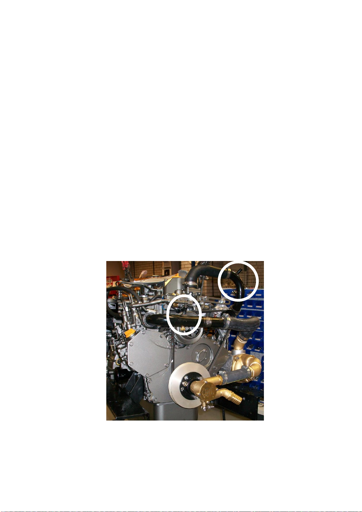
Figure 3-1: Shire 70 WB Header Tank Connections

RDG603A11 - Issue 8 - Shire 14 70, 85 & 130 WB Owners Manual Page 12 of 50
•Shire 70/85 WB - The smaller internal diameter hose tail (left side of tank) should be
connected to the top of the engine. This is the air-bleed. The larger internal diameter
hose-tail (right side of tank) should be connected to the lower pipe on the engine
(circled left). This is the water-fill.
Figure 3-2: Shire 85 WB Header Tank Connections (Crank mounted pump)
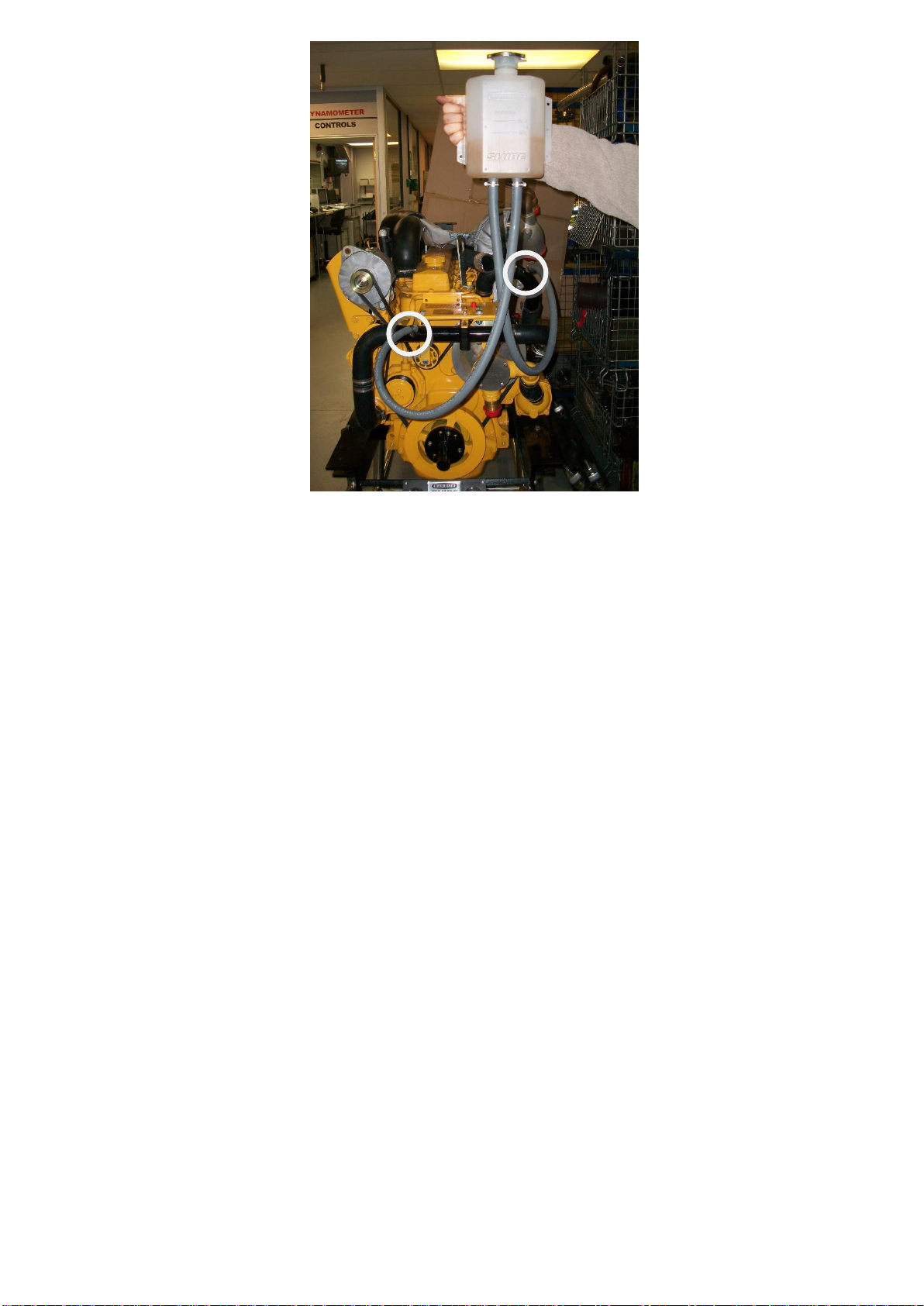
RDG603A11 - Issue 8 - Shire 14 70, 85 & 130 WB Owners Manual Page 13 of 50
Figure 3-3: Shire 85/130 WB Header Tank Connections (Belt Driven Pump)
4. Shaft Connection and Propeller selection
•Some type of flexible coupling must be used to connect the gearbox output flange to
the propeller shaft flange. Various coupling flanges are widely available to assist with
this.
•Please note, underperforming engines will not be covered under warranty if the
cause of the poor performance is found to be the use of an inappropriate propeller.
5. Engine Anti-Vibration Mounts
•Ensure that the engine feet do not end up at the top of the thread on the engine
mounts, this puts undue pressure on them and can result in excessive engine
movement and premature mount failure. Mount the engine using the steel packing
plates supplied under the engine mounts RDG3906, see general arrangement
drawings.
•Ensure that the engine has been installed for at least 24 hours before shaft
alignment is checked, this allows the mounts time to settle under the engine weight.
•Ensure that the anti-vibration mount centre screw is sufficiently raised so as not to
touch the engine bed. If this occurs excessive engine vibration will be experienced
through the hull.
RDG603A11 - Issue 8 - Shire 14 70, 85 & 130 WB Owners Manual Page 14 of 50
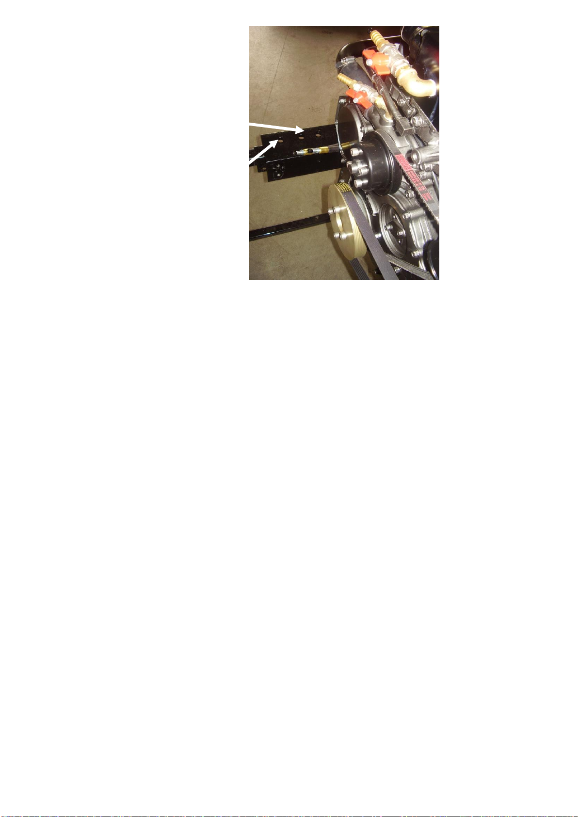
•For best results, fit the front anti vibration mounts into the front holes in the engine
rails. If engine room space is a problem the mounts can be fitted slightly further back
in alternative holes, and the front of the rail cut off –leaving 50mm of material to
retain strength (measuring from the centre of the mount hole to the front end of the
rail). Note: this procedure is only possible on non VDO travel power engines, and
may result in a very slight increase in vibration.
•The anti vibration mounts have a small number stamped in to them, a Shire 70 WB
has “45”and Shire 85/130 WB has “55”.
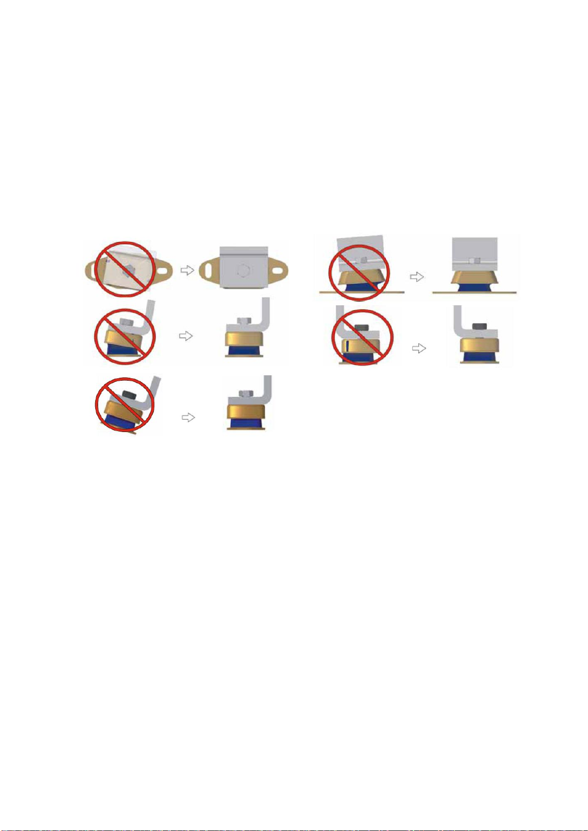
6. Engine Mount Installation
Figure 3-4: Correct Anti-Vibration Mount Installation
•Care should taken to install mounts parallel to the engine rails with the washer and
locknut firmly tightened on the cover of the mount. The maximum distance from the
top of the locknut to the base of the adjusting nut must not exceed 5mm; any greater
adjustment should be made using shims.

RDG603A11 - Issue 8 - Shire 14 70, 85 & 130 WB Owners Manual Page 15 of 50
Figure 3-5: Correct Anti-Vibration Mount Installation
RDG603A11 - Issue 8 - Shire 14 70, 85 & 130 WB Owners Manual Page 16 of 50
Figure 3-6: Anti-Vibration Mount Installation Points
7. Engine Alignment
•The gearbox output shaft flange and propeller shaft input flange must be almost
perfectly aligned. A maximum of 0.05mm (0.002") misalignment in any plane is
acceptable. Ensure alignment is rechecked after the first 4 hours of running, at the
end of the first month and annually thereafter.
•If the engine is out of alignment it will result in excessive vibration and possible
damage to the stern tube and propeller shaft.
•Boats that are fitted with fully flexible drive couplings should still have the engine and
shaft alignment as close as possible. A dummy shaft may be required for this
purpose.
(Note: some types of flexible shaft couplings require the input and output to be
misaligned, check with the coupling manufacturer’s installation instructions).
Normal mounting position.
Alternative mounting position if
engine compartment space is
restricted.

RDG603A11 - Issue 8 - Shire 14 70, 85 & 130 WB Owners Manual Page 17 of 50
8. Electrics
WARNING:
The blue link wire must be removed when the domestic battery positive terminal lead has
been connected to the terminal post.
Do not run the engine without this wire in place or without the domestic battery positive lead
connected otherwise alternator damage will occur.
If the engine is going to run for more than 1 hour with the blue link wire in place, remove
domestic alternator drive belt to prevent alternator damage.
Single Alternators
•On engines fitted with single alternators, connect the main positive battery cable to
the starter motor solenoid terminal.
•Do not attach any part, hose or cable to the engine wiring harness. There is a
warning label attached to the harness to remind you of this.
•Connect the wiring extension harness multi plug to the panel plug, and the other end
to the engine.
•Connect the start battery positive cable to the engine starter motor solenoid terminal.
•Starter motor battery cable size to be a minimum of 50mm2.
Twin Alternators
•Shire 70 WB - Connect the domestic battery positive cable to the 240A alternator
“Pos out” terminal (see wiring diagram). This ensures that the 50A alternator
charges the start battery and the 240A alternator charges the domestic battery. Twin
alternators remove the requirement for a split charging system or relay.
•Shire 85/130WB - Connect the domestic battery positive cable to the 120A alternator
B+ terminal (see wiring diagram). This ensures that the 140A charges the start
battery.
•Use 50mm2cable for 240A alternator and 40mm2cable for 140A
•Both negative battery terminals can be connected to a common earth point.

RDG603A11 - Issue 8 - Shire 14 70, 85 & 130 WB Owners Manual Page 18 of 50
Belt Replacement
•Ensure that you have the correct new belt prior to starting this procedure. Loosen
the top adjuster bolts, and the lower mounting pivot nut and bolt.
•Push the alternator towards the engine to loosen the belt.
•Remove the seawater pump (may not be required, depending on seawater pump
option fitted).
•Remove the belt.
•Hold the belt in position over the top alternator pulley; rotate the engine, if
required, by hand, to guide the new belt into the pulley “V”s check it is correctly
seated in the pulley.
•Replace seawater pump (if required).
•Re-tension the belt as above.
Note: Some engines maybe fitted with a side mounted belt driven seawater pump.
Similar belt tightening procedure will apply for this.
9. Electrical Options
•If the engine is fitted with the optional VDO travel power system, refer to the manual
supplied with it for correct wiring, control box installation and operation.
•The Shire range can be supplied with other optional additional 12v or 24v
alternators. A 24 V Alternator will be supplied fitted but not wired. It is the
responsibility of the boat builder to ensure that this is correctly wired to the boats
electrical system.
CAUTION:
REMOVE THE IGNITION KEY BEFORE WORKING IN ENGINE COMPARTMENT.

RDG603A11 - Issue 8 - Shire 14 70, 85 & 130 WB Owners Manual Page 19 of 50
10. Engine Oil
•All Shire engines are supplied fully run in.
•Check oil levels in engine and gearbox before starting. (The gearbox uses the same
grade of oil as the engine).
•Shire 70 WB -- use Shire engine oil SAE 15w / 40 API class CD.
•Shire 85/130 WB -- use John Deere engine oil, part number VC83070-020.
WARNING:
ENGINE OIL WITH A HIGHER API CLASS THAN SPECIFIED IS UNSUITABLE FOR
CANAL BOAT ENGINE OPERATION AND WILL CAUSE ENGINE DAMAGE IF USED.
11. Fuel
•Ensure the main fuel tank is clear of dirt & water.
•A separate water trap must be fitted to all engine installations. (The engine is
supplied with a small water trap as standard).
•Connect fuel feed and return hoses from engine to main fuel tank via supply and
return lines. Ensure that they are connected the correct way around.
•Shire 70 WB –connect the inlet to the electric fuel pump inlet hose.
•Shire 85/130 WB –connect to the inlet to the primary fuel filter inlet hose.
•The fuel supply and return hoses are fitted with 10mm (3/8”) hose tails.
•The engine hoses should have sufficient slack to absorb engine movement without
placing strain on the hoses, and be securely clipped to prevent accidental damage
and chafing.
•Initially fill the fuel system loosening the bleed bolt on the top of the primary fuel
filter/water trap. For Shire 70 WB, turn on the ignition to operate the electric fuel
pump. For Shire 85/130 WB, pump the primer on the primary filter. Close when fuel
begins to flow clearly (no bubbles). It is rarely necessary to bleed the injection pump
or injectors upon installation as the engine will already have fuel in it from the engine
run-in and test procedure.

RDG603A11 - Issue 8 - Shire 14 70, 85 & 130 WB Owners Manual Page 20 of 50
12. Coolant
•Yanmar (Shire 70 WB) recommend a prepared coolant mix of 50% clean tap water
and 50% antifreeze, John Deere (Shire 85 WB) recommend that Coolguard be used,
part number EPH76215-020.
•To fill the cooling system for the first time, add coolant to the engine through the
white plastic expansion bottle.
•Open the calorifier taps (where fitted) to fill the calorifier system and displace air.
•After running the engine for the first time, monitor the water level frequently as
trapped air bubbles may be expelled. Top up the system as necessary. Fill the skin
tank via the inlet hose connection or filler plug if fitted.
13. Calorifier (optional)
•The temperature of coolant flowing to the calorifier from the engine can be between
85°C-90°C. A blender valve must be incorporated in the calorifier/hot water system
outlet to lower the hot water temperature for domestic use.
Figure 3-7: Shire 70 WB Calorifier Connections
Calorifier
outlet
Calorifier
inlet
This manual suits for next models
2
Table of contents
Other Barrus Boat manuals


