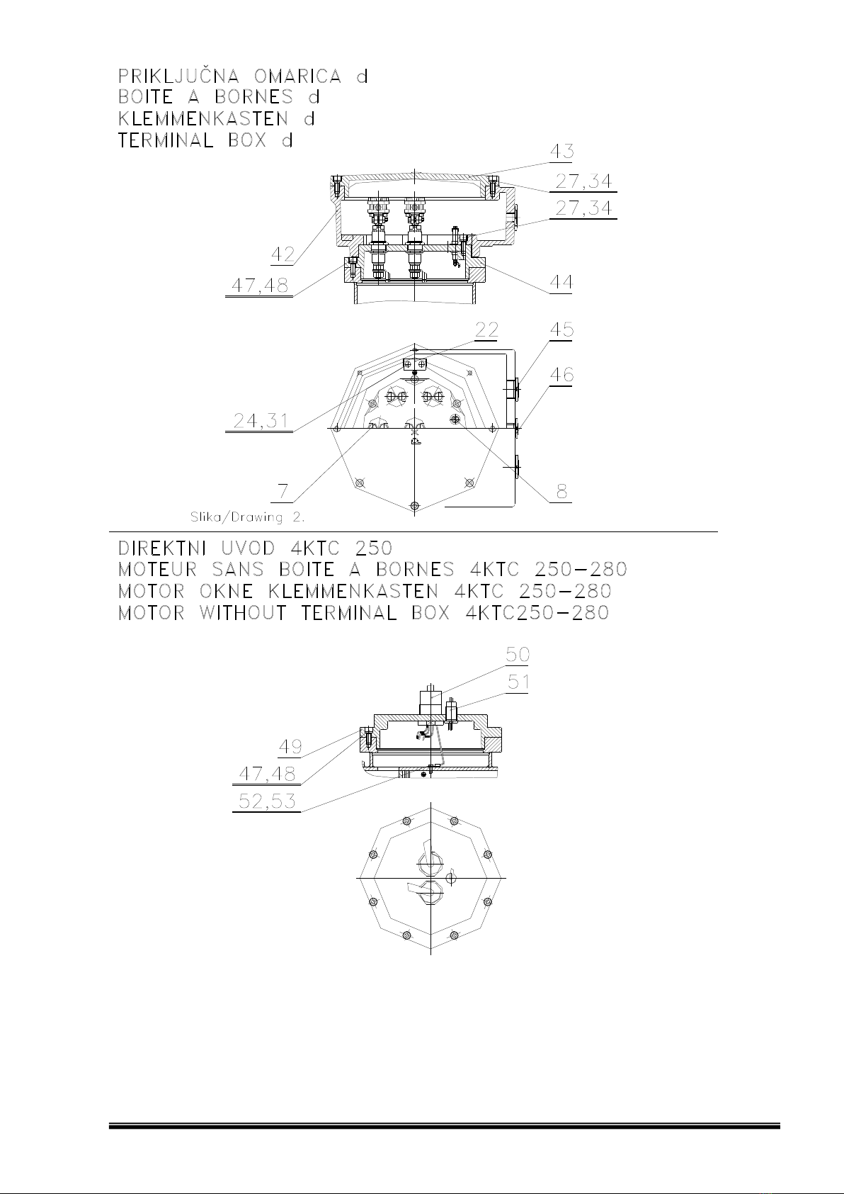
Bartec Varnost 4KTC 250 User manual

1
ELEKTROMOTORJI V
PROTIEKSPLOZIJSKI ZAŠČITI
SQUIRREL-CAGE MOTORS
DRUCKFESTGEKAPSELTE
MOTOREN
II 2G Ex db IIC T* Gb / II 2G Ex db e IIC T* Gb
II 2G Ex db IIB T* Gb / II 2G Ex db e IIB T* Gb
4KTC 250 - 315

2
3
-
4
SPARE PARTS (DRAWING)
ERSATZTEILE (BILD)
REZERVNI DELI (RISBA)
5
-
1
1
PARTS LIST
ERSATZTEILLISTE
SEZNAM REZERVNIOH DELOV
12
-
1
6
INSTALLATION GUIDELINES FOR SQUIRREL
-
AGE MOTORS
17
-
2
1
AUFSTELLUNGSRI HTLINIEN FÜR DRU KFESTGEKAP
SELTE MOTOREN
22
-
2
5
NAVOD
ILA ZA MONTAŽO IN PRIKLJUČITEV
2
6
LIFTING POINTS FOR MOTOR LIFT
HEBEVORRI HTUNG FÜR DEN TRANSPORT
DVIŽNA MESTA ZA PRESTAVLJANJE
2
6
ONNE TION DIAGRAMM
ANS HLUSS S HALTBILD
VEZNI NAČRT
27
-
3
1
ERTIFI ATE OF ONFORMITY
BVS 15 ATEX E 075 X
KONFORMITÄTSBES HEINIGUNG BVS 15 ATEX E 075 X
ERTIFIKAT O SKLADNOSTI BVS 15 ATEX E 075 X
3
2
-
3
5
ERTIFI ATE OF ONFORMITY
IEXEx BVS 1
5
.0
066
1X
KONFORMITÄTSBES HEINIGUNG BVS BVS 15.0066X
ERTIFIKAT O SKLADNOSTI BVS BVS 15.0066X
3
6
E DE LARATION OF ONFORMITY
EG KONFORMITÄTSERKLÄRUNG
IZJAVA O SKLADNOSTI E
3
7
-
3
8
RE Y LING
39
-
40
RE Y LING
41
-
4
2
RE IKLAŽA

3

4

POS. Nr.
ODE ARTI LE
DENOMINATION
QUANTITE
ITEM No.
PART No.
DENOMINATION
QUANTITY
POS. Nr.
ARTIKEL Nr.
BEZEI HNUNG
ANZAHL
POZI IJA
RAZPOZ
NAVNA
ŠT.
IME
KOLIČINA
5
1.
SHAFT ROTOR UNIT
1
LAÜFER
ROTOR
4KT 250
4KT 280
4KT 315
261807 M2 *
261809 M4 *
261812 M6 *
M8 *
262438 S2 *
262440 S4 *
262443 S6 *
262443 S8 *
262446 M2 *
262449 M4 *
262452 M6 *
262455 M8 *
263191 S2 *
263193 S4 *
262443 S6 *
262443 S8 *
263197 MA-2
*
293108 MB-2
*
263201 MB-4
*
263202 MA-4
*
M6 *
M8 *
L2 *
L4 *
263206 L6 *
L8 *
2.
END SHILD BS
1
LAGERS HILD BS
STATORJEV ŠČIT BS
4KT 250
4KT 280
4KT 315
261843 *
262487 *
263230 *
3.
END SHILD AS
1
LAGERS HILD AS
STATORJEV ŠČIT AS
4KT 250
4KT 280
4KT 315
261846 *
262491 *
263233 *
4. FLANGE STAN AR 1
FLANSCH GENORMT
PRIROBNICA
4KT 250
4KT 280
4KT 315
261851 * *
263239 *

POS. Nr.
ODE ARTI LE
DENOMINATION
QUANTITE
ITEM No.
PART No.
DENOMINATION
QUANTITY
POS. Nr.
ARTIKEL Nr.
BEZEI HNUNG
ANZAHL
POZI IJA
RAZPOZ
NAVNA
ŠT.
IME
KOLIČINA
6
5.
TERMINAL BOX 4KT 250
-
315 Exe
1
KLEMMENKASTEN 4KT 250
-
315 Exe
PRIKLJUČNA OMARI A 4KT 250
-
315 Exe
263274 *
6.
OVER 4KT 250
-
315 Exe
1
KLEMMENKASTENDE KEL 4KT 250
-
315 Ex
e
POKROV PRIKLJUČNE OMARI E 4KT 250
-
315 Exe
263011 *
7.
TERMINAL STUD
3(6)
LEITUNGSDUR HFUHRUNGEN
PREVODNIK
010915 K 12/750 *
008417 K 12/1100 *
8.
TERMINAL STUD
P
T
LEITUNGSDUR HFUHRUNGEN
P
T
PREVODNIK
P
T
269327 K 6/750 2
004798 M38x1,5 -6x 1
004795 M24x1,5 -4x 1
9.
INNER BEARING OVER
2
LAGERDE KEL INNEN
VMESNIK
4KTC 250 4KTC 280 4KTC 315
261817 *
262458 *
263213 *
10. FAN 2-poles 1
LUFTER –2polig
VENTILATOR 2-polni
4KTC 250 4KTC 280 4KTC 315
261667 *
262264 *
262976 *
11. FAN 4,6,8-poles 1
LUFTER 4,6,8polig
VENTILATOR 4,6,8-polni
4KTC 250 4KTC 280 4KTC 315
*
262265 *
262979 *

POS. Nr.
ODE ARTI LE
DENOMINATION
QUANTITE
ITEM No.
PART No.
DENOMINATION
QUANTITY
POS. Nr.
ARTIKEL Nr.
BEZEI HNUNG
ANZAHL
POZI IJA
RAZPOZ
NAVNA
ŠT.
IME
KOLIČINA
7
12. FAN COVER 1
LUFTERHAUBE
VENTILATORSKI ŠČIT
4KTC 250 4KTC 280 4KTC 315
261650 *
262265 *
262961 *
13. FAN COVER WITH RAIN CUP IMV1/IMV5 1
LUFTERHAUBE MIT REGENSCHUTZ ACH IMV1/IMV5
VENTILATORSKI ŠČIT IMV1/IMV5
4KTC 250 4KTC 280 4KTC 315
261659 *
262255 *
262965 *
14. BEARING BS 2
LAGER BS
LEŽAJ BS
4KTC 250 4KTC 280 4KTC 315
268764 63142ZC3 1
268765 63162ZC3 1
268767 63172ZC3 1
15. BEARING AS 2
LAGER AS
LEŽAJ AS
4KTC 250 4KTC 280 4KTC 315
268764 63142ZC3 1
268765 63162ZC3 1
268818 NU317C3 1
16. OIL SEAL IN 3760 NBR 2
ICHTRING IN 3760 NBR
OLJNO TESNILO IN 3760 NBR
4KTC 250 4KTC 280 4KTC 315
268837 A13x70x100 1
268836 A13x80x105 1
290977 A13x85x115 1
17. SEAL FOR TERMINAL BOX Exe 1
KLEMMENKASTEN ICHTUNG Exe
TESNILO
268851 *
18.
ABLE GLAND Exe
1(2)
KABELVERS HRAUBUNG Exe
DOVODNI A Exe
122418 M50x1,5 *
243235 M63x1,5 *

POS. Nr.
ODE ARTI LE
DENOMINATION
QUANTITE
ITEM No.
PART No.
DENOMINATION
QUANTITY
POS. Nr.
ARTIKEL Nr.
BEZEI HNUNG
ANZAHL
POZI IJA
RAZPOZ
NAVNA
ŠT.
IME
KOLIČINA
8
19.
ABLE GLAND Exe
P
T
1
KABELVERS HRAUBUNG Exe
P
T
U
VODNI A Exe
P
T
122394 M20x1,5 *
EXTERNAL CIRCLIP IN 471
SPRENGRING IN 471
VSKOČNIK IN 471
20. 4KTC 250 4KTC 280 4KTC 315
268966 68 1
268968 78 1
268970 80 1
21. 4KTC 250 4KTC 280 4KTC 315
268967 70 2
268970 80 2
268971 85 2
22. EARTH PLATE 1
ER UNGSPLATTE
OZEMLJILNA PLOŠČICA
4KTC 250-280 4KTC 315
261670 *
262980 *
23. LACH WASHER 1
SICHERUNGSSHEIBE
PRITR ILNA PLOŠČICA
262981 *
HEXAGON BOLTS
SECHSKANTSCHRAUBEN
VIJAK S ŠESTROBO GLAVO
24. 271819 M8x25 2
25. 271753 M8x25 2
HEXAGO SOCKET HEA BOL
INNERSECHKANTSCHRAUBEN
VIJAK S ŠESTROBO LUKNJO
26. 271763 M12x20
3
27. 271831 M10x25
16
28. 4KTC 250 - 280 4KTC 315
271845 M12x30
16 24
29. 4KTC 250 4KTC 280 4KTC 315
271851 M12x60
8
271851 M12x70
8 12

POS. Nr.
ODE ARTI LE
DENOMINATION
QUANTITE
ITEM No.
PART No.
DENOMINATION
QUANTITY
POS. Nr.
ARTIKEL Nr.
BEZEI HNUNG
ANZAHL
POZI IJA
RAZPOZ
NAVNA
ŠT.
IME
KOLIČINA
9
30. 4KTC 250 4KTC 280 4KTC 315
271851 M12x65
8
271853 M12x70
8 8
SPRING VASHER
GLATTET FE ERING
VZMETNA PO LOŽKA
31. 271723 8 2
32. 271723 8 2
33. 271712 12 3
34. 271699 10 12
35. 4KTC 250-280 4KTC 315
271712 12 16 24
36. 4KTC 250-280 4KTC 315
271712 12 8 12
37. 271712 12 8
KEY 1
PASSFE ER
MOZNIK
38. 4KTC 250 4KTC 280 4KTC 315
272035 A18x11x130
272035 A18x11x130- 2p
272036 A20x12x130- 4,6,8p
272035 A18x11x130- 2p
271630 A22x14x160- 4,6,8p
39. 4KTC 250 4KTC 280 4KTC 315
272050 B20x12x20
B20x12x30
271660 B22x14x28
40. BEARING COVER AS 1
LAGER ECKEL AS
LEŽAJNI ŠČIT AS
4KTC 250 4KTC 280 4KTC 315
261824 *
262465 *
263217 *
41. BEARING COVER BS 1
LAGER ECKEL BS
LEŽAJNI ŠČIT BS
4KTC 250 4KTC 280 4KTC 315
261823 *
262464 *
263217 *

POS. Nr.
ODE ARTI LE
DENOMINATION
QUANTITE
ITEM No.
PART No.
DENOMINATION
QUANTITY
POS. Nr.
ARTIKEL Nr.
BEZEI HNUNG
ANZAHL
POZI IJA
RAZPOZ
NAVNA
ŠT.
IME
KOLIČINA
10
42.
TERMINAL BOX 4KT 250
-
315 Exd
1
KLEM
MENKASTEN 4KT 250
-
315 Exd
PRIKLJUČNA OMARI A 4KT 250
-
315 Exd
263318 *
43.
OVER FOR TERMINAL BOX 4KT 250
-
315 Exd
1
KLEMMENKASTENDE KEL 4KT 250
-
315 Exd
POKROV PRIKLJUČNE OMARI E 4KT 250
-
315 Exd
263316 *
44.
TERMINAL PLATE
1
ANS HUSS
PLATTE
VMESNA PLOŠČA
45.
PLUG Exd
2
VERS HLUSSSTOPFEN Exd
SLEPI ČEP Exd
273968 *
46.
PLUG Exd
P
T
1
VERS HLUSSSTOPFEN Exd
P
T
SLEPI ČEP Exd
P
T
273970 *
HEXAGO SOCKET HEA BOL
INNERSECHKANTSCHRAUBEN
VIJAK S ŠESTROBO LUKNJO
47. 271831 M10x25
6
48. SPRING VASHER
FE ERRING
VZMETNA PO LOŽKA
271699 10 6
49.
TERMINAL PLATE DRAW OUT ABLE 4KT 250
1
DE KEL FÜR KABEL AUSFÜHRUNG 4KT 250
VMESNA PLOŠČA DIREKTNI UVOD 4KT 250
*
50.
DIRE T ABLE ENTRIE
1
KABELAUSGANG
DIREKTNI VHOD
M48x1.5 *
51.
DIRE T
ABLE
P
T
1
PT KABELAUSGANG
DIREKTNI VHOD
P
T
M24x1.5 *

POS. Nr.
ODE ARTI LE
DENOMINATION
QUANTITE
ITEM No.
PART No.
DENOMINATION
QUANTITY
POS. Nr.
ARTIKEL Nr.
BEZEI HNUNG
ANZAHL
POZI IJA
RAZPOZ
NAVNA
ŠT.
IME
KOLIČINA
11
52. SLOTE HEA BOL AN SCREW 1
SCHLITZSCHRAUBEN
VALJNI VIJAK
273784 M8x10 *
53. SPRING VASHER 1
FE ERRING
VZMETNA PO LOŽKA
271723 8 *
Pri naročilu nadomestnega dela, prosimo
navedite:
Pozicija, tip motorja, serijska številka.
PRIMER:
When ordering spare parts, please state:
Item No., motor type, serial No.
EXAMPLE:
Bei Ersatzteil Bestellung sind folgende
Angaben erforderlich:
Ersatzteillbezeichnung Typ, Motornummer
Serial Nr.
BEISPIEL:
ATTENTION: THE SPARE PARTS WRITTEN IN BOLD LETTERS ARE SUBJE T TO DIMENSIONAL
A URA Y INSPE TION (SEE EN 60079-0, EN 60079-1).
A HTUNG: DIE MASSE DER FETT GEDRU KT GEKENNZEI HNETTEN ERSATZTEILE MÜSSEN
BESONDEREN GENAUIGKEITSKONTROLLEN UNTERZOGEN WERDEN (SIEHE EN
60079-0, EN 60079-1).
OPOMBA: SESTAVNI DELI, NAPISANI Z POUDARJENIMI ČRKAMI SO POSEBEJ KONTROLIRANI
(GLEJ EN 60079-0, EN 60079-1).
1.261809 Rotor
4KTC 250 M4
000000
1.261809 Rotor
4KTC 250 M4
000000
1.261809 Rotor
4KTC 250 M4
000000

INSTALLATIONGUIDELINES
FOR 4KTC SQUIRREL- CAGE MOTORS
12
These instructions for the installation and maintenance do not contain all particulars which might arise during
the installation and application of the cage motor. We therefore insist on its being mounted and maintained
by qualified persons (IEC 364).
1. TRANSPORT AND STORAGE
THE MOTORS ARE TO BE STORE IN A CLOSE AN RY AREA. Should they be stored outdoors, it is
important to protect them against bad weather conditions. uring transport make sure that the usual
precautions for this kind of material are respected. 4KTC motors are to be handled with lifting-claw.
2. EXPLOSION PROTE TION ODES
Possible markings
II 2G Ex db IIC T* Gb
II 2G Ex db IIB T* Gb
or
II 2G Ex db e IIC T* Gb
II 2G Ex db e IIB T* Gb
: Ex marking
II: evice group II; equipment can be used in potentially explosive areas except for
mining
2: Category; for use in Zone 1 or Zone 2
G: equipment for use in explosive atmosphere, caused by flamable gas
db: explosion protection type - flameproof enclosure
e: explosion protection type – increased safety
IIC: gas group IIC
IIB : gas group IB
T*: temperature class
2.1 ERTIFI ATE NUMBER
BVS 15 ATEX E 075 X
X – stands for nonconformity of flameproof gaps and joints according to tabels 1 and 2 of EN 60079-1:2014.
3. APPLI ATION AND EXPLOSION PROTE TION
The explosion-proof asynchronous three-phase squirrel-cage motors of the type 4KTC are designed for their
application in industrial buildings with highly explosive atmospheres caused by flammable gases, steam, or
liquids.
Explosion-proof motor versions are:
”Explosion-proof enclosure” for the motor housing and ”Increased safety” for the terminal box according to
EN 60079-0: 2012, EN 60079-1: 2014 and 60079-7: 2007. The cover of the terminal box carries the Ex
imprint.
”Explosion-proof enclosure” for the motor housing and the terminal box according EN 60079-0: 2012 and EN
60079-1: 2014. The cover of the terminal box carries Ex imprint.
The standard electric motor is suitable for the T4 temperature class.
The exact indication of the explosion protection can be found on nameplate of the motor.

INSTALLATIONGUIDELINES
FOR 4KTC SQUIRREL- CAGE MOTORS
13
4. INSTALLATION (MOUNTING) OF THE ELE TRI MOTOR
THE ELECTRIC MOTOR MUST BE MOUNTE BY QUALIFIE PERSONS IN OR ER TO AVOI
POSSIBLE AMAGES URING OPERATION CAUSE BY AN INCORRECT INSTALLATION.
The following rules must be observed during installation:
- strictly adhere to the installation instructions,
- check whether the explosion protection corresponds to the environment or not
(sector, gas group , temperature group),
- check the effects of the environment on the operation of the electric motor (aggressive environment,
temperature, dust ...),
- consider particulars and requirements of room/plant,
- make sure that the correct tools and devices are used,
- observe the motor safety instructions,
- make sure that the means for personal safety are used.
The electric motors are manufactured in such a way as to function in a mildly humid and dusty atmosphere
under temperatures between -50C to 60C without requiring additional protection. If ambient temperature is
below -20
0
C then motors can be equipped with space heaters ( Ex d motors only).
If mounted (installed) outdoors, the motors must be protected from direct sunlight. If the motor is mounted
and operated in vertical position, the fan openings must be protected against the ingress of water or any
other forein objects by fixing the cover above them.
Insulation of the electric motors consists of water-resistant materials and high-quality coating. If stored
correctly, it is therefore not necessary to carry out special tests before connecting the motor to the power
supply.
When mounting the elements (such as clutch, pulley) on to the motor shaft, please pay particular attention to
the bearings. The axial forces caused by possible impacts during installation must not have any effect on the
bearings.
5. ONNE TION TO THE POWER SUPPLY
IMPORTANT!
THE EXPLOSION-PROOF VERSIONS MAY BE MOUNTED AND ONNE TED TO THE POWER
SUPPLY BY QUALIFIED PERSONS ONLY; THE INSTALLER MUST HAVE ADDITIONAL KNOWLEDGE
ABOUT EXPLOSION PROTE TION.
The following items must be checked before the electric motor can be connected to the mains power supply:
- that the data on the label correspond to voltage and frequency of the power supply,
- that the explosion protection indicated corresponds to the environment the electric motor will be operated in
(gas group, temperature class),
- that the installation (pipes or cables) is carried out correctly.
The electric motors rotate clockwise when the phase conductors L1, L2 and L3 are connected to the
terminals U,V,W (1U,1V,1W or U1,V1,W1). Rotation may be changed by switching the terminals on two
phases of conductors.
The following elements are connected to the terminals:
10 – 11 PTC 145°C built in
14 – 15 Thermostats NC (normally closed contact)
16 – 17 Thermostats NO (normally open contact)
The motors are equipped with 3 temperature detectors (PTC thermistor IN 44081 - ….). These temperature
detectors are to be connected to a tripping unit with one of Ex Notified Bodies mark of conformity. The
tripping unit is not protected against explosions and must therefore be installed outside of the hazardous
area. The mark of conformity serves merely to confirm the adherence to the electrical data at the interface
between the temperature detector circuit and the tripping device and to allow the application of both the
tripping device with mark of conformity and the PTC contacts according to IN 44081 for the thermal control
of explosion-proof electric machines.

INSTALLATIONGUIDELINES
FOR 4KTC SQUIRREL- CAGE MOTORS
14
The space heaters are mounted to the terminals 30 – 31 (230V) or 32-33 (110V). Motors with space
heaters are marked with an additional label indicating the nominal data of the heating system.
The electric control unit must make sure that the nominal motor voltage and the heater voltage are not
present simultaneously.
Take particular care over the connection of the cable cores to the terminal board. The insulation of the cable
cores should be close to the terminal, all wires of the flexible cores must be clamped to the terminal.
The tightening torque of the connections on the terminal board must not exceed 7,5 Nm.
Pay close attention to the installation instructions when carrying out the explosion protection of the Ex d
terminal box (»explosion-proof enclosure«) and check for the correct explosion protection cable entry (Ex d
entry).
Prior to the mains connection, check the terminal box for the following items:
- there must not be any dust, pieces of wire or other foreign matters inside of the terminal box,
- the electrical connections must be carried out by qualified persons and the screws must be tightened
correspondingly,
- that the mutual air distance is at least 10 mm for voltages of 400 V or 630 V
- that the unused wires are separated and fixed accordingly,
- all joint areas are formly greased with grease type FOR P -2 (Setral MI P LL/2A) ali Renolit RHF-1 Fuchs
- that the cable is sealed correctly at the cable entry.
- the unused openings must be sealed so as to guarantee that the flame-proof properties are maintained.
The means foreseen to achieve this goal must be such so as to ensure that the sealing-plug can only be
removed with the help of a special tool (according to EN 60079-0: 2012, point, 16.4).
6. PROTE TION OF THE ELE TRI MOTORS AND OPERATION
Succeeding the installation of the electric motors, all rotating parts must be safely protected against contacts.
Only qualified personnel may handle the machines!
In the S1-mode of operation, the motor circuit-breaker is a sufficient device for the maintenance of the
temperature class. To do so, it must be regulated to the rated current of the three-phase cage motor.
In both the S2- and S3- modes of operation and the converter operation, the three-phase cage motors must
be equipped with 3 PTCs in each winding ( IN 44080, IN 44081, IN 44082). The nominal shutdown
temperature of these PTCs are 145
o
C. A corresponding shutdown device with the PTB mark of conformity
(Lab. 3.43) completes the protective system for the maintenance of the temperature class.
Electric motors with two velocities (two separate windings or one winding in ahlander coupling) must have
a separate protection for each speed.
The housing of the electric motor must be connected to the protective conductor, and earthed. The terminal
box contains the screw for the connection of the conductor, the earthing screw sits on the stator housing.
If the electric motor is supplied via the frequency converter, please make sure that the settings on the
converter correspond to the data indicated on the supplementary label. The electric motor must be double-
protected, i.e. with the motor circuit-breaker and the temperature protection. The shutdown device connected
to the temperature protection must be in the range of 2k<Ro<4k with Ro representing the shutdown
resistance. The shutdown device must be certified.
7. MAINTENAN E
Electric motors have a robust structure and need no particular maintenance.
The motor must be cleaned in regular intervals (depending on the environment), especially the entry
openings on the fan as to guarantee a sufficient air flow for the cooling system.
Electric motors feature closed and prelubricated bearings. The life span of the bearings is 20000 service
hours for 2 pol electric motors (ns=3000 min
-1
) under normal operating conditions or 40000 service hours for
4,6,8 and multiple-pol motors.

INSTALLATIONGUIDELINES
FOR 4KTC SQUIRREL- CAGE MOTORS
15
Regular inspections and control measurements carried out by qualified personel are preffered to reduce
possible damages and standstills.
Each deviation from the nominal values (such as higher load current, increased temperatures, vibrations,
unusual noise or smell, reactions of protective devices) is to be understood as signal of possible damage! To
prevent consequential damages on machines or people, please inform the person responsible immediately
on the appearance of such deviations.
8. REPAIRS
ELECTRIC MOTORS FOR EXPLOSIVE AREAS MAY BE REPAIRE EXCLUSIVELY BY THE
MANUFACTURER OR OUR AUTHORIZE REPRESENTATIVE.
THOSE WHO ISASSEMBLE AN REPAIR THE EX MACHINES MUST BE HIGHLY QUALIFIE AN
ISPOSE OF A ITIONAL KNOWLE GE CONCERNING EXPLOSION PROTECTION.
IMPORTANT:
Repaire according of flameproof gaps and joints according to table 2 of EN 60079-1: 2014 is not
allowed! Please conntact producer!
Special attention should be paid that no damaged has occured during disassembly on flameproof gaps and
joints.
Before assembly of electromotor all flameproof gaps and joints needs to be cleaned and greased with
grease type FOR P -2 (Setral MI P LL/2A) or Renolit RHF-1 Fuchs.
If it becomes clear during repairs that the »explosion-proof enclosure« no longer corresponds to the
requirements on the explosion protection and specified in the certification, all markings for explosion
protection must be removed from this motor.
9. S REW TIGHTENING TORQUE
Table 1: Tightening torque: Ex enclosure. Tightening torques for screws of the strength class 8.8 and A4-70.
Thread Tightening
torque (Nm)
Thread Tightening
torque (Nm)
M4 2.3 M12 66
M5 4.6 M14 105
M6 7.9 M16 160
M8 19 M20 330
M10 38 M24 560
Table 2.: Tightening torque: for electrical connections
Thread Tightening
torque (Nm)
Thread Tightening
torque (Nm)
M4 1.2 M10 10
M5 2 M12 15.5
M6 3 M16 30
M8 6 M20 52
10. RE OMENDED TORQUES FOR BARTE -VARNOST STANDARD Exe ABLE GLANDS (Nm)
Table 3.: Recommended tightening torque and terminal sizes for cable glands WISKA, typ ESKE-.. … …..

INSTALLATIONGUIDELINES
FOR 4KTC SQUIRREL- CAGE MOTORS
16
Cable gland size Connection thread (Nm) Pressing screw (Nm) Terminal size (mm)
ESKE-.12 2,0 2,0 3 - 6
ESKE-.16 1,8 1,3 4 - 9
ESKE-.20 2,3 1,5 6 - 13
ESKE-.25 3,0 2,0 7 – 12 / 10 – 17
ESKE-.32 4,5 3,0 13 – 21
ESKE-.40 11,0 10,0 17 - 28
ESKE-.50 13,0 12,0 23 - 35
ESKE-.63 17,0 16,0 31 - 48

AUFSTELLUNGSRICHTLINIEN FÜR DRUCKFEST
GEKAPSELTE MOTOREN BAUREIHE 4 KTC
17
Die nachfolgenden Richtlinien enthalten die wichtigsten Anleitungen für Montage und Wartung
sowie Installation und Anwendung des Elektromotors nach IE 364.
1. TRANSPORT UND LAGERUNG WICHTIG !
IE MOTOREN SOLLEN IN GESCHLOSSENEN, TROCKENEN RÄUMEN GELAGERT WER EN.
Bei Lagerung im Freien müssen sie gegen alle schädlichen Umwelteinflüsse geschützt werden.
Beim Transport ist darauf zu achten, dass die üblichen Vorsichtsmaßnahmen eingehalten werden.
Es muss sichergestellt sein, dass das Wellenende nicht durch Stöße oder Schläge axial oder radial
beschädigt wird, wodurch auch das Kugellager und der Lagersitz Schaden nehmen können.
Für den Transport sind die Hebekrallen zu benutzen.
2. Ex- KENNZEICHNUNG
Mögliche Kennzeichnungen
II 2G Ex db IIC T* Gb
II 2G Ex db IIB T* Gb
oder
II 2G Ex db e IIC T* Gb
II 2G Ex db e IIB T* Gb
: Ex Symbol
II: Gerätegruppe II. er Motor darf in explosionsgefährdeten Bereichen, außer im
Bergbau, eingesetzt werden
2: Kategorie : Für Einsatz in Zone 1. Sehr sicher in gelegentlicher
Ex-Atmosphäre …
G: Ex-Atmosphäre ….verursacht durch Gas
d: Zündschutzart- ruckfeste Kapselung
e: Zündschutzart- Erhöhte Sicherheit
IIC: Explosionsgruppe IIC
IIB : Explosionsgruppe IIB
T*: Temperatureklasse
2.1 EG Baumusterprüfbescheinigungsnummer
BVS 15 ATEX E 075 X
X- Eine Reparatur an den zünddurchschlagsicheren Spalten darf nur entsprechend konstruktiven Vorgaben
des Herstellers erfolgen. ie Reparatur entsprechend den Werten der Tabelle 1 und 2 der EN 60079-1 ist
nicht zulässig.
3. ANWENDUNG UND EXPLOSIONSS HUTZ
rehstrom-Asynchronmotoren in explosions-geschützter Ausführung 4KTC sind für den Betrieb in
Industriegebäuden bestimmt, wo die Gefahr der Explosion von brennbaren Gasen, ämpfen, oder
entzündbaren Flüssigkeiten.
ie explosionsgeschützte Ausführung der Motoren ist folgende :
- ruckfeste Kapselung für das Gehäuse des Motors und "erhöhte Sicherheit" für den Anschlusskasten nach
EN 60079-0:2012, EN 60079-1:2014 und 60079-7:2007. Auf dem eckel des Anschlußkastens steht die
Bezeichnung Ex.

AUFSTELLUNGSRICHTLINIEN FÜR DRUCKFEST
GEKAPSELTE MOTOREN BAUREIHE 4 KTC
18
- ruckfeste Kapselung für das Gehäuse des Motors und für den Anschlusskasten nach EN 60079-0:2012
und EN 60079-1:2014. Auf dem eckel des Anschlußkastens steht die Bezeichnung Ex.
ie Gehäuse der Elektromotoren sind für die Gasgruppe IIC ausgelegt.
ie Standardausführung der Elektromotoren entspricht der Temperaturklasse T4.
ie genaue Bezeichnung des Explosionsschutzes befindet sich auf dem Typenschild.
4. AUFSTELLUNG (MONTAGE) WICHTIG !
IE MONTAGE ES ELEKTROMOTORS ARF NUR VON QUALIFIZIERTEM PERSONAL AUSGEFÜHRT
WER EN, UM EVENTUELLEN BESCHÄ IGUNGEN WÄHREN ES BETRIEBES WEGEN FALSCHER
MONTAGE VORZUBEUGEN.
Bei der Aufstellung des Elektromotors muß man:
- Forderungen der Installationsvorschriften beachten.
- prüfen, ob der Explosionschutz der Umgebung entspricht (Zone, Gasgruppe, Temperaturklasse).
- prüfen, wie die Umgebung auf den Betrieb des Elektromotors einwirkt (aggressive Umgebung, Temperatur,
Staub, usw…).
- Lokale und Fabrikbesonderheiten und Forderungen berücksichtigen.
- die Verwendung von richtigen Werkzeugen und Vorrichtungen sicherstellen.
- Forderungen für sicheren Betrieb beachten.
- die Verwendung von persönlichen Schutzmitteln gewährleisten.
ie Elektromotoren sind derart gefertigt, daß sie ohne zusätzlichen Schutz in mäßig feuchter und staubiger
Atmosphäre mit der Temperatur von -50°C bis +60°C arbeiten können. Für die Temperaturen unter –
20°C müssen die Motoren im Stillstand mit einer Stillstandheizung ausgestattet sein (nur in Exd Ausführung
möglich). Bei der Montage (Aufstellung) des Elektromotors im Freien wird empfohlen, daß der Motor vor
unmittelbarer Sonneneinstrahlung geschützt wird. Auf dem Elektromotor, der in senkrechter Lage betrieben
wird, muß über den Öffnungen der Lüfterhaube ein Schutzdach angebracht sein, um vor Wassereindringen
zu schützen.
ie Isolation der Elektromotoren ist aus Materialen die keine Feuchtigkeit aufnehmen und sehr gut
impregniert sind. eswegen ist es nicht nötig, neue Motoren vor dem Netzanschluss besonders zu prüfen,
wenn sie vorher richtig transportiert und gelagert wurden.
Bei der Montage von Kupplung, Riemenscheibe und anderen Komponenten auf die Welle des
Elektromotors muß ebenfalls beachtet werden, daß durch Schläge oder Stöße kein Schaden entsteht
bzw. die explosionsgeschützte Ausführung des Motors nicht beeinträchtigt wird.
5. NETZANS HLUß WICHTIG ! ! !
ANLAGEN IN EXPLOSIONSGES HÜTZTER AUSFÜHRUNG DÜRFEN NUR FA HLI H QUALIFIZIERTE
PERSONEN AN DAS NETZ MONTIEREN UND ANS HLIEßEN, DIE ÜBER ENTSPRE HENDE
KENNTNISSE AUF DEM GEBIET DES EXPLOSIONSS HUTZES VERFÜGEN !
Vor dem Anschließen des Elektromotors an das Netz muß noch folgendes geprüft werden :
- ob die Angaben auf dem Schild der Spannung und der Frequenz des Netzes entsprechen.
- ob der Explosionsschutz der Umgebung entspricht, in welcher der Elektromotor in Betrieb genommen wird
(Gasgruppe, Temperaturklasse).
- ob die Installation (Rohre oder Kabel) richtig ausgeführt ist.
ie Elektromotoren drehen haben standardmässig rechtslauf , wenn die Phasenleiter L1, L2 und L3 an die
Anschlüsse U, V, W (1U, 1V 1W bzw U1, V1, W1) angeschlossen werden. ie Veränderung der
rehrichtung erreicht man, wenn man die Anschlußstelle von zwei Zuleitungsphasenleitern wechselt. An die
zusätzlichen Anschlussklemmen werden folgende Elemente angeschlossen:
10-11 Kaltleiter 145°C eingebaut
14-15 Thermofühler NC (Öffner)
16-17 Thermofühler NO (Schliesser)
ie Motoren sind mit 3 Temperaturfühlern (Kaltleiter IN 44081 - …) ausgerüstet. iese sind an ein
Auslösegerät, mit dem Prüfzeichen von einer EG zugelassenen Prüfstelle ausgestellt, anzuschlies-sen. Ist
das Auslösegerät nicht explosionsgeschützt. Muss es außerhalb des explosionsgefährdeten Bereiches

AUFSTELLUNGSRICHTLINIEN FÜR DRUCKFEST
GEKAPSELTE MOTOREN BAUREIHE 4 KTC
19
installieren werden. urch das von einer EG zugelassene Prüfstelle ausgestellte Prüfzeichen wird nur die
Einhaltung der elektrischen aten an der Schnittstelle zwischen Temperaturfühlerkreis und Auslösegerät
bestätigt und die Anwendung des Auslösegerätes mit Prüfzeichen und Kaltleitertemperaturfühler gemäß IN
44081 zur thermischen Überwachung explosionsgeschützter elektrischer Maschinen zugelassen.
Auf die Anschlußstellen 30-31 (230V) oder 32-33 (110V) werden die Stillstandsheizungen einge-baut.
Motoren mit Stillstandsheizung sind durch ein Zusatzschild, aus dem die Nenndaten der Heizung ersichtlich
sind, gekennzeichnet.
urch die elektrische Steuerung ist sicherzustellen, daß die Motornennspannung und Heizspannung nicht
gleichzeitig anliegen können.
er Anschluß der Kabeladern auf die Anschlußplatte soll besonders sorgfältig ausgeführt werden. ie
Isolierung der Kabeladern soll sich nahe der Anschlußstelle befinden, alle rähte der feindrähtigen Adern
müssen an der Anschlußstelle eingespannt werden.
as Anzugsmoment der Anschlüsse auf der Anschlußplatte ist maximal 7,5 Nm.
Bei der Ausführung des Explosionsschutzes des Kastens Exd ("druckfeste Kapselung") sind verbindlich die
Installationsvorschriften zu beachten und der richtige Explosionsschutz an der Kabeleinführung ( Exd
Einführung) muß gesichert werden.
Vor dem Netzanschluß ist im Anschlußkasten folgendes zu kontrollieren :
- daß sich im Inneren des Anschlußkastens kein Staub, Reste der rähte und ähnliches befindet,
- daß die elektrischen Verbindungen ordnungsgemäss ausgeführt sind und daß die Schrauben
entsprechend befestigt sind,
- daß die luftstrecke der Spannung 400V oder bei 630V minimal 10 mm beträgt,
- daß die nicht verwendbaren rähte getrennt und entsprechend befestigt sind,
- Alle Spalte sind gleichmäßig mit Fett Typ für P -2 (Setral MI P LL/2A) oder Renolit RHF-1 Fuchs gefettet
- daß die anliegenden Flächen gereinigt und mit einem säurefreien Fett leicht angeschmiert werden,
- daß das Kabel richtig an der Einführung abgedichtet wird.
- daß die nicht benutzten Öffnungen geschlossen werden, so daß die druckfesten genschaften erhalten
bleiben. ie vorgesehenen Mittel um dieses Ziel zu erreichen müssen gewährleisten, daß man die
Verschlußstopfen nur mit Hilfe eines Werkzeuges entfernen kann.
6. S HUTZ DER ELEKTROMOTOREN
IM BETRIEB WICHTIG !
Nach der Aufstellung des Elektromotors müssen alle rotierenden Teile vor Berührung gesichert werden.
Nur qualifiziertes Personal darf die Maschinen betätigen !
In der S1-Betriebsart reicht der Motorschutzschalter als alleinige Maßnahme zur Einhaltung der
Temperaturklasse aus. azu muß er auf den Bemessungsstrom des rehstrommotors eingestellt werden.
In den S2- bis S3 Betriebsarten und bei Umrichterbetrieb müssen die rehstrommotoren mit je 3 in der
Wicklung untergebrachten PTC's nach IN 44080, IN 44081 bzw. IN 44082 ausgestattet werden. ie
Nennabschalttemperatur dieser PTC's beträgt 145°C. Ein entsprechendes Auslösegerät das ein Prüfzeichen
der PTB (Lab. 3.43) besitzt, vervollständigt die Schutzeinrichtung zur Einhaltung der Temperaturklasse.
Elektromotoren mit mehreren Geschwindigkeiten (zwei getrennte Wicklungen oder eine Wicklung mit
ahlanderschaltung) müssen für jede Geschwindigkeit separat geschützt werden.
as Gehäuse des Elektromotors muß mit dem Schutzleiter verbunden werden und geerdet sein. Im
Anschlußkasten befindet sich die Schraube für den Anschluß des Schutzleiters und auf dem Gehäuse des
Stators ist die Schraube für die Erdung.
Falls der Elektromotor über den Frequenzumformer gespeist wird, muß man prüfen, daß die Einstellung des
Umformers dem deklarierten Bereich auf dem Schild entspricht. er Elektromotor muß doppelt geschützt
sein, das bedeutet, mit dem Motorschutzschalter und mit dem Temperaturschutz. as Auslösegerät, das mit

AUFSTELLUNGSRICHTLINIEN FÜR DRUCKFEST
GEKAPSELTE MOTOREN BAUREIHE 4 KTC
20
dem Temperaturschutz verbunden ist, muß sich im Bereich von 2 k<Ro<4k befinden, wobei Ro den
Ausschaltwiderstand darstellt. as Ausschaltgerät muß das Prüfzeichen tragen.
7. WARTUNG
Elektromotoren haben eine robuste Konstruktion und verlangen keine besondere Wartung.
In regelmäßigen Zeitabschnitten (abhängig von der Umgebung) muß der Motor gereinigt werden,
insbesondere die Eintrittsöffnungen auf der Lüfterhaube, so daß eine ausreichende Luftzufuhr für die
Kühlung gewährleistet wird.
Elektromotoren sind mit geschlossenen dauergeschmierten Lagern versehen. ie Lebensdauer der Lager
beträgt 20000 Betriebsstunden von zweipoligen Elektromotoren (ns=3000 min
-1
) bei normalen
Betriebsbedingungen oder 40000 Betriebsstunden von vier- und Mehrpoligen Motoren.
Regelmäßige Inspektionen und Kontrollmessungen, die vom Personal ausgeführt werden, das für solche
Arbeiten qualifiziert ist, sind Maßnahmen, wodurch mögliche Schäden und Betriebsunterbrechungen
vermindert werden.
Jede Abweichung von den Nennwerten (höherer Betriebsstrom, erhöhte Temperatur, Vibrationen,
ungewöhnlicher Lärm oder Geruch, reagieren
von Schutz-Kontrollanlagen usw.) ist ein Zeichen, daß etwas mit dem Betrieb nicht in Ordnung ist !
Um größere Schäden zu verhindern, die unmittelbar oder mittelbar zu weiterem. Schaden bei Personen
oder Materialgütern führen könnten, ist sofort die verantwortliche Person zu benachrichtigen.
8. REPARATUREN WICHTIG !
ELEKTROMOTOREN IN EXPLOSIONSGE-S HÜTZTER AUSFÜHRUNG DARF NUR DER HERSTELLER
ODER DIE BEVOLL-MÄ HTIGTE WERKSTATT REPARIEREN ! ! ! PERSONEN, DIE EX-APPARATE
AUSEINAN-DERNEHMEN UND REPARIEREN, MÜSSEN FA HLI H QUALIFIZIERT SEIN, ÜBER EINE
ZUSÄTZLI HE KENNTNIS AUF DEM GEBIET DES EXPLOSIONSS HUTZES VERFÜGEN UND DIE
ARBEIT MUSS VON EINEM EX- SA HVERSTÄNDIGEN BEGUTA HTET UND ZERTIFIZIERT WERDEN.
Repaire nach der druckfesten Spalten nach Tabelle 2 der EN 60079-1: 2007 ist nicht zulässig!
Von der Montage des Elektromotors müssen alle druckfesten Spalte und Fugen gereinigt und mit Fett Typ
P -2 (Setral MI P LL/2) order Renolit RHF-1 gefettet werden.
Beim Auseinandernehmen von Elektromotoren muß man darauf achten, daß die Oberflächen nicht
beschädigt werden, welche die Ex Schutzspalte bilden ! Bei der Reparatur des Elektromotors müssen alle
Bestandteile der, seitens PTB bestätigter okumentation entsprechen.
Falls bei der Reparatur festgestellt wird, daß die "druckfeste Kapselung" nicht mehr den Forderungen des
Explosionsschutzes und den Forderungen im Zertifikat entspricht, muß von diesem Motor das Zeichen des
Explosionsschutzes beseitigt werden.
9. S HRAUBENVERBINDUNGEN
Tabelle 1: Anzugsdrehmomente für Schrauben der Festigkeitsklasse 8.8 und A4-70 (A4-80) nur in Bauteilen
mit höherer Festigkeit (z. B. Grauguss, Stahl) verwenden.
Gewinde Anzugsdrehmoment
(Nm)
Gewinde Anzugsdrehmoment
(Nm)
M4 2.3 M12 66
M5 4.6 M14 105
M6 7.9 M16 160
M8 19 M20 330
M10 38 M24 560
Tabelle 2: Schraubenverbindungen für elektrische Anschlüsse
This manual suits for next models
2
Table of contents
Languages:
Other Bartec Varnost Engine manuals