nekos
products have been manufactured in accordance with safety standards and
conforms to the stipulations of current standards in force.
When correctly assembled, installed and used according to the present instructions,
they will not generate any danger for persons, animals or items.
Symbols used in the manual
DANGER
Contents
1. Security rules
................................
2.
Construction and standards
3. Technical data
................................
4. ID plate and marking data
................................
5. Electricity supply
................................
5.1.
Section choice of supply cables
6. Assembly
................................
6.1.
Blind support tube and end cap
6.2. Gear motor
................................
6.3.
6.4.
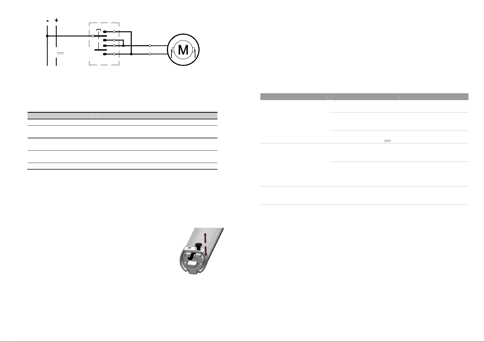
7. Electrical connections
................................
8.
Luminous indications on led
9.
Adjustment of the two stroke
10. Troubleshooting
................................
11.
Indications for correct assembly
12. Environmental protection
................................
13. Warranty
................................
14. Declaration of
incorporation (for a partly completed machine) and EC Declaration of
Conformity
................................
3
INSTRU
products have been manufactured in accordance with safety standards and
conforms to the stipulations of current standards in force.
When correctly assembled, installed and used according to the present instructions,
they will not generate any danger for persons, animals or items.
Symbols used in the manual
This indication draw the attention about potential dangers for
safety and health of peoples and animals.
................................
................................
................................
Construction and standards
................................
................................
................................
................................
................................
................................
................................
................................
................................
................................
................................
Section choice of supply cables
................................
................................
................................
................................
................................
Blind support tube and end cap
................................
................................
................................
................................
................................
................................
................................
................................
................................
................................
................................
................................
Luminous indications on led
................................
................................
Adjustment of the two stroke
-ends ................................
................................
................................
................................
................................
Indications for correct assembly
................................
................................
................................
................................
................................
................................
................................
................................
incorporation (for a partly completed machine) and EC Declaration of
................................
................................
................................
products have been manufactured in accordance with safety standards and
When correctly assembled, installed and used according to the present instructions,
This indication draw the attention about potential dangers for
safety and health of peoples and animals.
................................
....................... 4
................................
................................. 5
................................
...................... 5
................................
.... 6
................................
.................. 6
................................
.................. 6
................................
.............................. 7
................................
.................. 7
................................
................. 7
................................
........................... 8
................................
............................ 8
................................
.......... 8
................................
................................. 9
................................
....................... 9
................................
..................10
................................
..........................10
................................
....10
................................
.............................11
incorporation (for a partly completed machine) and EC Declaration of
................................
...........................12
1. Security rules
I
The Nekos electrical actuators comply with the Machinery Directive (2006/42/EC), Standard
IEC 60335-2-
103 (Particular requirements for drives for gates, doors and windows) and
other directives and regulations indicated in the attached Declarations of Incor
CE Conformity (at the end of the manual). According to the Machinery Directive, actuators
are “partly completed machinery” intended for incorporation into doors and windows. The
manufacturer/supplier of the window is required, with exclusive r
compliance of the entire system with the applicable standards and to issue CE certification.
We strongly discourage any use of the actuators other than that specified and therefore, in
any case, the supplier of the complete sys
For systems installed at a height of less than 2.5 m above floor level or other levels
accessible to users, the manufacturer/supplier of the window must conduct
regarding potential harm (violent blows, crushing, w
use or possible malfunction or accidental breakage of the automated windows, and to
implement suitable
recommended by the specified standard:
-
controlling the actuators via a “deadman’s button” placed near the system and within
the operator’s field of view, to ensure that people are out of the way during operation.
The button should be placed at a height of 1.5 m and operated by key if accessible
the public; or:
-
use of contact safety systems (also included in the actuators) that ensure a maximum
closing force of 400/150/25 N, measured in accordance with paragraph BB.20.107.2 of
IEC 60335-2-103; or:
- use of non-
contact safety systems (lasers, li
-
use of fixed safety barriers that prevent access to moving parts.
Automated windows are deemed adequately protected if they:
-
are installed at a height of >2.5 m; or:
- have a leading-
edge opening of <200 mm and a closing speed of <15 mm
-
are part of a smoke and heat evacuation system for emergency use only.
In any case, moving parts of windows that could fall below 2.5 m following breakage of a
system component need to be fixed or
falling or collapsing
: e.g. the use of safety arms on bottom
The device is not intended for use by persons (including children) with reduced
physical, sensory or mental capabilities, or lacking experience and knowledge. Do
not allow childre
n to play with the fixed controls and keep any remote
out of their reach.
The actuator is destined exclusively for installation indoors. For any special
application we recommend you consult the manufacturer beforehand.
After removing
packaging, check for any damage on the appliance.
Periodically check the installation by inspecting the cables, springs, rods and
mechanical parts for wear or damage. Do not use if repair or adjustment is
required.
Disconnect the p
ower supply during cleaning or maintenance operations.
4
STALLATION INSTRUCTI
CAN SERIOUSLY ENDANG
NSTALLATION
.
SIS AND PROTECTION MEASURES
.
The Nekos electrical actuators comply with the Machinery Directive (2006/42/EC), Standard
103 (Particular requirements for drives for gates, doors and windows) and
other directives and regulations indicated in the attached Declarations of Incor
CE Conformity (at the end of the manual). According to the Machinery Directive, actuators
are “partly completed machinery” intended for incorporation into doors and windows. The
manufacturer/supplier of the window is required, with exclusive r
esponsibility, to ensure the
compliance of the entire system with the applicable standards and to issue CE certification.
We strongly discourage any use of the actuators other than that specified and therefore, in
any case, the supplier of the complete sys
tem retains full liability.
For systems installed at a height of less than 2.5 m above floor level or other levels
accessible to users, the manufacturer/supplier of the window must conduct
regarding potential harm (violent blows, crushing, w
ounds) caused to people by normal
use or possible malfunction or accidental breakage of the automated windows, and to
in view of these.
Such measures include those
recommended by the specified standard:
controlling the actuators via a “deadman’s button” placed near the system and within
the operator’s field of view, to ensure that people are out of the way during operation.
The button should be placed at a height of 1.5 m and operated by key if accessible
use of contact safety systems (also included in the actuators) that ensure a maximum
closing force of 400/150/25 N, measured in accordance with paragraph BB.20.107.2 of
contact safety systems (lasers, li
ght grids); or:
use of fixed safety barriers that prevent access to moving parts.
Automated windows are deemed adequately protected if they:
are installed at a height of >2.5 m; or:
edge opening of <200 mm and a closing speed of <15 mm
are part of a smoke and heat evacuation system for emergency use only.
In any case, moving parts of windows that could fall below 2.5 m following breakage of a
system component need to be fixed or
secured in order to prevent them from suddenly
: e.g. the use of safety arms on bottom
-
The device is not intended for use by persons (including children) with reduced
physical, sensory or mental capabilities, or lacking experience and knowledge. Do
n to play with the fixed controls and keep any remote
The actuator is destined exclusively for installation indoors. For any special
application we recommend you consult the manufacturer beforehand.
packaging, check for any damage on the appliance.
Periodically check the installation by inspecting the cables, springs, rods and
mechanical parts for wear or damage. Do not use if repair or adjustment is
ower supply during cleaning or maintenance operations.
AREFULLY OBSERVE
AL SAFETY
.
.
K
EEP THESE
The Nekos electrical actuators comply with the Machinery Directive (2006/42/EC), Standard
103 (Particular requirements for drives for gates, doors and windows) and
other directives and regulations indicated in the attached Declarations of Incor
poration and
CE Conformity (at the end of the manual). According to the Machinery Directive, actuators
are “partly completed machinery” intended for incorporation into doors and windows. The
esponsibility, to ensure the
compliance of the entire system with the applicable standards and to issue CE certification.
We strongly discourage any use of the actuators other than that specified and therefore, in
For systems installed at a height of less than 2.5 m above floor level or other levels
accessible to users, the manufacturer/supplier of the window must conduct
risk analysis
ounds) caused to people by normal
use or possible malfunction or accidental breakage of the automated windows, and to
Such measures include those
controlling the actuators via a “deadman’s button” placed near the system and within
the operator’s field of view, to ensure that people are out of the way during operation.
The button should be placed at a height of 1.5 m and operated by key if accessible
to
use of contact safety systems (also included in the actuators) that ensure a maximum
closing force of 400/150/25 N, measured in accordance with paragraph BB.20.107.2 of
edge opening of <200 mm and a closing speed of <15 mm
/s; or:
are part of a smoke and heat evacuation system for emergency use only.
In any case, moving parts of windows that could fall below 2.5 m following breakage of a
secured in order to prevent them from suddenly
The device is not intended for use by persons (including children) with reduced
physical, sensory or mental capabilities, or lacking experience and knowledge. Do
n to play with the fixed controls and keep any remote
-control units
The actuator is destined exclusively for installation indoors. For any special
application we recommend you consult the manufacturer beforehand.
packaging, check for any damage on the appliance.
Periodically check the installation by inspecting the cables, springs, rods and
mechanical parts for wear or damage. Do not use if repair or adjustment is
ower supply during cleaning or maintenance operations.