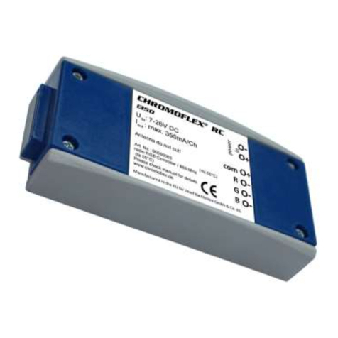
Barthelme CHROMOFLEX User manual

Chromoflex - Manual - English V1.07 - www.barthelme.de Rev. 19.08.2010
- 1 -
Full-Spectrum-Colour-Control
Chromoflex-Module V1.0 (Model „I350“) Infrared-Remote Control(s) (optionally)
Overview
ChromoFlex is an excellent value full colour control and was designed for use with modern High-
Power RGB LEDs. There are two models available „I350“ for use with constant current LEDs and
„STRIPE“ for use with LED stripes. ChromoFlex is able to generate 16 million different colours with 3
(optionally 4) channels. Hence it is the ideal control for all kinds of sophisticated effect illuminations,
deco and wellness lighting.
ChromoFlex is provided with several built-in effects (from calming colour change to show effects).
External manual buttons, DIP switches or PC software can be used to control the modules. Up to 30
modules can be connected in a network.
The complete network can be controlled by standard push-buttons or with an infrared remote control.
Usage
The modules were designed for indoor use in dry places. The LEDs might also be used in wet
environments or outdoors, if suited for that purpose.
Important: The modules must be operated with a power supply that is matched to the used LEDs!
Non-LED loads (especially inductive loads like motors, coils, etc) might destroy or damage the
module.

Chromoflex - Manual - English V1.07 - www.barthelme.de Rev. 19.08.2010
- 2 -
Safety Instructions
Safety Instructions
The modules might produce some heat. Care must be taken to provide unrestricted air ventilation.
Connecting the power in reverse polarity can destroy the module, even if connected for a short time
only. The built-in fuse can only be changed by soldering.
Important: It is guaranteed by design that the ChromoFlex modules will never generate any higher
voltage than the supply voltage. The module is the ideal solution for use in low-voltage areas, like
pools, steam baths, SPAs, ....
Electronics must not be modified. Observe the official regulations for electrical devices (like DIN, VDE,
EN), especially when LEDs are used in wet areas!
This product is not a toy, keep away from children!
We decline any liability, loss, or damage caused by improperly used modules! Guarantee is also lost
in such cases.
LEDs can get quite hot. We strongly recommend ensuring maximum operating temperature is not
exceeded, because this might reduce the expected life time of the LEDs significantly.
WARNING #1: LED light may have very high intensity even when dimmed. Some modern LEDs are
classified by the lasers marking obligation. Particularly in connection with optics also weak LEDs may
be very dangerous. Staring into LEDs may cause irreparable damage to the eye's retina. Hence:
NEVER STARE INTO THE BEAM. Use diffusers to spread the intensity!
WARNING #2: Please be aware that LED light may cause side effects. This light changes intensity
very fast! Changing light may affect the perception and is also known to trigger epileptic seizures in
persons who are photosensitive.
Contents
Each ChromoFlex is shipped with a short manual, a connector for power supply and a connector for
the network interface, and a short pigtail cable for connecting 4 external buttons. The connector cable
to a PC (RS232) is available as separate item or can be made easily by oneself (see software
documentation).
The Infrared-Remote Control plus receiver are optional accessories.
Software / further information
Several ChromoFlex modules can be linked in a network. A number of about 30 should be
unproblematic. The number of modules used can vary depending on cable length and cable type
used.

Chromoflex - Manual - English V1.07 - www.barthelme.de Rev. 19.08.2010
- 3 -
For programming the software „ChromoFlex Editor“ is free for download from our website (address at
the end of manual). A COM-port (RS232) or a standard USB/RS232 converter is required.
Connecting the LEDs / Power Supply
Important: The module must be operated with a power supply, that is suitable for the used LEDs!
Important: Matched LED lamps, including power supplies are available from stock. We also supply
complete kits, including plug-n-play connectors.
Important: Improper power supplies may lead to malfunctions and unwanted flickering effects or
overheating. We strongly recommend using high-quality (stabilised) switching power supplies!
One power supply can be used for several ChromoFlex modules in parallel, if the maximum output
power of the supply is observed.
The minimum voltage for correct operation is 7 Volts; maximum voltage is 24 Volts (+ 5%).
Model „I350“
This model has 3 lines of 350 mA each. The power supply must match the number of LEDs used in
series: most high-power LEDs for 350mA constant current require around 3 - 3.7 Volts, depending on
colour, type and manufacturer. Usually, green and blue LEDs require the highest voltages; the
forward voltage of red is usually lower. The „I350“ itself additionally requires about 0.5 Volts to
maintain line regulation.

Chromoflex - Manual - English V1.07 - www.barthelme.de Rev. 19.08.2010
- 4 -
Improper voltages will cause unnecessary heat in the module. For internal temperatures >= 80°C the
module will power off (reversible).
Constant current LEDs must be connected in series. Depending on the number of LEDs used the
recommended voltage for the power supply is (these are guidance values depending on the LEDs
used):
1 RGB-Group - abt. 7 - 7.5 Volt Power supply (abt. 7 Volt is the minimum operating voltage of
2 RGB-Groups - abt. 7.5 - 9 Volt Power supply electronics)
3 RGB-Groups - abt. 10 - 13 Volt Power supply
4 RGB-Groups - abt. 12 - 15 Volt Power supply
5 RGB-Groups - abt. 15 - 18 Volt Power supply
6 RGB-Groups - abt. 18 - 24 Volt Power supply
Power Supply
110/230V Inp.,
110/230V~
ChromoFlex-Module "I350"
LED1 LED2 LED3
R -
G -
B -
Common +
Power Supply +
Power Supply - (GND)
RS232-RX
RS232-GND
to PC
Common +
ca. 10-12V/1.2A
+
-
~
~ 10-12V/1.5A Outp.
The example above uses 3 LEDs. A 4-wire cable is used, in which one wire is a simple pass-through
for the common +.
ChromoFlex modules will not emit high frequency signals, even for longer lines. Unlike many
electronic transformers for halogen lamps cable lengths of 10 metres are unproblematic, if the
calculation above is considered
Hint: Copper has a resistance of about 0.02 Ohms per metre for a cable cross section of 1mm².
Power Supply
110/230V Inp.,
110/230V~
ChromoFlex-Module "I350"
LED1 LED2 LED3
R -
G -
B -
Common +
Power Supply +
Power Supply - (GND)
RS232-RX
RS232-GND
to PC
Common +
ca. 10-12V/1.2A
+
-
~
~ 10-12V/1.5A Outp.

Chromoflex - Manual - English V1.07 - www.barthelme.de Rev. 19.08.2010
- 5 -
Important: If the selected supply voltage is too low, the LEDs might not operate with maximum
brightness or some flickering can be noticed. Unnecessary heat must be dissipated if the supply
voltage is too high. Sets coming from our stock are already matched. When using other switching
supplies there is a small potentiometer on the supply, to adjust the output voltage within several
percent.
We recommend selecting the lowest voltage on which all LEDs perform at full brightness without any
disturbance.
The power supply must provide 1.2 Ampere maximum to each „I350“module (all channels on full).
Important note: The optimal operating voltage of the „I350“ module is 12 Volts using 3 industrial
standard 3*1 Watt RGB-LEDs in serial connection. The following considerations have been made with
regard to design:
yAt least 2 channels drive LEDs with higher forward voltage (green, blue)
yThe total continuous power dissipation in the module is <= 2.5 Watt, The module is not designed
to run continuously at full load (even mixed „white“ usually requires only 66% full load).
yGood air ventilation is needed, environment air temperature should be <= 30°C
We recommend reducing the dissipating heat in the module by using an external power resistor to
lead off excess power if these limits are exceeded for longer periods, especially when using more
than 3 LEDs in serial connection:
In the picture a low cost 5 Watt power resistor mounted
on an aluminium plate was used. Its value can be
calculated with the formula:
R = U / 0,35 and P = U * 0,35
(U is the surplus Voltage in Volts, R the resistance, P the
load the resistor will take). An example: If using 6 red
LEDs in series with a forward voltage of 6 * 2.8 Volts and
operating the module with 24 Volts, the resistor shall
catch 6 volts so that the electronics has about 2 volts
headroom for regulation. Hence the resistor should have
18 Ohms and 5 Watt maximum load.
Model „STRIPE“
This model does not have any internal current regulator. Supply voltage is passed through and the
voltage of the power supply must match the voltage of the LED stripe.
Regarding any possible voltage drop, please see the previous paragraph. Cable lengths up to 5
metres are allowed.
Note: LED stripes of 10 Volts, 12 Volts and 24 Volts are offered on the market.
Note: We also deliver flexible LED stripes on wheels in length of up to 4 metres. Each colour requires
up to 2 Amperes at 12 Volts.

Chromoflex - Manual - English V1.07 - www.barthelme.de Rev. 19.08.2010
- 6 -
The model „STRIPE“ is designed for currents up to 2.5 Ampere per channel (7.5 Ampere in total) at
an operating Voltage of 12 Volts. For 24 Volts maximum is 1.25 Ampere per channel.
First Test
Installation is very simple when using the connectors enclosed.
At first a test is performed on the module showing a standard colour change (this is the factory
default). This effect consists of 8 colours, holding 5 seconds each, colour transition time is 2.5
seconds.
At first a test is performed on the module showing a standard colour change (this is the factory
default). This effect consists of 8 colours, holding 5 seconds each, colour transition time is 2.5
seconds.
Diagnostic LED: The modules are equipped with a small LED. For regular operation this LED will
change every 2 seconds and flickers when data is transmitted over the bus.
Manual Buttons
Each ChromoFlex module is equipped with 4 inputs for buttons to select the effects:
Cable length for the buttons may be up to 10 metres. We recommend using shielded cables for
distances more than 1 metre, when operated in an electrically noisy environment. The shield should
be connected to SW-GND.
Note: It is also possible to use remote controls or relay switches instead of manual buttons.
Power Supply
110/230V Inp.,
110/230V~
ChromoFlex-Modul "STRIPE"
R -
G -
B -
Common +
Power Supply +
Power Supply - (GND)
RS232-RX
RS232-GND
to PC
12V/6A
+
-
~
~12V/6AOutp.
Red, LED-Stripe, i.e. 4 Mtrs, 2 Ampere
Green, LED-Stripe, i.e. 4 Mtrs, 2 Ampere
Blue, LED-Stripe, i.e.. 4 Mtr, 1.8 Ampere
Button 1
Button 2
Button 3
Button 4
SW-1
SW-2
SW-3
SW-4
SW-GND
ChromoFlex
Module
GND

Chromoflex - Manual - English V1.07 - www.barthelme.de Rev. 19.08.2010
- 7 -
Networking
Many ChromoFlex modules can be operated within a network. This means each module can either
send or receive data! Connectors for RS232-RX and RS232-GND are required.
It is a precondition for network operation that all modules of the network have a common GND with
the power supplies.
If a button is pressed on any module, it will pass this command to all other modules connected over
the network as factory default.
Note: the data transmission protocol is based on a mathematical algorithm that is very robust against
transmission errors.
Important: For correct operation it is required to add a resistor of around 10 kOhms (Low Cost) to the
bus. This resistor is included in the PC adapter kit delivered from stock. A shielded low frequency
cable is very well suited for network lines. For short networks (< 5 metres) an unshielded cable is also
suitable. The 10 kOhms resistor should be connected between RS232-RX and RS232-GND
somewhere in the network, from where the signals are sent to the PC. The connection from module to
module requires only RS232-RX and the common GND.
LEDs
Pwr+
Pwr- (GND)
RS232-RX
RS232-GND
LEDs
Pwr+
Pwr- (GND)
RS232-RX
RS232-GND
LEDs
Pwr+
Pwr- (GND)
RS232-RX
RS232-GND
10k
to PC
optionally
Buttons
Buttons
Buttons
to Power Supply
to Power Supply
to Power Supply.
optionally Button
s
to LEDs/Stripes
to LEDs/Stripes
to LEDs/Stripes
optionally Buttons
optionally Buttons

Chromoflex - Manual - English V1.07 - www.barthelme.de Rev. 19.08.2010
- 8 -
In the examples above 3 modules build a network. Please note: the module interconnection are 2
lines: GND and RS232-RX.
Factory pre-programmed Effects
Each module is shipped with 8 factory pre-programmed effects:
Effect 1: Standard colour change, colour change each 5-60 seconds (depending on the
internal DIP switches). Colour transition time: 2.5 seconds
Effect 2: Slow (very soft) colour change each 30-180 seconds (depending on the
internal DIP switches). Colour transition time: 10 seconds
Effect 3: Randomly faded colours „Blob“
Effect 4: User defined-colour change (can be changed by the „Chromoflex
Editor“ software for PC, default is red-green-blue)
Effect 5: Randomly changed colours „LSD“
Effect 6: Simulation of a fire „Fire“
Effect 7: Simulation of a thunderstorm with lightning („Flash“)
Effect 8: Randomly coloured flashes („Burst“)
If you would like to edit your own colour change, this can be done very easily with our free software of
PC „Chromoflex Editor“. This software can be downloaded for free from our website (see end of this
manual).
Note: The ChromoFlex modules are based on a programmable microprocessor that is also capable of
performing other complex tasks. We will be happy to realise your ideas for professional products. Do
not hesitate to send us an E-Mail.
The 8 effects can be selected by 4 buttons. Each button selects two effects:
Button 1: 1. Pushed once: effect 1 (normal colour change)
2. Pushed twice: effect 5: „LSD“
Button 2: 1. Pushed once: effect 2 (Soft colour change)
LEDs
Pwr+
Pwr- (GND)
RS232-RX
RS232-GND
LEDs
Pwr+
Pwr- (GND)
RS232-RX
RS232-GND
LEDs
Pwr+
Pwr- (GND)
RS232-RX
RS232-GND
10k
to PC
optionally
Buttons
Buttons
Buttons
to Power Supply
to Power Supply
to Power Supply.
optionally Button
s
to LEDs/Stripes
to LEDs/Stripes
to LEDs/Stripes
optionally Buttons
optionally Buttons

Chromoflex - Manual - English V1.07 - www.barthelme.de Rev. 19.08.2010
- 9 -
2. Pushed twice: effect 6: Fire „Fire“
Button 3: 1. Pushed once: effect 3: „Blob“
2. Pushed twice: effect 7: Lightning „Flash“
Button 4: 1. Pushed once: effect 4: User colour change
2. Pushed twice: effect 8: „Burst“
Button 1: 1. Pushed once: effect 1 (normal colour change)
2. Pushed twice: effect 5: „LSD“
Button 2: 1. Pushed once: effect 2 (Soft colour change)
2. Pushed twice: effect 6: Fire „Fire“
Button 3: 1. Pushed once: effect 3: „Blob“
2. Pushed twice: effect 7: Lightning „Flash“
Button 4: 1. Pushed once: effect 4: User colour change
2. Pushed twice: effect 8: „Burst“
Important! Shutdown: if any button is pressed longer than about 3 seconds, all modules are switched
off; any other button will start its assigned effects.
The DIP-Switches - Default-Effects
Some settings (i.e. the default effect after reset or power on) can be preset with the internal DIP
switches. In this case the cover of the module must be opened (see attachment).
Important: Please do not touch any of the electronic components, because of the risk of damage by
electrostatic discharge. We recommend using a small non-conductive tool to change the DIP
switches.
The switches are separated in 3 groups (as imprinted):
DIP 1, 2: These two switches control hold time for effects 1 and 2 (colour changes):
DIP 1 DIP 2 Effect 1 Effect 2
Off Off 5 sec. 30 sec. (default)
On Off 10 sec. 60 sec.
Off On 30 sec. 120 sec.
On On 90 sec. 180 sec.
DIP 3, 4, 5: These switches are for the default effect after reset or power on.
DIP 3 DIP 4 DIP 5 Effect
Off Off Off Effect 1: Standard colour change, colour transition time 2.5 seconds (default)
On Off Off Effect 2: Slow colour change, colour transition time 10 seconds (default)
Off On Off Effect 3: Randomly faded colours „Blob“
On On Off Effect 4: User defined colour change (can by changed by PC software
Off Off On Effect 5: Randomly changed colours „LSD“
On Off On Effect 6: Simulation Fire „Fire“
Off On On Effect 7: Simulation Lightning („Flash“)
On On On Effect 8: Randomly coloured flashes („Burst“)
DIP 6, 7, 8 determine the „Group“ of a module. Because the modules can be connected as a network,
it should also be possible to send commands only to a part of the network. This is what we call a
„Group“. For example, if several modules are used for a pool illumination (ceiling, walls under-water)
these modules could be separated into three groups. Now it is possible to send commands i.e. only to
the modules on the ceiling. More information can be found in the following paragraph „A Pool
Scenario“..

Chromoflex - Manual - English V1.07 - www.barthelme.de Rev. 19.08.2010
- 10 -
Another important use of the Groups is the starting colour for the pre-programmed colour changes
after power on or reset: To achieve impressive effects - even without using a network or PC software -
the Groups can be used. Seven different starting colours are available:
DIP 6 DIP 7 DIP 8 Group Starting colour Index of starting colours
Off Off Off (none) Red 1 (Default)
On Off Off Group 1 Green 4
Off On Off Group 2 Blue 7
On On Off Group 3 Magenta 8
Off Off On Group 4 Orange 2
On Off On Group 5 Light Blue 6
Off On On Group 6 Yellow 3
On On On Group 7 Red 1
Note: The colour „indigo“ ,index 5, is not available by design.
Important: All changes of the DIP switches are identified after reset or power on!
Colour Tables - „Cold- and Warm Colours“
Note about the indices of the starting colours: The ChromoFlex modules generate the colours by look-
up tables. These tables can be changed by the PC software „ChromoFlex Editor“. It is simple to
remove i.e. all „cold“colours from the colour maps (or vice versa). Removing unwanted colours is also
possible (keyword „corporate colours“).
These effects use the colour tables (2 are available):
Effect 1: Standard colour change (table 1)
Effect 2: Slow (soft) colour change each 30-180 Seconds (table 1)
Effect 3: Randomly faded colours „Blob“ (table 1)
Effect 4: User colour change (default is red-green-blue, table 2)
Effect 5: Randomly changed colours „LSD“ ( table 1)
Effect 8: Randomly coloured flashes („Burst“) (table 1)
Infrared-Remote-Control - Installation
For controlling one or more modules (connected as a network) an infrared control can be used. Only
one single module within a network should be equipped with an infrared receiver. The receiving
module will forward any received commands to the network.
Important: If there is more than one infrared
receiver in use communication problems may
occur. It is only acceptable to use more than one
receiver when the receivers are totally
independent (i.e. if located in different rooms).
Important: In some rare cases other devices
(TV, Video ...) might react to the ChromoFlex
infrared control (or vice versa). In such cases
please separate the optical paths.

Chromoflex - Manual - English V1.07 - www.barthelme.de Rev. 19.08.2010
- 11 -
Chromoflex module with (plugged) receiver Module with extended cable (abt. 20 cm)
The cables for the infrared receiver can be extended from 20 to 100 cm. Shielded cables are
recommended with lengths of more than 20 cm. The shield can be connected to the free pin of the
receiver’s socket. If touching electronic parts, please observe the common known handling
instructions for electrostatic sensitive devices (ESD). Please discharge yourself.
Important: If polarity of the infrared receiver is reversed, receiver and ChromoFlex module can be
damaged!
Important: If polarity of the infrared receiver is reversed, receiver and ChromoFlex module can be
damaged!
Infrared-Remote-Control – Operating
A precondition is that an infrared receiver is connected to the ChromoFlex module.
See chapter above. The 4 large buttons on the remote control are equivalent to the
4 „standard“ buttons
Upper Channel +button is button 1,
Right Volume + button is button 2,
Lower Channel button„-’ is button 3,
Left Volume - button is button 4.
The crossed out earphone button is Learn-Mode.
Programme-Mode
8 pre-programmed Effects are available.
Button 1: 1. Pushed once: effect 1 (normal colour change)
2. Pushed twice: effect 5: „LSD“
Button 2: 1. Pushed once: effect 2 (Soft colour change)
2. Pushed twice: effect 6: Fire „Fire“
Button 3: 1. Pushed once: effect 3: „Blob“
2. Pushed twice: effect 7: Lightning „Flash“
Button 4: 1. Pushed once: effect 4: User colour change
2. Pushed twice: effect 8: „Burst“

Chromoflex - Manual - English V1.07 - www.barthelme.de Rev. 19.08.2010
- 12 -
In Learn-Mode single colours can be mixed or dimmed individually.
Push Learn button: the actual setting freezes when a colour change is running. Then every single
colour can be dimmed.
Select the colour by pushing button 2 or 4 for a longer time. The colour flashes when the button is
pushed. The colours can be scrolled by pushing the button again. Now the selected colour or intensity
of the lights is dimmable with button 1 and 3 and it can be varied in 7 steps. To return to Dim-Mode,
switch off the unit with On/Off-button.
The selected colour or intensity is lost when you turn off the unit.
Hint: Try to set up the colour „white“: White consists of 100% green and about 30-50% of Red and
Blue (depending on the used LEDs).
A Pool-Scenario
In this last paragraph we will describe a small „real world“ example:
Let’s assume you would like to illuminate a pool with several Chromoflex modules, but without using
any PC software or network:
The lamps are separated into 3 groups:
Group „Under-Water“: Start with „Blue“ as first colour.
Group „Walls“ Start with „Green“
Group „Ceiling“ Start with „Red“.
Group „Under-Water“: Start with „Blue“ as first colour.
Group „Walls“ Start with „Green“
Group „Ceiling“ Start with „Red“.
The colours should change slowly and each colour should be held for 2 minutes. All modules should
transit to the next colour simultaneously.
This task is easy to perform:
1.) Because each Chromoflex contains a precise „Quartz crystal oscillator“, all modules run quite
synchronously after reset or power on. The deviation between the modules is only a few seconds per
day. Normally a pool illumination does not run continuously, hence the power-on is sufficient for
synchronisation.
2.) All modules are set to effect 2 (slow colour change) with a holding time of 120 sec per colour.
3.) The starting colour is determined by the group:
As a result these are the settings for the DIP switches:
DIP 1 DIP 2 DIP 3 DIP 4 DIP 5 DIP 6 DIP 7 DIP 8 Group
Off On On Off Off Off On Off „Under-Water“
Off On On Off Off On Off Off „Walls“
Off On On Off Off On On On „Ceiling“
It is that easy!
Software 1 - 2 - 3
1.) We offer the „Chromoflex Editor“ for free-download from our website. The software contains
additional documentation, not covered by this manual.
2.) We are planning to publish drivers for all common PC programming languages, so that any
interested user is able to integrate the Chromoflex in their own software.

Chromoflex - Manual - English V1.07 - www.barthelme.de Rev. 19.08.2010
- 13 -
3.) For interested professional users, we can help in implementing access to the Chromoflex from
own „embedded controls“. Our development team has considerable experience in all kind of
embedded developments.
Random Effects
Each Chromoflex module can generate individual random effects. Because the random coincidence is
based on a mathematical calculation, only modules with different serial numbers appear truly
different. Depending on production output this might require that the user once initialises each module
with an individual serial number (or else all modules run the same „random sequence“). Generating
an individual serial number is described in the manual for the PC-software „Chromoflex Editor“.
Technical Data
Technical Data
Operating Voltage: 7 - 24 Volt (+ 5%), stabilised.
Important: The power supply used must be able to bear pulsed loads. Unstabilised or too weak power
supplies can cause unwanted flickering effects, especially during colour changes!
Module current (without LED lamps): ca. 20 mA
Operating temperature: 0°C - max. +50°C (recommended: <= 30°C) (Use only in dry places with
sufficient air ventilation)
Modulation system: The Chromoflex modules are based on a digital System, called „Vector-Fractal-
Modulation“ or „VFM“. This modulation system was optimised for minimising load on power supplies
and has considerable advantages compared to traditional systems. The modulation frequency is in
the range from 120 Hz up to (max.) 240 Hz. Patent pending.
Maximum cable inductance can be calculated as L_max = 40µH (maximum current). Note: Standard
control cable normally has an inductance of around 0.4-0.8 µH/m.
Model „I350“
Pulsed constant current abt. 350 mA (+ 5%, -20%) per channel (3 channels).
Model „Stripe“
Pulsed constant voltage, maximum current 2.5 Ampere per channel (3 channels) at 12 Volts, and 1.25
Ampere per channel at 24 Volts.
Contact / Internet
Download of PC-Software, data sheets , technical support:
www.chromoflex.com , www.barthelme.de
Contact (technical support only by Internet / Email):

Chromoflex - Manual - English V1.07 - www.barthelme.de Rev. 19.08.2010
- 14 -
www.barthelme.de

Chromoflex - Manual - English V1.07 - www.barthelme.de Rev. 19.08.2010
- 15 -
Attachment - Module Pinout:
Table of contents
Other Barthelme Control Unit manuals
Popular Control Unit manuals by other brands
Van Lien
Van Lien IR-CU instruction manual
Emerson
Emerson Neotecha Sapro Operating and safety instructions
Wilo
Wilo Control SC-L Installation and operating instructions
LIFE home integration
LIFE home integration ACER RG1R UNI DL Instructions and warnings for installation, use and maintenance
Midland
Midland A-1075 Installation, operation & maintenance manual

WAGO
WAGO I/O-SYSTEM 751-3002 manual
iNels
iNels CU3-01M manual

tau
tau DC18 installation guide
LIFE home integration
LIFE home integration GENIUS GE 224 Instructions and indications for installation, use and maintenance
Definox
Definox Sorio Maintenance notice
Puls
Puls DIMENSION YR40.245 manual

Rohl
Rohl Riobel PERRIN ROWE R46 instruction manual
