HORITA SCT-50 User manual

HORITA SCT-50
Serial Control Titler
USER MANUAL
For Models SCT-50, RM-50/SCT, SR-50/SCT
Doc. 071550
Rev. D
(C) Copyright 2014
P.O. Box 3993, Mission Viejo, CA 92690 (949) 489-0240 www.horit .com

2
COPYRIGHT
(C) 2014 HORITA CO., INC. All rights reserved
No part of this document may be copied or reproduced in any form or by any means without prior written
consent of HORITA CO., INC, P.O. Box 3993, Mission Viejo, CA 92690.
HORITA CO., INC makes no warranties with respect to this documentation and disclaims any warranties of
merchantability or fitness of the SCT-50 for a particular purpose or application.
HORITA, its logo, SCT-50, and GMAN, are trademarks of HORITA CO., INC.

3
1 GENERAL CHAPTER 1
2 FEATURES CHAPTER 2
2.1 SCT-50 Umit 4
2.2 SCT-50 GMAN Software 5
3 CONNECTING CHAPTER 3
Figure 3.1, SCT-50 Serial Port Wiring 6
4 OPERATING CHAPTER 4
4.1 Power Up 6
4.2 Mode Flow Diagram Explanation 7
Figure 4-1, SCT-50 Mode Flow Diagram 7
4.3 LED Operation 7
4.4 Entering and Exiting the Setup Menus 7
4.5 Selecting Different Setup Menu Items 8
4.6 Changing the Selected Menu Item 8
4.7 SYSTEM SETUP Menu 8
4.8 DISPLAY SETUP Menu 9
4.9 TIME SETUP Menu 10
Table 4-1, Time Display Formats 11
4.10 DATE SETUP Menu 11
Table 4-2, Date Display Formats 12
4.11 Selecting Local Titling Mode and Entering 12
and Editing Data
4.12 Character Selection 12
Table 4-3, Character Set 13
4.13 Inserting Spaces and Deleting Characters 14
4.14 Centering a Line of Text 14
4.15 Turning the Display Off and On 14
4.16 Split Screen Display 14
4.17 Operating The SCT-50 using the GMAN 14
Software Program
4.18 Setting the SCT-50 Address 14
4.19 Serial Communications Check 15
5 SERIAL COMMUNICATIONS CHAPTER 5
5.1 Serial Communications Method 15
5.2 Broadcast And Promiscuous Modes 15
5.3 Single Function Commands 15
5.4 Function/Data Commands 15
5.5 Serial Command Set 16
5.6 Character Set and ASCII Codes 17
5.7 Serial Communications Example 17
5.8 Software Programming Examples 18
6 MAINTENANCE CHAPTER 6
6.1 Cleaning 18
6.2 Service and Troubleshooting 18
6.3 Adjustments 18
Figure 6-1, Adjustment Locations 19
6.4 Horizontal Size Adjustment 19
6.5 Video Level & Equalization Adjustment 19
7 SPECIFICATIONS CHAPTER 7

4
1
GENERAL
The SCT-50 is a video character generator that operates either stand alone or with a computer to title, caption, or time-date stamp
NTSC or PAL composite video images from TV cameras, video recorders, computers, etc.
The SCT-50 can insert up to nine lines of twenty characters each into the video image to add source ID information such as camera
number and location for security applications, add measurement data during video data collection, or to simply add text in other
video monitoring and display situations.
The SCT-50 operates stand alone via operation of front panel switches but can also be used with a computer and the supplied
HORITA GMAN text editor and control software programs to provide complete computerized and automated remote control of
one or more SCT-50's.
The GMAN software greatly simplifies the use of multiple SCT-50's to operate complex video information displays, add
instructional information or subtitling, log and document experiments, etc.
The GMAN software program can control from 1 to 99 SCT-50s using only a single RS-232 PC comm port on the computer. The
GMAN program stores up to 100 individual SCT-50 screens of text and setup information, any of which can quickly be selected
and sent to individual, groups, or to all SCT-50 units. The sending of data to the SCT-50's can be done manually or can be
automated to occur at timed intervals.
Note that a computer USB port can be used for communication with the SCT-50 with the use of a "USB-to-Serial" adapter cable.
These cables are available online (Amazon.com) or from computer stores. There are many manufacturers. A well known
manufacturer is "Belkin".
The SCT-50 can also be computer controlled using software programs written by the user in "C", "BASIC" ("Visual" or
otherwise), or other computer languages as desired.
2
FEATURES
2.1 SCT-50 UNIT
•Inserts up to nine lines of twenty characters each of text and graphic symbols, plus time and date.
•Operates stand alone via front panel switches or can be controlled by the included Windows-based Group Management
software program called HORITA GMAN.
•Selectable character attributes for white or black characters, background on/off, contrast, size, position, etc.
•The nine lines of text can be automatically numbered and then un-numbered to assist in placement of text over the video
image.
•Five separate onscreen setup menus titled System, Display, Time, Date, and Help, plus hardware and software system reset
functions provide quick and easy setup of an SCT-50 via the front panel switches.
•Unique vertical "split-screen" mode displays text on only top and bottom of screen, leaving center of image uncluttered. The 9
lines of text are split into 5 lines at the top and 4 lines at the bottom of the screen. The amount of split is continuously
adjustable and can be set so that the top most line of text can be positioned within the vertical interval, with the very next top
and bottom lines then generally visible only on a monitor that has underscan.
•Internal crystal controlled clock/calendar has battery back up to maintain time and date when unit is powered off.
•Thirty-six time display formats (24 hour military, AM/PM, etc.) and sixty date display formats, including those which
automatically calculate and display the day of the week., offer maximum flexibility for displaying time and date.
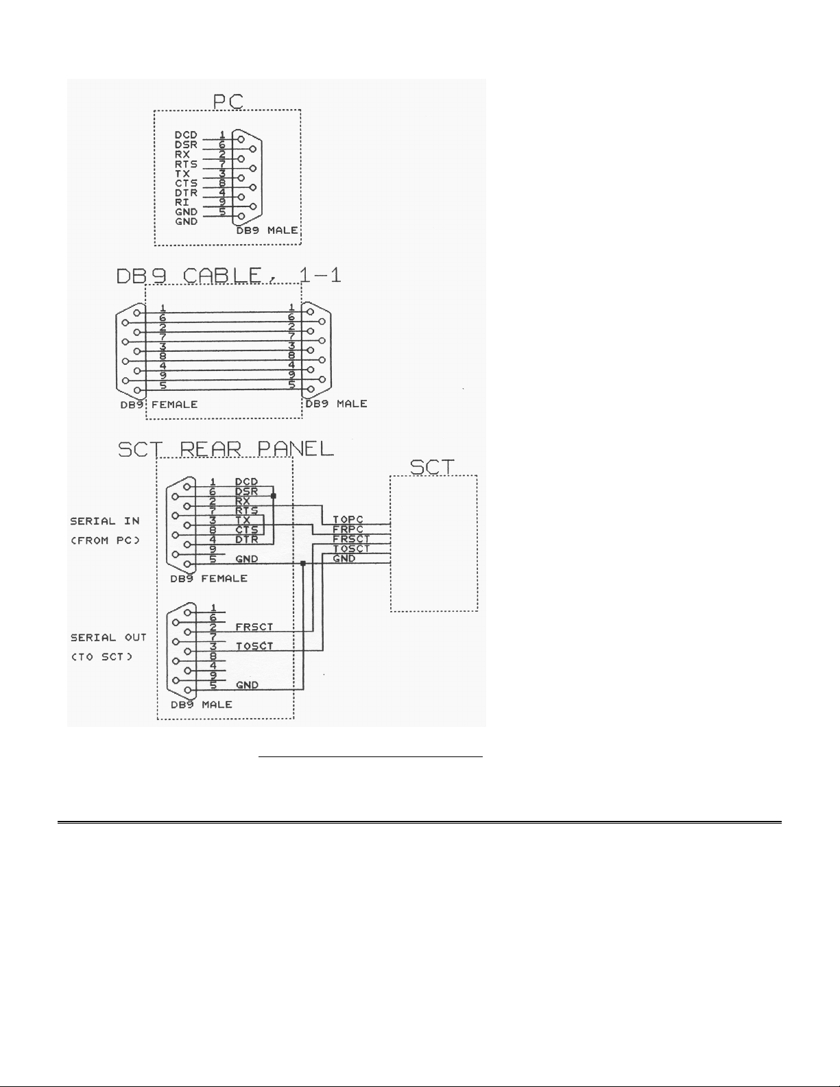
•Standard DB-9 connectors for serial port operation with RS-232 loop thru allows up to 99 SCT-50 units to be daisy chained

5
together and individually or group addressed by the GMAN.EXE program.
•When computer controlled, individual SCT-50 units can have their own unique address or can be set to respond to and display
text sent to any SCT-50 unit in the chain.
•Three baud rates available for serial port operation; 4800, 9600, or 38.4K baud.
2.2 SCT-50 GMAN SOFTWARE
•The Windows-based GMAN text editor and control program works with from 1-to-99 SCT-50 units, individually or in groups.
•Individual SCT-50 units can have names assigned to them, rather than just a number from 01 to 99. These names can then be
automatically sent to all of the SCT-50's and displayed on the associated video monitor video monitor for a quick visual ID.
After the ID is complete, the names can be automatically removed and the previous text restored.
•Three send modes for communicating with SCT-50 units provide manual, end-of-line, or continuous send operation.
Continuous send provides real time positioning of text within the video image.
•Simple to use but feature rich text editor creates, saves, and opens up to 100 9X20 screens of text. Each screen faithfully
shows what will be displayed on an SCT-50 and can be assigned to an individual SCT-50 or group of SCT-50 units.
•The text editor provides typical search, justification, page scrolling, cut, copy, paste, etc., functions that operate on individual
pages of text as well as groups of pages.
•SCT-50 control functions, such as character attributes, can be sent to an individual SCT-50 or to groups of SCT-50 units.
•Complete control of all SCT-50 time and date functions is provided. The on screen position as well as all of the various time
and date display formats provided by an SCT-50 are also replicated on the text editor screen whenever the SCT-50 time and/or
date display format is displayed.
•Full and thorough "Help" manual is indexed and searchable, printable in its entirety, and also printable as a .PDF file.
•The "effects" functions provided by the GMAN software include various automated operations such as random movement of
onscreen text, timed turning on and off of various lines of text, and timed sending of pages of text to SCT-50 units. An
additional feature is the ability to operate in a "loop" mode and continuously repeat the timed sending of a sequence of pages
of text to the SCT-50 units.
3
CONNECTING
1. Connect a source of composite video to the SCT-50 VIDEO IN. This input is looped to the output when power is OFF,
terminated when power is ON.
2. Connect the SCT-50 VIDEO OUT to a video monitor, recorder, or other video device.
3. If using computer control, connect the SCT-50 SERIAL IN DB9 connector to the desired RS-232 COMM serial port on the PC.
You can use any standard male-to-female, one-to-one DB9 cable
4. If you are connecting more than one SCT-50 to the serial port, use another DB9 cable to connect between units. You can also
purchase special extra short 1' DB9 SCT-50 cables from HORITA. Routing of the serial cables to and between the SCT-50
units themselves can be in any order.
5. Connect power to the SCT-50 using the 9-Volt, 500mA power adapter supplied.

6
Figure 3-1, SCT-50 Serial Port Wiring
4
OPERATING
4.1 Power Up
To operate the SCT-50, apply power and set the SCT-50 POWER switch to ON. A red LED above the power switch lights when
the SCT-50 is powered up.
When the SCT-50 is initially powered up, it operates in the "display" mode to display the time and date and any user source ID
information entered. The POSITION and CHAR switches operate to provide quick and convenient control of the display's
horizontal and vertical position, without going through any "menu" operations.

7
The SCT-50 can be operated locally using the front panel switches or from both the switches and the PC to enter text and setup
information. Operation is first described for entering and changing "setup" data, then entering and editing text using the SCT-50
front panel switches. Operation with the GMAN software is described in the GMAN manual provided within the GMAN software.
4.2 Mode Flow Diagram Explanation
Figure 4-1 shows how the SCT-50 modes change as the MODE switch is actuated between TITLE and SETUP
UP arrow = TITLE
DOWN arrow = SETUP
Insert/Del Spaces
Enter Title Information
Title Display OFF (DOWN arrow)
Title Display ON
Setup Menu Display ON
(Auto return to SETUP display)
Next SETUP Menu
Figure 4-1, SCT-50 Mode Flow Diagram
As previously stated, when first powered up, the SCT-50 enters the Display mode. Actuating the MODE switch to SETUP causes
the SCT-50 to enter the Setup mode and display the same Setup Menu and Item that was displayed before the SCT-50 was last
powered down. Further actuating of the MODE switch to SETUP causes the SCT-50 to cycle through its five setup menus.
Actuating the MODE switch to TITLE when in Setup mode causes the SCT-50 to enter the Display mode. Further actuation causes
the SCT-50 to turn the display off, enter the titling mode, and finally enter the insert/delete text mode.
4.3 LED Operation
The front panel LED blinks at different rates to provide indication of SCT-50 operation.
LED Condition Meaning
Off Power off
Steady on Setup/Display On/Off modes
Very slow blink, 1-sec. on/off No video
Slow blink, .5-sec. on/off Data entry mode
Fast blink, .25-sec. on/off Insert data mode
Fast flash on/off Receiving serial data
4.4 Entering and Exiting the Setup Menus
The setup menus allow selection of various character attributes such as black or white characters, character size, time and date
display formats, etc. Some selections, for example black or white characters, affect the setup menu display so you can see their
immediate effect. Other selections, for example character size, display their effect after the setup menu is exited.
To display the setup menus, toggle the MODE switch to SETUP and release. Depending on the actual mode that the SCT-50 is
operating in, you may have to toggle the switch several times to enter a setup menu.

8
The selected item on the setup menu is indicated by its "flashing" on and off. In setup mode, the POSITION and CHAR switches
serve to select and change menu items.
To exit the setup mode, actuate the MODE switch to TITLE and release.
4.5 Selecting Different Setup Menu Items
Menu items are selected via the POSITION switch. Flashing of the menu selection moves on to the next item each time the
POSITION switch is actuated and released. Actuating the switch down causes the selection to move to the right and down,
actuating the switch up causes the reverse action. Holding the POSITION switch actuated causes quick scanning through the menu
items.
4.6 Changing the Selected Menu Item
After a menu item is selected, the choices available for that item are accessed via the CHAR switch. Actuating the CHAR switch
down or up scans forward or backward through the choices available. Holding the switch actuated causes automatic scanning
through the choices. The setup menu items, functions, and selections available are described for each of the setup menus in the
following paragraphs.
4.7 SYSTEM SETUP Menu
A typical SYSTEM SETUP menu appears on the SCT-50 screen as follows:
*SYSTEM SETUP*
ONLINE Y
ADDRESS 00
MODE NOR
BAUD 9600
SYSTEM RESET N
VER SCT334 NTSC Y
The following paragraphs provide a detailed explanation of each of the SYSTEM SETUP menu items.
ITEM FUNCTION SELECTIONS
ONLINE Enables/disables Y = Enable communications
serial communications N = Disable communications
with PC
ADDRESS Assigns unique address 00 - 99
to SCT-50 for serial
communications with PC.
Note that setting the SCT-50 address to "00" places it in the "promiscuous" mode which enables it to respond to all information
sent via the serial port from the computer, ignoring any specific SCT-50 address.
MODE Places SCT-50 into normal or NOR = Normal SCT-50 operation
"hex" mode of operation. Hex HEX = SCT-50 displays hexadecimal
mode is useful for debugging value of all serial data received from
computer programs being the computer to control the SCT-50.
developed to control the SCT-50
BAUD Set baud rate of serial 4800, 9600, 38.4K. Note that
communications. the actual communications rate at
38.4K baud rate should not be greater
than one byte per millisecond or the
SCT- 50 will miss serial characters.

9
cont.
ITEM FUNCTION SELECTIONS
SYSTEM RESET Y = Reset SCT-50 system
System reset initializes all variable data in the SCT-50 to default values. A hardware selected SYSTEM RESET function is
accessible by powering up the SCT-50 while holding the MODE switch in the "SETUP" position, then releasing it.
NTSC/PAL Selects video standard NTSC = Y = USA 525/60
for SCT-50 video display PAL = Y = Euro 625/50
vertical positioning.
4.8 DISPLAY SETUP Menu
A typical DISPLAY SETUP menu appears on the SCT-50 screen as follows:
*DISPLAY SETUP*
CHAR = WHT BACK= ON
CONT = HI FLSH = OFF
SIZE = H = 1X V = 2X
POSITION H = 17 V = 01
PAGE NUMBER 1
NUMBER LINES 1-9: N
CLEAR PAGE N
The following paragraphs provide a detailed explanation of each of the DISPLAY SETUP menu items.
ITEM FUNCTION SELECTIONS
CHAR Selects character “color”. WHT = white characters
BLK = black characters
BACK Selects character ON = background is on
background. OFF = background is off
SIZE Character Horizontal
and Vertical size.
H (Horizontal) 1X = 1 time (1.0 H pixels)
2X = 2 times (2.0 H pixels)
3X = 3 times (3.0 H pixels)
4X = 4 times (4.0 H pixels)
V (Vertical) 1X = 1 time (7 H lines)
2X = 2 times (14 H lines)
3X = 3 times (28 H lines)
4X = 4 times (42 H lines)
POSITION H (Horizontal) display 01-64 numerical reference.
position
V (Vertical) display 01-64 numerical reference, for
position vertical sizes 1X,2X,3X,4X.
00-80 numerical reference, for
vertical size 1S, 00-40 for
vertical size 2S.
The H and V position value controls the horizontal and vertical position of entire matrix of 9 lines of 20 characters each.
PAGE Selects one of two 1 = page 1 display and
NUMBER screen memory pages attributes.
for display, reading, 2 = page 2 display and

10
cont.
ITEM FUNCTION SELECTIONS
writing, and selects all attributes.
associated attributes.
Note that there are two independent display screens but with common time and date and attribute setup information.
NUMBER Number lines on display Y = Add line numbers
LINES 1-9 with numbers 1 -9 on N = Remove line numbers
left side of screen.
Numbering of the lines is used to help adjust H and V position and size and locate where to place text or the time and date on the
screen. Automatically numbers the lines with 1-9 at the left side of the display when "Y" is selected. The numbers are
automatically removed when "N" is selected
CLEAR PAGE Clear memory page and Y = Perform clear function
screen of all text page
and screen of all text.
4.9 TIME SETUP Menu
A typical TIME SETUP menu appears on the SCT-50 screen as follows:
*TIME SETUP*
TIME HH:MM:SS
DISPLAY ON
START POSITION 130
FORMAT 05
09:30:21 AM
The following paragraphs provide a detailed explanation of each of the TIME SETUP menu items.
ITEM FUNCTION SELECTIONS
TIME Unformatted time HH:MM:SS
display HH = 00-99 Hours
MM = 00-59 Minutes
SS = 00-59 Seconds
Displays current hours, minutes, and seconds value of internal real time clock and allows value to be changed. The TIME value
can be accessed for setting by using the POSITION switch to move the cursor up the screen into the desired HH, MM, or SS fields.
DISPLAY Turns display ON = display ON
ON and OFF OFF = display OFF
START Starting character position 001-180 001 is upper left
POSITION of formatted Time display hand corner of screen, 180 is
lower right hand corner.
When the starting position of the time display is changed via actuating the CHAR switch while the "START POSITION" menu
item is selected, the SCT-50 temporarily exits the TIME SETUP menu to show the display screen. Further actuation of the CHAR
switch moves the position of the time display on a character by character basis in a serpentine fashion so that you can observe its
actual position within your normal video display.
There are 20 character positions available on each of the 9 lines. Character "001" is located at the upper left of the screen;
character "180" is located at the lower right of the screen. It is also helpful to use the "NUMBER LINES 1-9" function to help see
where the time is displayed as its starting position on the screen is changed. Even though the time display "erases" any text that
was on the screen as it is moved, the text can be restored simply by actuating the MODE switch to SETUP, then back to TITLE.
After two seconds of no change in position, the display returns to the TIME SETUP menu.

11
cont.
ITEM FUNCTION SELECTIONS
FORMAT Selects format for displaying 01-36 - one of 36 Time
the time. display formats.
Table 4.1 shows the first 9 time display formats which use a colon ":" as the separator character. After the first nine formats the
basic pattern repeats but with different separator characters between the time digits. The time displayed right below the FORMAT
selection line shows how the selected format for the time display appears.
FORMAT # DISPLAY MEANING
01 13:02 24 hour H:M
02 13:02:36 24 hour H:M:S
03 13:02:36.7 24 hour H:M:S.1S
04 1:02 PM 12 hour H:M AM/PM
05 1:02:36 PM 12 hour H:M:S AM/PM
06 1:02:36.7 PM 12 hour H:M:S.1S AM/PM
07 02:36.7 No hours M:S.1S
08 27:24 1/2 H:S 1/2 hour downcounter
09 57:24 H:S 1 hour downcounter
10-to-18 Period "." separator.
19-to-27 Blank (transparent) separator.
28-to-36 No separator except for a
period whenever tenth of a
second is displayed.
Table 4-1, Time Display Formats
4.10 DATE SETUP Menu
A typical DATE SETUP menu appears on the SCT-50 screen as follows:
*DATE SETUP*
DATE MM-DD-YY
DISPLAY ON
START POSITION 140
FORMAT 05
JAN 6/1999
The following paragraphs provide an explanation of each of the DATE SETUP menu items.
ITEM FUNCTION SELECTIONS
DATE Unformatted date MM-DD-YY
display MM = 00-12 Months
DD = 00-31 Days
YY = 00-99 Years
Displays current month, day, and year value of internal calendar and allows value to be changed. The DATE value can be
accessed for setting by using the POSITION switch to move the cursor up the screen into the DATE MM-DD-YY year fields.
DISPLAY Turns display ON = display ON
ON and OFF OFF = display OFF
START Starting character position 001-180 001 is upper left
POSITION of formatted Date display hand corner of screen, 180 is
lower right hand corner.
When the starting position of the date display is changed via actuating the CHAR switch while the "START POSITION" menu
item is selected, the SCT-50 temporarily exits the DATE SETUP menu to show the display screen. Further actuation of the CHAR

12
switch moves the position of the date display on a character by character basis in a serpentine fashion so that you can observe its
actual position within your normal video display.
There are 20 character positions available on each of the 9 lines. Character "001" is located at the upper left of the screen;
character "180" is located at the lower right of the screen. It is also helpful to use the "NUMBER LINES 1-9" function to help see
where the date is displayed as its starting position on the screen is changed. Even though the date display "erases" any text that was
on the screen as it is moved, the text can be restored simply by actuating the MODE switch to SETUP, then back to TITLE.
After two seconds of no change in position, the display returns to the DATE SETUP menu.
ITEM FUNCTION SELECTIONS
FORMAT Selects format for 01-60 selects one of 60
Date display formats for displaying the date.
The following nomenclature is used to describe the date format:
ITEM MEANING VALUE RANGE
mm numeric month value (01-12)
dd numeric day value (01-31)
yy numeric year value (00-99)
cc numeric century value (19-20)
MMM month abbrv. (JAN,FEB,MAR,etc.)
DAY day-of-week abbrv. (SUN,MON,TUE,etc.)
Table 4-2 shows the first 12 date display formats which use a slash "/" as the separator character. After the first twelve formats the
basic pattern repeats but with different separator characters between the date digits. The date displayed right below the FORMAT
selection line shows how the selected format for the date display appears.
FORMAT # DISPLAY
01 mm/dd
02 mm/yy
03 mm/dd/yy
04 MMM/dd/yy
05 MMM/dd/ccyy
06 DAY/MMM/dd
07 DAY/MMM/dd/yy
08 DAY/MMM/dd/ccyy
09 dd/MMM
10 dd/mm/yy
11 dd/MMM/yy
12 yy/mm/dd
13-to-24 Hyphen "-" separator.
25-to-36 Period "." separator
37-to-48 Blank (transparent) separator.
49-to-60 No separator
Table 4-2, Date Display Formats
4.11 Selecting Local Titling Mode and Entering and Editing Data.
To select the text entry TITLE mode for the SCT-50, actuate and release the MODE switch to TITLE until the front panel LED
flashes at about once per second and the screen displays a flashing cursor. The flashing cursor shows the position of where the next
character will be entered.
4.12 Character Selection
Use the POSITION and CHAR switches to move the cursor and select the desired characters for entry as shown in Table 4.3. A
blank (transparent) character is available between each grouping, and the numeric characters can be quickly accessed by scanning
in the reverse ("-") direction.

13
These switches operate in much the same manner as those found on the simple titlers on many camcorders. The POSITION
"arrow" switches select a character's position, and the CHAR "+/-" switches select a particular character from various numeric,
alpha, punctuation, and math symbols. You can actuate a switch for a single selection at a time, or hold it down for 2-seconds and
cause automatic and rapid selection.
When starting in the "+" direction, the character set goes from A-Z, 0-9, punctuation, math symbols, back to A-Z, etc. Starting "-"
goes in exact reverse, proceeding from 9-0, then Z-A, math symbols, punctuation, etc. This is so you don't have to go through the
alphabet to get to the numbers, or go through the numbers to get to the alpha characters. A blank space character is placed between
each group of characters for added convenience.
Alphabet
A-Z upper case only
blank transparent
Punctuation
. period
, comma
' apostrophe
& ampersand
: colon
? question mark
! exclamation point
blank transparent
Graphics
white box white cursor size box
black box black cursor size box
up arrow
down arrow
left arrow
right arrow
center dot
underscore (not actually under a character)
blank transparent
Math Symbols
~ approximately
) right parentheses
( left parentheses
/ slash (divide)
* asterisk (multiply)
- hyphen (minus)
Math Symbols (cont.)
+ plus (add)
= equal
blank transparent
Numbers
0-9
blank transparent
Table 4-3, Character Set

14
Table 4-3, Character Set (cont.)
4.13 Inserting Spaces and Deleting Characters
Actuating the MODE switch to TITLE when in the Title mode places the SCT-50 into the Insert/Delete mode. In this mode both
the cursor and LED flash rapidly.
The POSITION switch is used to move the cursor to a desired line or character. Actuating the CHAR switch to "-" deletes the
character under the cursor and pulls the remainder of the line to the left. Actuating the CHAR switch to "+" inserts a space under
the cursor and moves the line to the right.
4.14 Centering a Line of Text
The Insert/Delete mode is convenient for centering a line of text once entered. First, enter the text desired on each line, starting at
the left of the screen. After the desired text is entered, switch to the Insert/Delete mode, position the cursor at the start of the line,
and insert (or delete) spaces using the "+/-" switch until the line of text is centered or placed where desired.
4.15 Turning the Display Off and On
When the MODE switch is first actuated to TITLE after the SCT-50 is displaying the normal time, date, and titles, the display is
turned off. If actuated to SETUP, the SCT-50 display is turned back on. In this manner the SCT-50 display can be quickly
switched on and off from the front panel switches.
4.16 Split Screen Display
The "split screen" type of display is selected by choosing the "1S" or "2S" mode for the vertical size when in the DISPLAY
SETUP menu. The split screen mode splits the nine display lines into 5 lines that move towards the top of the screen, and 4 lines
that move towards the bottom.
When split screen is selected, the amount of the vertical split is continuously adjustable, either by changing the value of the
vertical position when in the DISPLAY SETUP mode, or by operating the front panel POSITION switch when in the normal
display mode. In split screen mode, changing the vertical position value increases or decreases the amount of the vertical split,
rather than moving the display vertically, as it does when 1X, 2X, 3X or 4X vertical size is selected.
With this arrangement, you can place data on line-1 and line-9 and it will just barely be visible (if at all) on most standard monitors
when the screen is split to its maximum value.
4.17 Operating The SCT-50 using the GMAN Software Program
The following paragraphs provide only a brief description of how to setup the SCT-50 to operate with the GMAN software. Refer
to the GMAN manual for a more complete description of the GMAN software and its operation with individual and groups of
SCT-50s.
4.18 Setting the SCT-50 Address
The SCT-50 device address displayed on the SCT-50 SYSTEM SETUP menu must correspond to the device address sent from the
GMAN program in order for the GMAN program to operate the SCT-50. The only exception to this is if the GMAN enters the
broadcast mode by outputting address "00". Broadcast mode addresses all SCT-50 regardless of their individual unique addresses.
If an individual SCT-50's address is set to "00", that SCT-50 will receive and display all text and commands sent from the PC for
any SCT-50, regardless of any unique address sent out from the PC. This is called the "promiscuous" mode.

15
If not done previously, switch to the SYSTEM SETUP menu on the SCT-50 and set its address to the desired value using the front
panel switches. When using multiple SCT units, be sure none have the same address assigned to them, unless you want them to
respond to the same text and commands sent from the PC.
4.19 Serial Communications Check
During operation with a PC, the SCT-50 LED blinks quickly each time a character is received from the PC. This indicates that the
serial port connection is operating.
NOTE:
At 9600 baud the number of SCT-50 units that can be operated by a single serial port is at least 100 units. Also note that there are
active RS-232 repeater circuits in each SCT-50 and this requires that power must be applied to all of the SCT-50 units that are
connected together and operating from a single PC serial port so that the serial data can proceed from unit to unit.
5
SERIAL COMMUNICATIONS
5.1 Serial Communications Method
Computer control of the SCT-50 is via the computer sending a defined sequence of ASCII command, control, and data characters
to the SCT-50 using the RS232 serial communications port. The sequence of characters consist of escape-address-command/data.
Data is optional, depending on the command type.
Because the serial data is looped through all SCT-50 units, all SCT-50 units listen for and respond to the serial data from the PC.
All units listen for and decode the address sent immediately after the escape character is sent. When an SCT-50's address matches
that of the address sent by the computer, that SCT-50 is "online" and all other SCT-50's are "offline".
After the addressed SCT-50 goes online it remains in this state from then on to continuously decode and execute commands or
process text data until another escape character is sent. Receipt of an escape character always returns all of the SCT-50s to the
address listen and compare mode.
5.2 Broadcast And Promiscuous Modes
If the PC sends out address 00, the PC will control all SCT-50's, regardless of their individual addresses. This is called "broadcast"
mode.
If an individual SCT-50's address is set to "00", that SCT-50 will receive and display all text and commands sent from the PC for
any SCT-50, regardless of any unique address sent out from the PC. This is called the "promiscuous" mode.
5.3 Single Function Commands
For single function commands the SCT-50 performs the specified command function then returns to and stays in the command
decoding mode. In this situation, it is not necessary to re-send another "escape-address-command" sequence to change commands,
only the new command itself. To exit this mode another escape-address-command sequence must be sent to the SCT-50.
5.4 Function/Data Commands
For commands that have accompanying data, the command is first decoded, then the SCT-50 switches to and stays in the data
mode until receipt of another escape-address-command sequence.
When processing data, the SCT-50 operates in two ways depending on whether the data is for commands whose data fields are
fixed or variable length.
For commands with variable length data fields, such as random text entry, the SCT-50 processes each data character as it is
received.
For fixed field length commands, such as time/date positioning, the SCT-50 interprets the data and, in this case, repositions the
time or date each time the field length is reached.

16
5.5 Serial Command Set
The following list shows all of the serial commands and data that can be sent to operate an SCT-50 via its serial port. As can be
seen, an address requires two (ASCII) bytes of data, a command requires two bytes, and any subsequent data itself can be none or
one or more bytes.
ADD CMD DATA FUNCTION
00 "Broadcast" mode, addresses all SCTs
01-99 Unique addresses 01 to 99
00 System reset (allow 300mS)
01 N/U
02 N/U
03 Select time display Format to #3
04 Select time display Format to #2
05 N/U
06 N/Ucont.
07 Video display ON
08 Video display OFF
09 Background ON
10 Background OFF
11 White characters
12 Black characters
13 Line numbers ON
14 Line numbers OFF
15 Blink mode ON *
16 Blink mode OFF
17 1-3 (d) Set contrast = 1=low, 2=medium, 3=high
18 Select memory Page-1
19 Select memory Page-2
20 Enable write to screen
21 Disable write to screen
22 Enable write to selected memory Page-1/2
23 Disable write to selected memory Page-1/2
24 1-9 (d) Clear selected line number 1-9 from
memory page and screen if associated memory
and screen "write" is enabled.(allow 7mS.)
25 Clear all lines from memory page and screen if associated memory
or screen "write" is enabled (allow 100mS)
26 001-180(ddd) Set CP = address 001-180
27 (d......) Write character @ CP & increment CP
28 001-180 (d) Set CP=address 001-180, write character (d) @ CP, increment CP
29 Copy selected memory Page-1/2 to screen (allow 10mS).
30 Copy memory Page-1 to memory Page-2 (allow 150mS).
31 Copy memory Page-2 to memory Page 1 and to screen (allow 150mS).
32 Save SETUP values (allow 7mS).
33 Write character @ CP (no inc CP)
34 Time display ON
35 Time display OFF
36 hhmmss Set Time = hhmmss
37 001-180 (ddd) Set Time H position = 001-180
38 Send SCT time to computer
39 Date display ON
40 Date display OFF
41 mmddyy Set Date = mmddyy
42 001-180 (ddd) Set Date H position = 001-180
43 Send SCT date to computer
44 01-63 (dd) Set H position = 01-63
45 1-4 (d) Set H size = 1-4
46 01-63 (dd) Set V position = 01-63

17
47 1-6 (d) Set V size = d. Note: sizes 5/6 are split screen modes. 5 is 1S and 6 is 2S.
48 01-36 (dd) Selects 1 of 36 time display formats.
49 01-60 (dd) Selects 1 of 60 date display formats.
50-99 N/U
H = Horizontal, V = Vertical, CP = Character Pointer, (d) = 1 data character, ,mS = milliseconds, * = causes those data characters
whose most significant bit (bit-7) has been set to a "one" to blink.
5.6 Character Set and ASCII Codes
CHAR HEX DECIMAL CHAR HEX DECIMAL
A 41 65 : 3A 58
B 42 66 ? 3F 63
C 43 67 ! 21 33
D 44 68 09 09
clear
*
E 45 69
01 01
white
*
F 46 70 02 02
black
*
G 47 71 ↑
↑↑
↑
03 03
H 48 72 ↓
↓↓
↓
04 04
I 49 73 ←
←←
←
05 05
J 4A 74 →
→→
→
06 06
K 4B 75 • 07 07
L 4C 76 __ 08 08
M 4D 77 ~ 7E 126
N 4E 78 ) 29 41
O 4F 79 ( 28 40
P 50 80 / 2F 47
Q 51 81 * 2A 42
R 52 82 - 2D 45
S 53 83 + 2B 43
T 54 84 = 3D 61
U 55 85 0 30 48
V 56 86 1 31 49
W 57 87 2 32 50
X 58 88 3 33 51
Y 59 89 4 34 52
Z 5A 90 5 35 53
. 2E 46 6 36 54
, 2C 44 7 37 55
' 27 39 8 38 56
& 26 38 9 39 57
ESC 1B
* = space character
5.7 Serial Communications Example
The following provides an example of a typical command sequence for turning an SCT-50 display OFF.
The serial data to be sent to the SCT-50 is: Escape, Address, Command. As described earlier, the DISPLAY OFF command is
decimal "08", and assuming the address of the SCT-50 is set to "01", the sequence of serial data sent to the SCT-50 to turn the
display off would be as follows:

18
Hex Value Function
1B ESCAPE character
30 ASCII "0" of address "01"
31 ASCII "1" of address "01
30 ASCII "0" of command "08"
38 ASCII "8" of command "08"
5.8 Software Programming Examples
Included on the CD with the SCT-50 GMAN program are two programming examples for controlling the SCT-50. One of the
examples, SCTBAS.BAS, is written in the "BASIC" programming language and the other, SCTEXPL.C, is written in the "C"
programming language.
These programs, the fundamentals of which can be converted into their “Visual” equivalents, show how to operate and control the
SCT-50 from a serial port and serve to get you started writing custom control software for the SCT-50.
6
MAINTENANCE
6.1 Cleaning
1. Do not attempt to disassemble your SCT-50 to clean it.
2. Clean your SCT-50 using only a damp cloth.
3. NEVER use water or solvents such as alcohol, window cleaner, etc., to clean your SCT-50.
6.2 Service and Troubleshooting
If you suspect your SCT-50 is not operating properly, check the following:
1. Check all cables for opens or shorts.
2. If using an AC power adapter different from the one supplied with the SCT-50, make sure it supplies the SCT-50 with at least 9
volts(maximum of 14 volts) when the SCT-50 is switched on.
3. If it appears that GMAN or the RS232 serial port is not working, check the following:
a. Make sure SCT-50 is "ONLINE".
b. Check that the SCT-50 LED blinks off when serial data is sent.
c. If the LED blinks off, make sure that the SCT-50 address is setup correctly and has been sent out by the PC. A quick test is
to enter address "00" into the GMAN software to place it into the broadcast mode.
Another test is to place the SCT-50 into the HEX mode and check the data on the screen for the proper HEX escape-
address-command characters. This requires more detailed computer knowledge.
You may return your SCT-50 to HORITA for service. Please contact HORITA first, either by phone or mail, before returning
your unit.
6.3 Adjustments
Adjustments are provided for video level and equalization and horizontal size.
To access the adjustments, remove the bottom cover from the SCT-50 by removing the two screws from the front panel and then
sliding the bottom cover out towards the front.
If you have a Rackmount or Shortrack packaged SCT-50, remove the four screws from the top cover and remove the cover.
All adjustments are located on the circuit board as shown in Figure 6-1.

19
LEVEL
H SIZE
+
+
VID
R20
R23
C25 EQ
FRONT →
Figure 6-1, Adjustment Locations
6.4 Horizontal Size Adjustment
1. Adjust H-SIZE control R20 for the desired horizontal size. Note that this adjustment also affects the size of the setup screen
displays.
6.5 Video Level & Equalization Adjustment
1. Connect a 1-volt P-P video sweep signal to VIDEO IN and a waveform monitor or oscilloscope to VIDEO OUT. Make sure
the video output is terminated.
2. Adjust VID LEVEL control R23 for a 1-volt P-P output level (unity gain)
3. Adjust C25 for flattest frequency response out to 5 MHz.
4. Re-assemble the SCT-50

20
7
SPECIFICATIONS
Power
Operation 9-to-14V DC, 150 milliamperes
Connector 3.5mm mini phone jack, center positive
AC Adapter 9 Volt, 500 milliamperes
Video
Standard NTSC 525/60 (RS170A), PAL 625/50
Level 1-Volt p-p
Impedance 75-Ohm
Connectors
Video In/Out BNC
Serial In DB9 Female
Serial Out DB9 Male
Switches and Controls
Power On/Off Toggle Switch with Red LED
Mode, Position, Character Momentary Toggle
Vertical Size No. of H Lines
Mask on Mask off
1 9 7
2 18 14
3 27 21
4 36 28
Environment
Operating 5C to 40C (41F to 104F)
Storage -10C to 60C (14F to 140F)
Dimensions
1.75"H, 3.5"W, 4.5"D
Weight
Approx 13 Oz. (shipping wt. approx. 29 Oz., including power adapter)
Specifications subject to change without notice
This manual suits for next models
2
Table of contents
Popular Control Unit manuals by other brands

Kolver
Kolver EDU 2AE/TOP manual

Siemens
Siemens SIRIUS ACT 3SU14 Original operating instructions

Bosch
Bosch rexroth 4WS2EM10 5X XH Series operating instructions

Siemens
Siemens SITOP DC UPS 6EP1931-2DC21 Considerations for Use

Tekmar
Tekmar 741 Data brochure

Pittway
Pittway NOTIFIER FCM Series quick start guide