Bartington Magmeter-2 User manual

Operation Manual for
Magmeter-2
Power Supply and Display Unit

BARTINGTON INSTRUMENTS
Page 2 of 20 OM2448/4
Table of Contents
1. About this Manual 4
1.1. Symbols Glossary 4
2. Safe Use 4
3. Compatible Magnetometers 5
4. Introduction to the Magmeter-2 5
4.1. Summary 5
4.2. Functional Description 5
4.2.1. Power 5
4.2.2. Signal Buffering 5
4.2.3. Filtering 6
5. Magmeter-2 Inputs, Outputs and Controls 6
5.1. Back Panel Connections and Controls 7
5.2. Front Panel Controls 8
5.3. Top Panel Displays 9
6. Installing Magmeter-2 10
6.1. Installing and Replacing the Internal Batteries 10
6.2. Initial Charging of the Battery Cells 13
6.3. Location of the Equipment 13
6.3.1. Potentially Hazardous Locations 13
6.3.2. Orientation 14
6.3.3. Temperature 14
6.3.4. Proximity to Other Equipment 14
6.4. Connecting the Equipment 14
6.5. Initial Settings 15
6.5.1. Magnetometer Output Type Selection 15
7. Using Magmeter-2 15

BARTINGTON INSTRUMENTS
Page 3 of 20 OM2448/4
7.1. Environmental Precautions 15
7.2. Switching On and Off 15
8. Troubleshooting 16
9. Care and Maintenance 18
9.1. Fuses 18
9.2. Calibration 18
9.3. Cleaning 18
10. End of Life Disposal 19
10.1. Waste Electrical and Electronic Equipment (WEEE) Regulations 19
BARTINGTON INSTRUMENTS
Page 4 of 20 OM2448/4
1. About this Manual
This manual describes the installation, operation and maintenance of the Magmeter-2 Power
Supply and Display Units. It should be read in conjunction with the product brochure (DS2520)
and outline drawing DR3694 which can be found on the Magmeter-2 product page on the
Bartington Instruments website at: www.bartington.com.
Photographs of key components are included, labelled with numbers.
1.1. Symbols Glossary
This manual provides the information necessary to help customers install and operate the
Magmeter-2 Power Supply and Display Units from Bartington Instruments.
The following symbols used within this manual call your attention to specific types of
information:
WARNING: Indicates a situation in which serious bodily injury or death could result if the
warning is ignored.
Caution: Indicates a situation in which bodily injury or damage to your instrument, or both,
could result if the caution is ignored.
Identifies items that must be disposed of safely to prevent unnecessary damage to the
environment.
Note: Provides useful supporting information on how to make better use of your purchase.
2. Safe Use
WARNING: The fitting of non-approved battery cells may be dangerous. It could also affect
the safety of users, damage the equipment and invalidate the terms and conditions of the
Warranty.
WARNING: These products are not qualified for use in explosive atmospheres or life
support systems. Consult Bartington Instruments for advice.
Caution: The Magmeter-2 is fitted with AA size NiMH (Nickel Metal Hydride) rechargeable
batteries. Only AA size rechargeable batteries that are specified as compatible in product
brochure DS2520 can be used in this product.

BARTINGTON INSTRUMENTS
Page 5 of 20 OM2448/4
3. Compatible Magnetometers
Caution: Use of incompatible magnetometers may cause damage to the Magmeter-2 and/
or the magnetometer. The Magmeter-2 is designed to operate with various Bartington
Instruments magnetometers. For the current list refer to product brochure DS2520 or the
product compatibility table at www.bartington.com/product-compatibility.html.
Note: Bartington Instruments cannot advise on the integration of this equipment with any
third party products.
4. Introduction to the Magmeter-2
4.1. Summary
The Magmeter-2 provides a battery backed power supply of ±12V for most of Bartington
Instruments range of single and three-axis fluxgate sensors. It incorporates three LCDs
displaying the real-time DC field or AC field as an RMS value being measured by the connected
sensor. It also provides simple access to filtered versions of the sensor’s XYZ outputs.
Magmeter-2 has a 4⁄ digit display. See product brochure DS2520 for the precise resolutions of
the unit.
4.2. Functional Description
4.2.1. Power
The Magmeter-2 will supply power as stated in product brochure DS2520 for a range of sensors.
The power is supplied from the internal, rechargeable batteries or from the plug-in power
adaptor, which is also used to charge the Magmeter-2 batteries.
Note: When connected to the mains, the Magmeter-2 will operate without any battery cells
being installed. To install or replace defective cells, refer to Installing and Replacing the
Internal Batteries.
Caution: The operating temperature range is altered during battery charging.
4.2.2. Signal Buffering
The input buffer is a differential instrumentation amplifier to minimise loading on input signals.
Note: Output must be selected as Balanced or Unbalanced, using the Magnetometer
Output Type Selector Switch, depending on the type of sensor connected. See
Magnetometer Output Type Selection.

BARTINGTON INSTRUMENTS
Page 6 of 20 OM2448/4
When Unbalanced is selected, one input of each differential amplifier is connected to Signal
Ground, which is normally joined to Power Ground at the sensor, thereby eliminating the error
caused by voltage dropped in the long Power Ground cable.
When Balanced is selected, both inputs of the differential amplifier are connected to the sensor.
In Balanced mode, the differential signals and input amplifiers give the best possible accuracy.
There is no interaction of signal ground currents and unequal sensor ground potentials caused
by different voltage drops in the Power Ground cabling. Compared to Unbalanced mode, this
configuration has the higher interference noise rejection, as noise will appear as a common
mode signal at the input amplifiers.
After filtering, each analogue signal is fed to the appropriate BNC connector via a low impedance
buffer. These buffers allow long cables to be used with high input impedance data acquisition
systems. Refer to product brochure DS2520 for maximum loads.
Note: Measuring these outputs can lead to a greater accuracy than that displayed on the
LCDs.
4.2.3. Filtering
A permanent low-pass filter and selectable high-pass filter are provided for each channel: X, Y
and Z. Refer to product brochure DS2520 for the cut-off frequency of the filters.
The low-pass filters remove the high frequency noise components of the signal from the sensor.
The high frequency signal is associated with the excitation signal (breakthrough) of the fluxgate
sensor.
The high-pass filters are intended to filter out the DC or static field component so that the
alternating components above the cut-off frequency of the filter can be isolated.
5. Magmeter-2 Inputs, Outputs and Controls
Note: The precise external layout of the Magmeter-2 and Magmeter-2 may differ subtly
but the principles remain the same. Outline drawings for both units are available from the
product page.

BARTINGTON INSTRUMENTS
Page 7 of 20 OM2448/4
5.1. Back Panel Connections and Controls
1. X Signal Conditioned Output (BNC connector)
2. Y Signal Conditioned Output (BNC connector)
3. Z Signal Conditioned Output (BNC connector)
The three BNC connectors carry the conditioned analogue output voltages. The conditioned
outputs are the magnetometer X,Y and Z signals after they have been modified by the low/high-
pass filters.
4. Space for unique serial number
5. Magnetometer socket for the connection of the magnetometer cable
Note: Ensure correct orientation of the connector (indicated by the cut-out on the
connector body aligning with the notch in the socket).
45
321
BARTINGTON INSTRUMENTS
Page 8 of 20 OM2448/4
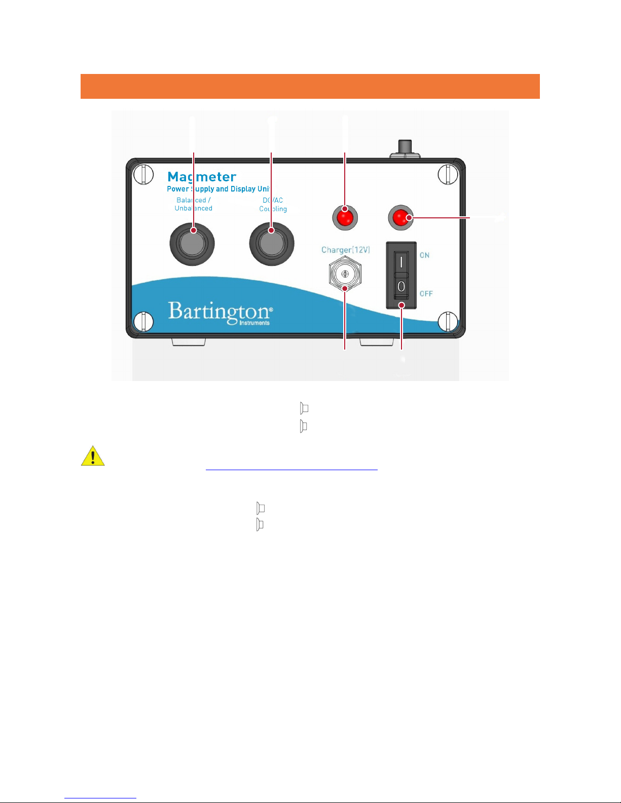
5.2. Front Panel Controls
6. Magnetometer Output Type Selector Switch
Balanced (button out)
Unbalanced (button pressed in)
Caution: This switch must be set to match your magnetometer output type to ensure
correct results (see Magnetometer Output Type Selection).
7. DC/AC Coupling (High Pass Filter (HPF) Control)
DC (button out)
AC (button pressed in)
8. Charge LED
9. On/Off LED
10. On/Off Switch
11. Socket for external charging adaptor
6 7 8
9
11 10

BARTINGTON INSTRUMENTS
Page 9 of 20 OM2448/4
5.3. Top Panel Displays
12. X Signal Value Display
13. Y Signal Value Display
14. Z Signal Value Display
Note: The displays output the RMS value of the analogue output voltages if in AC mode. If
the device is in DC mode, output is given in DC voltage.
15. Scaling Selection Switch
Caution: This switch must be set to the scaling corresponding to your magnetometer
output type to ensure correct results (see Magnetometer Output Type Selection).
Note: Where applicable, scaling parameters are indicated by 1V on Magmeter-2, e.g. the
first switch position on Magmeter-2 is 100µT/1V.
16. Backlight
Note: The button must be pressed and held to enable screen illumination.
15
12
13
14
16
BARTINGTON INSTRUMENTS
Page 10 of 20 OM2448/4
Caution: Prolonged use of the backlight will increase rate of battery discharge.
6. Installing Magmeter-2
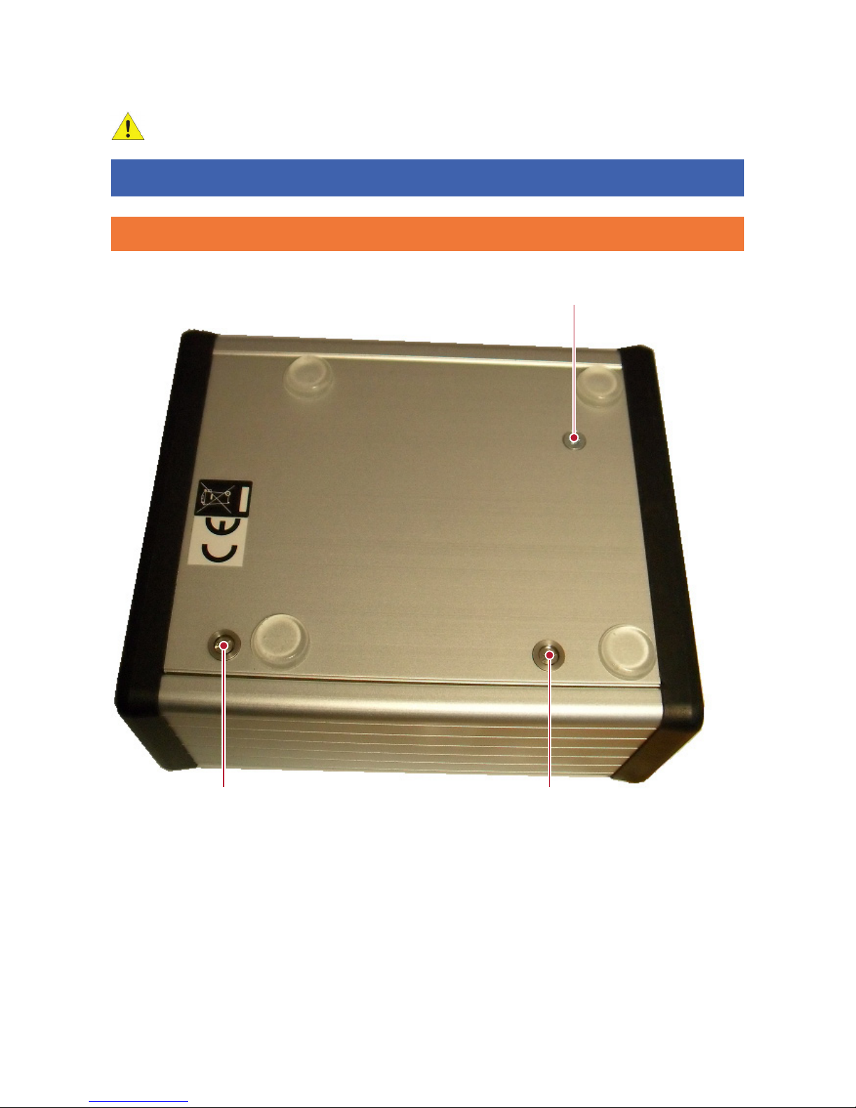
6.1. Installing and Replacing the Internal Batteries
To install the battery cells, or to remove discharged or defective cells, use the following
procedure:
Key: A – Enclosure lid retaining screw B – Enclosure lid retaining screw
C – Earth lead fixing (do not remove)
A B
C

BARTINGTON INSTRUMENTS
Page 11 of 20 OM2448/4
Place the Magmeter-2 on a suitable surface with the underside facing up and the two
enclosure lid retaining screws nearest to you.
Using a flat-bladed screwdriver of the appropriate size, fully loosen screw A to allow the edge
of the lid to clear the enclosure end cap.
Fully loosen screw B and the lid of the enclosure will lift due to the internal springs.

BARTINGTON INSTRUMENTS
Page 12 of 20 OM2448/4
Lift the lid and place aside to gain access to the battery cell compartment.
Insert each cell into the compartment in turn.

BARTINGTON INSTRUMENTS
Page 13 of 20 OM2448/4
When all 5 cells are in place, locate the back edge of the lid in the enclosure.
Tighten screws A and B in any order.
6.2. Initial Charging of the Battery Cells
To charge the Magmeter-2 batteries, connect the mains charger and switch on the mains supply
(if appropriate). The charging LED (item 8, Front Panel Controls) will begin to flash indicating
that “fast charging” is taking place. Once the fast charge cycle has completed, the LED will stop
flashing and be lit (ON) continuously, to indicate that “trickle charging” is continuing.
Note: When battery cells are inserted for the first time, they should be continuously
charged for 16 hours to ensure full capacity.
Note: The Magmeter-2 can be used whilst charging the battery cells or used directly from
mains power without any battery cells being installed. However, the outputs may carry
some charger noise.
Note: If the Magmeter-2 is powered by the mains charger with no battery cells installed,
the charging LED may flash. This is normal and can be ignored.
Note: To prepare for long periods away from a charging source, battery cells may be pre-
charged and used to replace discharged cells in the field.
Note: Battery capacity will decrease over time, depending on age and use.
6.3. Location of the Equipment
6.3.1. Potentially Hazardous Locations
A B

BARTINGTON INSTRUMENTS
Page 14 of 20 OM2448/4
WARNING: The charger supplied with this equipment is powered by mains electricity.
Do not use in wet or damp locations, where water may enter the unit and create a safety
hazard.
See also Environmental Precautions.
6.3.2. Orientation
The Magmeter-2 can be orientated horizontally or vertically.
6.3.3. Temperature
To minimise temperature induced drift effects, position the Magmeter-2:
• in a constant ambient temperature
• out of direct sunlight.
6.3.4. Proximity to Other Equipment
The Magmeter-2 contains no high frequency electronics likely to cause emissions which could
create interference with other equipment. The unit is unlikely to be affected by interference from
other equipment in the normal operating environment.
Note: The Magmeter-2 is built with ferromagnetic materials and should therefore be kept
at least 1 metre away from any magnetometers.
Caution: The Magmeter-2 should not be located in an environment with high radio
frequency noise as this would interfere with BNC connection to a DVM or Acquisition unit.
6.4. Connecting the Equipment
Caution: Do not connect or break the connection between the magnetometer and the
Magmeter-2 with the Magmeter-2 switched on, as this could cause damage to the
magnetometer.
Connect the equipment in the following sequence:
1. Ensure the ON/OFF switch (item 10 above) is OFF (position “0”).
2. Connect the magnetometer to the Magmeter-2 magnetometer socket. Ensure the connector
pins are correctly aligned with those in the socket. The locking ring should be hand-tightened
only.
3. Connect BNC outputs to your external equipment, as required.

BARTINGTON INSTRUMENTS
Page 15 of 20 OM2448/4
6.5. Initial Settings
6.5.1. Magnetometer Output Type Selection
Before switching on the equipment, set the magnetometer output type selector switch to the
correct position for your magnetometer. Refer to the appropriate magnetometer datasheets.
7. Using Magmeter-2
7.1. Environmental Precautions
Refer to product brochure DS2520 or maximum environmental, electrical and mechanical ratings
for the Magmeter.
Caution: Exceeding the maximum environmental ratings may cause irreparable damage to
the equipment.
7.2. Switching On and Off
Caution: Connect the magnetometer before switching on the Magmeter, as connecting a
“live” cable to the magnetometer may cause damage. Similarly, switch off the Magmeter-2
before disconnecting the magnetometer. See Connecting the Equipment.
With the Power switch (item 10 above) ON (position “1”), the power LED (item 9) will be
continuously lit (ON).
Note: For best results, after switching on the power, leave the Magmeter-2 for 20 minutes
for the internal temperature to stabilise, before performing any measurements.

BARTINGTON INSTRUMENTS
Page 16 of 20 OM2448/4
8. Troubleshooting
The Magmeter-2 is unlikely to suffer any defects in normal use: no internal components are
serviceable. The most likely causes of failure, and their solutions, are detailed in the following
table.
In the event of any apparent malfunction beyond those described in the table below, please email
[email protected]om, or telephone the Bartington Instruments service team on +44 (0)1993
706565.
Fault Possible Cause Soluon
No power output from
the Magmeter-2 (when
no mains connected
via the plug-in charger
adaptor)
Baery at Recharge
Baery expired Replace baeries and charge
Baery not ed Fit baeries and charge
None of the above Contact Barngton service team regarding
repair
Magmeter-2 does not
charge when mains
connected via the plug-
in charger adaptor
Baery not ed Fit baeries and charge
Failed 12V charger Replace charger
None of the above Contact Barngton service team regarding
repair
Magmeter-2 makes
buzzing sound
Baery voltage is below
5V
Recharge
Buzzer sounds when
baeries have been
removed
Faulty 12V Charger Test charger output is 12V. Replace charger.
Defecve Component Return to Barngton Instruments for repair
Magmeter-2 does
not hold its charge
(reduced baery
operaon)
Baeries expired Replace baeries and charge
Magmeter-2 stuck in AC
or DC coupling mode
Defecve component Contact Barngton service team regarding
repair

BARTINGTON INSTRUMENTS
Page 17 of 20 OM2448/4
Magmeter-2 stuck
in Balanced or
Unbalanced mode
Defecve component Contact Barngton service team regarding
repair
One or both LEDs do
not light correctly
Defecve component Contact Barngton service team regarding
repair
Backlight does not
illuminate the screen
Buon not pressed and
held
Press and hold buon to maintain backlight
Magmeter-2 defecve Contact Barngton service team regarding
repair
With a sensor
connected, all output
signals are faulty
Coupled incorrectly Check posion of AC/DC coupling switch
Balance mode set
incorrectly
Check posion of balanced/unbalanced
mode switch
Defecve sensor cable Check sensor cable using relevant datasheet.
If found to be defecve, contact Barngton
service team regarding repair
Sensor defecve Contact Barngton service team regarding
repair
Magmeter-2 defecve Contact Barngton service team regarding
repair
With a sensor
connected, one or
two output signals are
faulty
Defecve sensor cable Check sensor cable using relevant datasheet.
If found to be defecve, contact Barngton
service team regarding repair
Sensor defecve Contact Barngton service team regarding
repair
Magmeter-2 defecve Contact Barngton service team regarding
repair
No output displayed
(when not mains
connected via the plug-
in charger adaptor)
Baeries at Recharge the baeries
Baeries expired Replace baeries and charge
Baeries not ed Fit baeries and charge
None of the above Contact Barngton service team regarding
repair
BARTINGTON INSTRUMENTS
Page 18 of 20 OM2448/4
9. Care and Maintenance
The Magmeter-2 requires no routine maintenance. Apart from the battery there are no user
serviceable parts.
9.1. Fuses
As a safety feature the Magmeter-2 is fitted with a thermal fuse. If the Magmeter-2 overheats,
which could occur as a result of the fitting of incorrect battery cells, the charging circuit will
be permanently isolated. In this instance, the Magmeter-2 must be returned to Bartington
Instruments for checks and repair.
WARNING: No attempt should be made by the user to repair the unit. Repairs by
unauthorised personnel may be dangerous and could affect the safety of users, damage
the equipment and also invalidate the terms and conditions of the Warranty.
9.2. Calibration
Routine recalibration is recommended at two years interval. Please contact Bartington
Instruments service@bartington.com for enquiries.
9.3. Cleaning
Caution: Disconnect the electrical supply before performing any cleaning operation.
Periodic cleaning is not normally required.
If the system becomes soiled and cleaning is necessary:
• Use a damp cloth to clean the outer surfaces.
• Use an air duster to blow debris from the connectors.
Caution: Ensure water does not enter the system. The system must be completely dry
before the electrical supply is reconnected.
Caution: Never use chemicals, such as solvents, when cleaning the Magmeter.
Caution: Take particular care when cleaning around electrical connections. Bent or
damaged pins may cause the magnetometer to malfunction.

BARTINGTON INSTRUMENTS
Page 19 of 20 OM2448/4
10. End of Life Disposal
This product should not be disposed of in domestic or municipal waste. For information about
disposing of this product safely, check local regulations for disposal of electrical / electronic
products.
10.1. Waste Electrical and Electronic Equipment (WEEE) Regulations
This product complies fully with Restriction of the Use of Certain Hazardous Substances in
Electrical and Electronic Equipment (RoHS) and WEEE Regulations current at the time of
writing.

OM2448/4
The copyright of this document is the property of Bartington Instruments Ltd.
Bartington® is a registered trade mark of Bartington Instruments Limited in the following countries:
United Kingdom, Australia, Brazil, Canada, China, European Union, India, Japan, Norway and the
United States of America.
Bartington Instruments Limited
5 Thorney Leys Business Park,
Witney, Oxford, OX28 4GE, England.
www.bartington.com
T: +44 (0)1993 706565
F: +44 (0)1993 774813
E: sales@bartington.com
Table of contents
Other Bartington Power Supply manuals


Popular Power Supply manuals by other brands


Matsusada
Matsusada R4G Series instruction manual

Balluff
Balluff BAE PS-XA-1W-24-150-608-I installation guide

Banner
Banner FlexPower DX81P6 Specification sheet

Middle Atlantic Products
Middle Atlantic Products PDC Series Operation instructions

HP
HP 6269B OPERATOR’S, ORGANIZATIONAL, DIRECT SUPPORT AND GENERAL SUPPORT MAINTENANCE MANUA L

EPS Stromversorgung
EPS Stromversorgung PS 5040-10 A operating guide