EPS Stromversorgung PS 5040-10 A User manual

EPS
Stromversorgung
Doc ID: PS5EN
Revision: 05
Date: 01/2017
Operating Guide
PS 5000 A
DC Laboratory Power Supply


Page 3
EPS Stromversorgung GmbH
Alter Postweg 101 • 86159 Augsburg
Germany
Fon: +49 821 / 570451-0
Fax: +49 821 / 570451-25
www.eps-germany.de
info@eps-germany.de
PS 5000 A Series
TABLE OF CONTENTS
1GENERAL
1.1 About this document......................................4
1.1.1 Retention and use..........................................4
1.1.2 Copyright........................................................4
1.1.3 Validity ............................................................4
1.1.4 Symbols and warnings ..................................4
1.2 Warranty.........................................................4
1.3 Limitation of liability ........................................4
1.4 Disposal of equipment ...................................5
1.5 Product key ....................................................5
1.6 Intended usage ..............................................5
1.7 Safety .............................................................6
1.7.1 Safety notices.................................................6
1.7.2 Responsibility of the user...............................6
1.7.3 Responsibility of the operator .......................7
1.7.4 User requirements .........................................7
1.7.5 Alarm signals..................................................8
1.8 Technical Data ...............................................8
1.8.1 Approved operating conditions......................8
1.8.2 General technical data...................................8
1.8.3 Specictechnicaldata...................................9
1.8.4 Views............................................................15
1.9 Construction and function............................18
1.9.1 General description......................................18
1.9.2 Scope of delivery .........................................18
1.9.3 Accessories..................................................18
1.9.4 The control panel (HMI)...............................19
1.9.5 USB port (rear side).....................................20
1.9.6 Sense connector (remote sensing) .............20
2INSTALLATION & COMMISSIONING
2.1 Storage.........................................................21
2.1.1 Packaging ....................................................21
2.1.2 Storage.........................................................21
2.2 Unpacking and visual check........................21
2.3 Installation ....................................................21
2.3.1 Preparation...................................................21
2.3.2 Installing the device .....................................21
2.3.3 Connection to AC supply .............................22
2.3.4 Connection to DC loads...............................22
2.3.5 Grounding of the DC output ........................23
2.3.6 Connection of remote sensing ....................23
2.3.7 Connecting the USB port (rear side)...........24
2.3.8 Initial commission.........................................25
2.3.9 Commissionafterarmwareupdateora
long period of non-use.................................25
3OPERATION AND APPLICATION
3.1 Personal safety ............................................26
3.2 Operating modes .........................................26
3.2.1 Voltage regulation / Constant voltage .........26
3.2.2 Current regulation / constant current / current
limiting ..........................................................26
3.2.3 Power regulation / constant power / power
limiting ..........................................................26
3.3 Alarm conditions ..........................................27
3.3.1 Power Fail (only with 640 W models)..........27
3.3.2 Overtemperature..........................................27
3.3.3 Overvoltage protection.................................27
3.3.4 Overcurrent protection.................................27
3.3.5 Overpower protection ..................................27
3.3.6 Remote sensing...........................................27
3.4 Manual operation .........................................28
3.4.1 Switching the device on...............................28
3.4.2 Switching the device off...............................28
3.4.3 Manual adjustment of set values.................28
3.4.4 Manuallycongureprotections ...................29
3.4.5 Switching the DC output on or off................29
3.4.6 Recall feature ...............................................30
3.4.7 Control panel (HMI) lock..............................30
3.5 Remote control.............................................31
3.5.1 General.........................................................31
3.5.2 Control locations ..........................................31
3.5.3 Remote control via the digital interface.......31
3.6 Alarms and supervision ...............................32
3.6.1 Denitionofterms........................................32
3.6.2 Device alarm handling .................................32
3.7 Other applications........................................33
3.7.1 Parallel operation .........................................33
3.7.2 Series connection ........................................33
3.7.3 Operation as battery charger.......................33
4SERVICE AND MAINTENANCE
4.1 Maintenance / cleaning................................34
4.2 Faultnding/diagnosis/repair...................34
4.2.1 Replacing a defect mains fuse ....................34
4.3 Firmware updates ........................................34
5CONTACT AND SUPPORT
5.1 Repairs .........................................................34
5.2 Contact options ............................................34
Page 4
EPS Stromversorgung GmbH
Alter Postweg 101 • 86159 Augsburg
Germany
Fon: +49 821 / 570451-0
Fax: +49 821 / 570451-25
www.eps-germany.de
info@eps-germany.de
PS 5000 A Series
1. General
1.1 About this document
1.1.1 Retention and use
This document is to be kept in the vicinity of the equipment for future reference and explanation of the operation of
the device. This document is to be delivered and kept with the equipment in case of change of location and/or user.
1.1.2 Copyright
Reprinting, copying, also partially, usage for other purposes as foreseen of this manual are forbidden and breach
may lead to legal process.
1.1.3 Validity
This manual is valid for the following equipment:
Model Article no. Model Article no. Model Article no.
PS 5040-10 A 05100300 PS 5040-20 A 05100303 PS 5040-40 A 05100306
PS 5080-05 A 05100301 PS 5080-10 A 05100304 PS 5080-20 A 05100307
PS 5200-02A 05100302 PS 5200-04 A 05100305 PS 5200-10 A 05100308
1.1.4 Symbols and warnings
Warning and safety notices as well as general notices in this document are shown in a box with a symbol as follows:
Symbol for a life threatening danger
Symbol for general safety notices (instructions and damage protection bans) or important infor-
mation for operation
Symbol for general notices
1.2 Warranty
The manufacturer guarantees the functional competence of the applied technology and the stated performance
parameters. The warranty period begins with the delivery of free from defects equipment.
Terms of guarantee are included in the general terms and conditions (TOS) of EPS Stromversorgung GmbH.
1.3 Limitation of liability
All statements and instructions in this manual are based on current norms and regulations, up-to-date technology
and our long term knowledge and experience. The manufacturer accepts no liability for losses due to:
• Usage for purposes other than designed
• Use by untrained personnel
• Rebuilding by the customer
• Technical changes
• Use of not authorized spare parts
The actual delivered device(s) may differ from the explanations and diagrams given here due to latest technical
changes or due to customized models with the inclusion of additionally ordered options.

Page 5
EPS Stromversorgung GmbH
Alter Postweg 101 • 86159 Augsburg
Germany
Fon: +49 821 / 570451-0
Fax: +49 821 / 570451-25
www.eps-germany.de
info@eps-germany.de
PS 5000 A Series
1.4 Disposal of equipment
A piece of equipment which is intended for disposal must, according to European laws and regulations (ElektroG,
WEEE) be returned to the manufacturer for scrapping, unless the person operating the piece of equipment or an-
other, delegated person is conducting the disposal. Our equipment falls under these regulations and is accordingly
marked with the following symbol:
1.5 Product key
Decoding of the product description on the label, using an example:
PS 5 080 - 10 A
Generation: A= 1st generation
Maximum current of the device in Ampere
Maximum voltage of the device in Volt
Series : 5= Series 5000
Typeidentication:
PS = Power Supply, usually programmable
PSI = Power Supply Intelligent, always programmable
ELR = Electronic Load with Recovery
1.6 Intended usage
The equipment is intended to be used, if a power supply or battery charger, only as a variable voltage and current
source, or, if an electronic load, only as a variable current sink.
Typical application for a power supply is DC supply to any relevant user, for a battery charger the charging of vari-
ous battery types and for electronic loads the replacement of an ohmic resistor by an adjustable DC current sink
in order to load relevant voltage and current sources of any type.
• Claims of any sort due to damage caused by non-intended usage will not be accepted.
• All damage caused by non-intended usage is solely the responsibility of the operator.

Page 6
EPS Stromversorgung GmbH
Alter Postweg 101 • 86159 Augsburg
Germany
Fon: +49 821 / 570451-0
Fax: +49 821 / 570451-25
www.eps-germany.de
info@eps-germany.de
PS 5000 A Series
1.7 Safety
1.7.1 Safety notices
Mortal danger - Hazardous voltage
• Electrical equipment operation means that some parts can be under dangerous voltage.
Therefore all parts under voltage must be covered! This basically applies to all models,
though 40 V models according to SELV can not generate hazardous DC voltage.
• All work on connections must be carried out under zero voltage (output not connected
to load) and may only be performed by qualied and informed persons. Improper actions
can cause fatal injury as well as serious material damage.
• Never touch cables or connectors directly after unplugging from mains supply as the
danger of electric shock remains.
• Never touch the contacts on DC output terminal directly after switching off the DC out-
put, because there can still be dangerous voltage present, sinking more or less slowly
depending on the load! There also can be dangerous potential between negative DC
output to PE or positive DC output to PE due to charged X capacitors.
• The equipment must only be used as intended
• The equipment is only approved for use within the connection limits stated on the product label.
• Do not insert any object, particularly metallic, through the ventilator slots
• Avoid any use of liquids near the equipment. Protect the device from wet, damp and conden-
sation.
• For power supplies and battery chargers: do not connect users, particularly low resistance, to
devices under power; sparking may occur which can cause burns as well as damage to the
equipment and to the user.
• For electronic loads: do not connect power sources to equipment under power, sparking may
occur which can cause burns as well as damage to the equipment and to the source.
• ESD regulations must be applied when plugging interface cards or modules into the relative slot
• Interface cards or modules may only be attached or removed after the device is switched off.
It is not necessary to open the device.
• Do not connect external power sources with reversed polarity to DC input or outputs! The
equipment will be damaged.
• For power supply devices: avoid where possible connecting external power sources to the DC
output, and never those that can generate a higher voltage than the nominal voltage of the device.
• For electronic loads: do not connect a power source to the DC input which can generate a volt-
age more than 120% of the nominal input voltage of the load. The equipment is not protected
against over voltage and may be irreparably damaged.
• Alwayscongurethevariousprotectingfeaturesagainstovercurrent,overvoltageetc.forsensi-
tive loads to what the target application requires!
1.7.2 Responsibility of the user
The equipment is intended for industrial operation. Therefore the operators are governed by the legal safety
regulations. Alongside the warning and safety notices in this manual the relevant safety, accident prevention and
environmental regulations must also be applied. In particular the users of the equipment:
• must be informed of the relevant job safety requirements
• mustworktothedenedresponsibilitiesforoperation,maintenanceandcleaningoftheequipment
• before starting work must have read and understood the operating manual
• must use the designated and recommended safety equipment.

Page 7
EPS Stromversorgung GmbH
Alter Postweg 101 • 86159 Augsburg
Germany
Fon: +49 821 / 570451-0
Fax: +49 821 / 570451-25
www.eps-germany.de
info@eps-germany.de
PS 5000 A Series
1.7.3 Responsibility of the operator
Operator is any natural or legal person who uses the equipment or delegates the usage to a third party, and is
responsible during its usage for the safety of the user, other personnel or third parties.
The equipment is intended for industrial operation. Therefore the operators are governed by the legal safety
regulations. Alongside the warning and safety notices in this manual the relevant safety, accident prevention and
environmental regulations must also be applied. In particular the operator has to
• be acquainted with the relevant job safety requirements
• identifyotherpossibledangersarisingfromthespecicusageconditionsattheworkstationviaariskassessment
• introduce the necessary steps in the operating procedures for the local conditions
• regularly control that the operating procedures are current
• updatetheoperatingprocedureswherenecessarytoreectchangesinregulation,standardsoroperatingcon-
ditions.
• deneclearlyandunambiguouslytheresponsibilitiesforoperation,maintenanceandcleaningoftheequipment.
• ensure that all employees who use the equipment have read and understood the manual. Furthermore the users
are to be regularly schooled in working with the equipment and the possible dangers.
• provide all personnel who work with the equipment with the designated and recommended safety equipment
Furthermore,theoperatorisresponsibleforensuringthatthedeviceisatalltimestechnicallytforuse.
1.7.4 User requirements
Any activity with equipment of this type may only be performed by persons who are able to work correctly and
reliably and satisfy the requirements of the job.
• Personswhosereactioncapabilityisnegativelyinuencedbye.g.drugs,alcoholormedicationmaynotoperate
the equipment.
• Age or job related regulations valid at the operating site must always be applied.
Danger of injury!
Improper operation of the device can cause person or object damage. Only persons who have the
necessary training, knowledge and experience may use the equipment.
Delegated persons are those who have been properly and demonstrably instructed in their tasks and the atten-
dant dangers.
Qualied persons are those who are able through training, knowledge and experience as well as knowledge of
thespecicdetailstocarryoutalltherequiredtasks,identifydangersandavoidpersonalandotherrisks.

Page 8
EPS Stromversorgung GmbH
Alter Postweg 101 • 86159 Augsburg
Germany
Fon: +49 821 / 570451-0
Fax: +49 821 / 570451-25
www.eps-germany.de
info@eps-germany.de
PS 5000 A Series
1.7.5 Alarm signals
The equipment the possibility to signal alarm conditions, however, not danger situations. The signals are optical,
on the display as text). All alarms will cause the device to permanently or temporarily switch off the DC output.
The meaning of the signals is as follows:
Signal OT
(OverTemperature)
• Overheating of the device
• DC output will be switched off temporarily
• Non-critical
Signal OVP
(OverVoltage)
• Overvoltage shutdown of the DC output due to high voltage entering the device or gener-
ated by the device itself due to a defect
• Critical! The device and/or the load could be damaged
Signal OCP
(OverCurrent)
• Shutdown of the DC output due to excess of the preset limit
• Non-critical, protects the load from excessive current consumption
Signal OPP
(OverPower)
• Shutdown of the DC output due to excess of the preset limit
• Non-critical, protects the load from excessive power consumption
Signal PF
(Power Fail)
• DC output shutdown due to AC undervoltage or defect of the AC input circuit
• Critical on overvoltage! AC input circuit could be damaged
1.8 Technical Data
1.8.1 Approved operating conditions
• Use only inside dry buildings
• Ambient temperature 0-50°C
• Operational altitude: max. 2000 m above sea level
• Max 80% RH up to 30°C, linear decrease to 50% RH at 50°C
1.8.2 General technical data
Display: 7 segment type, 9 digits (upper row), 2x 4 digits (middle row), status symbols
Controls: 2 rotary knobs with button function, 5 pushbuttons
The nominal values for the device determine the maximum adjustable ranges.

Page 9
EPS Stromversorgung GmbH
Alter Postweg 101 • 86159 Augsburg
Germany
Fon: +49 821 / 570451-0
Fax: +49 821 / 570451-25
www.eps-germany.de
info@eps-germany.de
PS 5000 A Series
1.8.3 Specic technical data
160 W
Model
PS 5040-10 A PS 5080-05 A PS 5200-02 A
AC Input
Input voltage 90...264 V AC 90...264 V AC 90...264 V AC
Input connection 1ph,N,PE 1ph,N,PE 1ph,N,PE
Input frequency 50/60 Hz 50/60 Hz 50/60 Hz
Input fuse (internal) MT 4 A MT 4 A MT 4 A
Leak current < 3.5 mA < 3.5 mA < 3.5 mA
Power factor ~ 0.99 ~ 0.99 ~ 0.99
DC Output
Max. output voltage UMax 40 V 80 V 200 V
Max. output current IMax 10 A 5 A 2 A
Max. output power PMax 160 W 160 W 160 W
Overvoltage protection range 0...44 V 0...88 V 0...220 V
Overcurrent protection range 0...11 A 0...5.5 A 0...2.2 A
Overpower protection range 0…176 W 0…176 W 0…176 W
TemperaturecoefcientforsetvaluesΔ/K Voltage / current: 100 ppm
Voltage regulation
Adjustment range 0...40.8 V 0...81.6 V 0...204 V
Accuracy (1 (at 23 ± 5°C) < 0.1% UNom < 0.1% UNom < 0.1% UNom
Lineregulationat±10%ΔUAC < 0.02% UNom < 0.02% UNom < 0.02% UNom
Load regulation at 0...100% load < 0.05% UNom < 0.05% UNom < 0.05% UNom
Risetime10...90%ΔU Max. 30 ms Max. 30 ms Max. 30 ms
Display: Resolution See section „1.9.4.3. Resolution of the displayed values“
Display: Accuracy (4 ≤0.2%UNom ≤0.2%UNom ≤0.2%UNom
Ripple (2 < 40 mVPP
< 5 mVRMS
< 80 mVPP
< 10 mVRMS
< 150 mVPP
< 30 mVRMS
Remote sensing compensation Max. 6% UNom Max. 6% UNom Max. 6% UNom
Current regulation
Adjustment range 0...10.2 A 0...5.1 A 0...2.04 A
Accuracy (1 (at 23 ± 5°C) < 0.2% INom < 0.2% INom < 0.2% INom
Lineregulationat±10%ΔUAC < 0.05% INom < 0.05% INom < 0.05% INom
Loadregulationat0...100%ΔUOUT < 0.15% INom < 0.15% INom < 0.15% INom
Ripple (2 < 15 mARMS < 7.5 mARMS < 3 mARMS
Display: Resolution See section „1.9.4.3. Resolution of the displayed values“
Display: Accuracy (4 ≤0.2%INom ≤0.2%INom ≤0.2%INom
Compensation 10%->90% load < 1.5 ms < 1.5 ms < 1.5 ms
Power regulation
Adjustment range 0…163.2 W 0…163.2 W 0…163.2 W
Accuracy (1 (at 23 ± 5°C) < 1% PNom < 1% PNom < 1% PNom
Lineregulationat±10%ΔUAC < 0.05% PNom < 0.05% PNom < 0.05% PNom
Loadregulationat10-90%ΔUOUT*ΔIOUT < 0.75% PNom < 0.75% PNom < 0.75% PNom
Display: Resolution See section „1.9.4.3. Resolution of the displayed values“
Efciency(3 ~ 92% ~ 92% ~ 93%
(1Relatedtothenominalvalues,theaccuracydenesthemaximumdeviationbetweenanadjustedvaluesandthetrue(actual)value.
Example: a 80 V model has min. 0.1% voltage accuracy, that is 80 mV. When adjusting the voltage to 5 V, the actual value is allowed to differ max. 80 mV, which
means it might be between 4.92 V and 5.08 V.
(2 RMS value: LF 0...300 kHz, PP value: HF 0...20MHz
(3 Typical value at 100% output voltage and 100% power
(4 The display accuracy adds to the general accuracy, so the error (i.e. deviation) will be higher.

Page 10
EPS Stromversorgung GmbH
Alter Postweg 101 • 86159 Augsburg
Germany
Fon: +49 821 / 570451-0
Fax: +49 821 / 570451-25
www.eps-germany.de
info@eps-germany.de
PS 5000 A Series
160 W
Model
PS 5040-10 A PS 5080-05 A PS 5200-02 A
Insulation
Output (DC) to enclosure (PE) DC minus: permanent max. ±200 V
DC plus: permanent max. ±200V + output voltage
Input (AC) to output (DC) Max. 2500 V, short-term
Miscellaneous
Cooling Convection (typical direction: front inlet, rear exhaust)
Ambient temperature 0..50°C
Storage temperature -20...70°C
Humidity < 80%, not condensing
Standards EN 61010, EN 61326
Overvoltage category 2
Protection class 1
Pollution degree 2
Operational altitude < 2000 m
Digital interfaces
Featured 1x USB-B
Galvanic isolation from device Max. 1500 V DC
USBspecication USB 2.0, socket type B, VCOM driver
USB response time max. 2 ms
Terminals
Rear side Auxiliary DC output, AC input, remote sensing, USB-B
Front side Main DC output, ground (PE)
Dimensions
Enclosure (WxHxD) 200 x 87 x 303 mm
Total (WxHxD) 200 x 94 x min. 337 mm
Weight ~ 3 kg ~ 3 kg ~ 3 kg
Article number 05100300 05100301 05100302

Page 11
EPS Stromversorgung GmbH
Alter Postweg 101 • 86159 Augsburg
Germany
Fon: +49 821 / 570451-0
Fax: +49 821 / 570451-25
www.eps-germany.de
info@eps-germany.de
PS 5000 A Series
320 W
Model
PS 5040-20 A PS 5080-10 A PS 5200-04 A
AC Input
Input voltage 90...264 V AC 90...264 V AC 90...264 V AC
Input connection 1ph,N,PE 1ph,N,PE 1ph,N,PE
Input frequency 50/60 Hz 50/60 Hz 50/60 Hz
Input fuse (internal) MT 4 A MT 4 A MT 4 A
Leak current < 3.5 mA < 3.5 mA < 3.5 mA
Power factor ~ 0.99 ~ 0.99 ~ 0.99
DC Output
Max. output voltage UMax 40 V 80 V 200 V
Max. output current IMax 20 A 10 A 4 A
Max. output power PMax 320 W 320 W 320 W
Overvoltage protection range 0...44 V 0...88 V 0...220 V
Overcurrent protection range 0...22 A 0...11 A 0...4.4 A
Overpower protection range 0…352 W 0…352 W 0…352 W
TemperaturecoefcientforsetvaluesΔ/K Voltage / current: 100 ppm
Voltage regulation
Adjustment range 0...40.8 V 0...81.6 V 0...204 V
Accuracy (1 (at 23 ± 5°C) < 0.1% UNom < 0.1% UNom < 0.1% UNom
Lineregulationat±10%ΔUAC < 0.02% UNom < 0.02% UNom < 0.02% UNom
Load regulation at 0...100% load < 0.05% UNom < 0.05% UNom < 0.05% UNom
Risetime10...90%ΔU Max. 30 ms Max. 30 ms Max. 30 ms
Display: Resolution See section „1.9.4.3. Resolution of the displayed values“
Display: Accuracy (4 ≤0.2%UNom ≤0.2%UNom ≤0.2%UNom
Ripple (2 < 40 mVPP
< 5 mVRMS
< 80 mVPP
< 10 mVRMS
< 150 mVPP
< 30 mVRMS
Remote sensing compensation Max. 6% UNom Max. 6% UNom Max. 6% UNom
Current regulation
Adjustment range 0...20.4 A 0...10.2 A 0...4.08 A
Accuracy (1 (at 23 ± 5°C) < 0.2% INom < 0.2% INom < 0.2% INom
Lineregulationat±10%ΔUAC < 0.05% INom < 0.05% INom < 0.05% INom
Loadregulationat0...100%ΔUOUT < 0.15% INom < 0.15% INom < 0.15% INom
Ripple (2 < 20 mARMS < 15 mARMS < 6 mARMS
Display: Resolution See section „1.9.4.3. Resolution of the displayed values“
Display: Accuracy (4 ≤0.2%INom ≤0.2%INom ≤0.2%INom
Compensation 10%->90% load < 1.5 ms < 1.5 ms < 1.5 ms
Power regulation
Adjustment range 0…320 W 0…320 W 0…320 W
Accuracy (1 (at 23 ± 5°C) < 1% PNom < 1% PNom < 1% PNom
Lineregulationat±10%ΔUAC < 0.05% PNom < 0.05% PNom < 0.05% PNom
Loadregulationat10-90%ΔUOUT*ΔIOUT < 0.75% PNom < 0.75% PNom < 0.75% PNom
Display: Resolution See section „1.9.4.3. Resolution of the displayed values“
Efciency(3 ~ 93% ~ 93% ~ 93%
(1Relatedtothenominalvalues,theaccuracydenesthemaximumdeviationbetweenanadjustedvaluesandthetrue(actual)value.
Example: a 80 V model has min. 0.1% voltage accuracy, that is 80 mV. When adjusting the voltage to 5 V, the actual value is allowed to differ max. 80 mV, which
means it might be between 4.92 V and 5.08 V.
(2 RMS value: LF 0...300 kHz, PP value: HF 0...20MHz
(3 Typical value at 100% output voltage and 100% power
(4 The display accuracy adds to the general accuracy, so the error (i.e. deviation) will be higher.

Page 12
EPS Stromversorgung GmbH
Alter Postweg 101 • 86159 Augsburg
Germany
Fon: +49 821 / 570451-0
Fax: +49 821 / 570451-25
www.eps-germany.de
info@eps-germany.de
PS 5000 A Series
320 W
Model
PS 5040-20 A PS 5080-10 A PS 5200-04 A
Insulation
Output (DC) to enclosure (PE) DC minus: permanent max. ±200 V
DC plus: permanent max. ±200V + output voltage
Input (AC) to output (DC) Max. 2500 V, short-term
Miscellaneous
Cooling Temperature controlled fans, front inlet, rear exhaust
Ambient temperature 0..50°C
Storage temperature -20...70°C
Humidity < 80%, not condensing
Standards EN 61010, EN 61326
Overvoltage category 2
Protection class 1
Pollution degree 2
Operational altitude < 2000 m
Digital interfaces
Featured 1x USB-B
Galvanic isolation from device Max. 1500 V DC
USBspecication USB 2.0, socket type B, VCOM driver
USB response time max. 2 ms
Terminals
Rear side Auxiliary DC output, AC input, remote sensing, USB-B
Front side Main DC output, ground (PE)
Dimensions
Enclosure (WxHxD) 200 x 87 x 303 mm
Total (WxHxD) 200 x 94 x min. 337 mm
Weight ~ 3 kg ~ 3 kg ~ 3 kg
Article number 05100303 05100304 05100305

Page 13
EPS Stromversorgung GmbH
Alter Postweg 101 • 86159 Augsburg
Germany
Fon: +49 821 / 570451-0
Fax: +49 821 / 570451-25
www.eps-germany.de
info@eps-germany.de
PS 5000 A Series
640 W
Model
PS 5040-40 A PS 5080-20 A PS 5200-10 A
AC Input
Input voltage 90...264 V AC 90...264 V AC 90...264 V AC
- with additional derating 90...150 V AC 90...150 V AC 90...150 V AC
Input connection 1ph,N,PE 1ph,N,PE 1ph,N,PE
Input frequency 50/60 Hz 50/60 Hz 50/60 Hz
Input fuse (internal) MT 8 A MT 8 A MT 8 A
Leak current < 3.5 mA < 3.5 mA < 3.5 mA
Power factor ~ 0.99 ~ 0.99 ~ 0.99
DC Output
Max. output voltage UMax 40 V 80 V 200 V
Max. output current IMax 40 A 20 A 10 A
Max. output power PMax 640 W 640 W 640 W
Overvoltage protection range 0...44 V 0...88 V 0...220 V
Overcurrent protection range 0...44 A 0...22 A 0...11 A
Overpower protection range 0…704 W 0…704 W 0…704 W
TemperaturecoefcientforsetvaluesΔ/K Voltage / current: 100 ppm
Voltage regulation
Adjustment range 0...40.8 V 0...81.6 V 0...204 V
Accuracy (1 (at 23 ± 5°C) < 0.1% UNom < 0.1% UNom < 0.1% UNom
Lineregulationat±10%ΔUAC < 0.02% UNom < 0.02% UNom < 0.02% UNom
Load regulation at 0...100% load < 0.05% UNom < 0.05% UNom < 0.05% UNom
Risetime10...90%ΔU Max. 30 ms Max. 30 ms Max. 30 ms
Display: Resolution See section „1.9.4.3. Resolution of the displayed values“
Display: Accuracy (4 ≤0.2%UNom ≤0.2%UNom ≤0.2%UNom
Ripple (2 < 40 mVPP
< 5 mVRMS
< 80 mVPP
< 10 mVRMS
< 150 mVPP
< 30 mVRMS
Remote sensing compensation Max. 6% UNom Max. 6% UNom Max. 6% UNom
Current regulation
Adjustment range 0...40.8 A 0...20.4 A 0...10.2 A
Accuracy (1 (at 23 ± 5°C) < 0.2% INom < 0.2% INom < 0.2% INom
Lineregulationat±10%ΔUAC < 0.05% INom < 0.05% INom < 0.05% INom
Loadregulationat0...100%ΔUOUT < 0.15% INom < 0.15% INom < 0.15% INom
Ripple (2 < 60 mARMS < 30 mARMS < 12 mARMS
Display: Resolution See section „1.9.4.3. Resolution of the displayed values“
Display: Accuracy (4 ≤0.2%INom ≤0.2%INom ≤0.2%INom
Compensation 10%->90% load < 1.5 ms < 1.5 ms < 1.5 ms
Power regulation
Adjustment range 0…652.8 W 0…652.8 W 0…652.8 W
Accuracy (1 (at 23 ± 5°C) < 1% PNom < 1% PNom < 1% PNom
Lineregulationat±10%ΔUAC < 0.05% PNom < 0.05% PNom < 0.05% PNom
Loadregulationat10-90%ΔUOUT*ΔIOUT < 0.75% PNom < 0.75% PNom < 0.75% PNom
Display: Resolution See section „1.9.4.3. Resolution of the displayed values“
Efciency(3 ~ 92% ~ 92% ~ 93%
(1Relatedtothenominalvalues,theaccuracydenesthemaximumdeviationbetweenanadjustedvaluesandthetrue(actual)value.
Example: a 80 V model has min. 0.1% voltage accuracy, that is 80 mV. When adjusting the voltage to 5 V, the actual value is allowed to differ max. 80 mV, which
means it might be between 4.92 V and 5.08 V.
(2 RMS value: LF 0...300 kHz, PP value: HF 0...20MHz
(3 Typical value at 100% output voltage and 100% power
(4 The display accuracy adds to the general accuracy, so the error (i.e. deviation) will be higher.

Page 14
EPS Stromversorgung GmbH
Alter Postweg 101 • 86159 Augsburg
Germany
Fon: +49 821 / 570451-0
Fax: +49 821 / 570451-25
www.eps-germany.de
info@eps-germany.de
PS 5000 A Series
640 W
Model
PS 5040-40 A PS 5080-20 A PS 5200-10 A
Insulation
Output (DC) to enclosure (PE) DC minus: permanent max. ±200 V
DC plus: permanent max. ±200V + output voltage
Input (AC) to output (DC) Max. 2500 V, short-term
Miscellaneous
Cooling Temperature controlled fans, front inlet, rear exhaust
Ambient temperature 0..50°C
Storage temperature -20...70°C
Humidity < 80%, not condensing
Standards EN 61010, EN 61326
Overvoltage category 2
Protection class 1
Pollution degree 2
Operational altitude < 2000 m
Digital interfaces
Featured 1x USB-B
Galvanic isolation from device Max. 1500 V DC
USBspecication USB 2.0, socket type B, VCOM driver
USB response time max. 2 ms
Terminals
Rear side Auxiliary DC output, AC input, remote sensing, USB-B
Front side Main DC output, ground (PE)
Dimensions
Enclosure (WxHxD) 200 x 87 x 333 mm
Total (WxHxD) 200 x 94 x min. 367 mm
Weight ~ 4.3 kg ~ 4.3 kg ~ 4.3 kg
Article number 05100306 05100307 05100308

Page 15
EPS Stromversorgung GmbH
Alter Postweg 101 • 86159 Augsburg
Germany
Fon: +49 821 / 570451-0
Fax: +49 821 / 570451-25
www.eps-germany.de
info@eps-germany.de
PS 5000 A Series
Figure 1 - Front side
Figure 2 - Back side
1.8.4 Views
A - Mains switch
B - Control panel
C - DC output
D - Exhausts
E - Control interface (USB)
F - Exhausts
G - AC input socket with fuse

Page 17
EPS Stromversorgung GmbH
Alter Postweg 101 • 86159 Augsburg
Germany
Fon: +49 821 / 570451-0
Fax: +49 821 / 570451-25
www.eps-germany.de
info@eps-germany.de
PS 5000 A Series
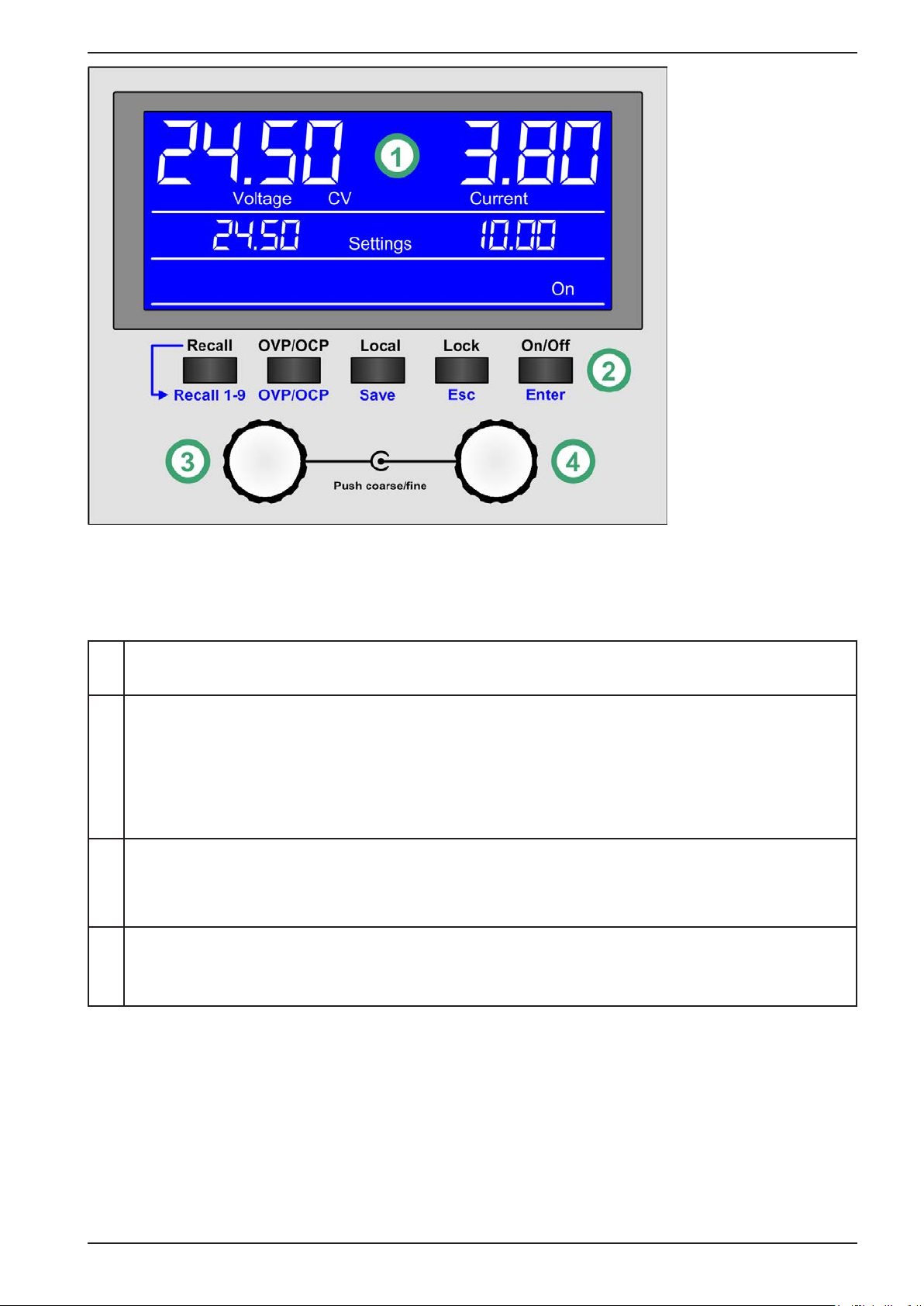
Figure 5 - Control Panel
Overview of the elements of the operating panel
For a detailed description see section „1.9.4. The control panel (HMI)“.
(1) Display
Used for indication of set values, actual values and status.
(2)
Button bank (5 buttons)
Button Recall: Recalls stored presets (see 3.4.6)
Button OVP/OCP: Switches to adjustment of OVP, OCP and OPP values
Button Local: Activation / deactivation of the remote control inhibit (see 3.5.2)
Button Lock: Activation / deactivation of the control panel lock (see 3.4.7)
Button On/Off: Switches the DC output on or off (during manual control), acknowledges alarms
(3)
Left hand rotary knob, with button function
Turn: adjusts the set value of voltage or power, as well as the values OVP and OPP
Push:togglesbetweenneandcoarsevalueadjustment
(4)
Right hand rotary knob, with button function
Turn: adjusts the set value of current, as well as the values OCP
Push:togglesbetweenneandcoarsevalueadjustment

Page 18
EPS Stromversorgung GmbH
Alter Postweg 101 • 86159 Augsburg
Germany
Fon: +49 821 / 570451-0
Fax: +49 821 / 570451-25
www.eps-germany.de
info@eps-germany.de
PS 5000 A Series
1.9 Construction and function
1.9.1 General description
The electronic DC laboratory power supplies of the PS 5000 A series are especially suitable for laboratories, work-
shops, school and other educational facilities due to their compact construction in a desktop enclosure.
For remote control using a PC or PLC the devices are provided as standard with an USB slot on the rear side. The
interface are galvanically isolated from the DC output.
Series or parallel connection are possible. The DC output clamps on the front are suitable to connect soldered
cable ends, spade lugs, cable end sleeves or 4mm Büschel plugs.
All models are controlled by microprocessors. These enable an exact and fast measurement and display of actual
values.
1.9.2 Scope of delivery
1 x Power supply device
1 x 1.5 m power cord
1xSocketadapterUK
1 x 1.8 m USB cable
1 x USB stick with software and documentation
1.9.3 Accessories
For these devices the following accessories are available:
Safety adapters
Art. no.: 10900114
Set of safety adapters (1x red, 1x black, gold covered, max. 32 A) for
later mechanical installation onto the front side DC output connectors, in
order to make them not exposed to touch. The adapters are supposed
to receive 4mm safety plugs (normal or isolated).
Page 19
EPS Stromversorgung GmbH
Alter Postweg 101 • 86159 Augsburg
Germany
Fon: +49 821 / 570451-0
Fax: +49 821 / 570451-25
www.eps-germany.de
info@eps-germany.de
PS 5000 A Series
1.9.4 The control panel (HMI)
The HMI (Human Machine Interface)consistsofadisplay,tworotaryknobswithbuttonfunctionandvepushbuttons.
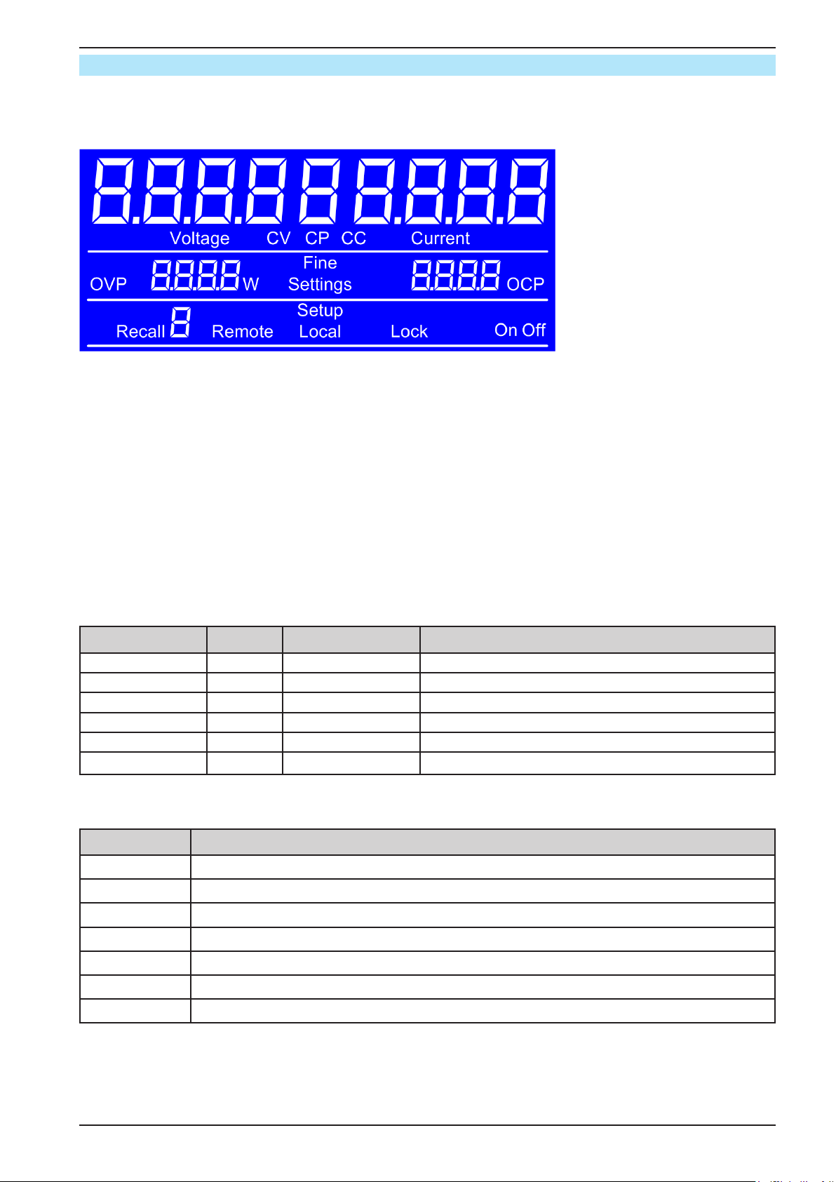
1.9.4.1 Display
The blue, illuminated LCD display is divided into a three rows:
Actual values U / I,
Errors / alarms,
Regulation mode
Set values U / I / P,
Values OVP, OCP, OPP,
Fine adjustment mode
Status, Recall feature
• Actual values area (upper row)
In normal operation the DC output values (actual values, large numbers, 7-segment) of voltage and current are
displayed with four digits each. The display format of values is according to what’s listed in 1.9.4.3. Below the actual
values, it shows the actual regulation mode (CC, CV, CP) as long as the DC output is switched on.
• Set values area (middle row)
The set values of voltage and current are displayed here, which are adjustable with the left hand and right hand
rotary knobs below the display, when operating the device manually. While doing so, the adjustment mode can be
switchedbetweenneandcoarsebypushinganyoftherotaryknobs.
The left hand rotary knob is assigned either to the output voltage and related parameter OVP or the power and the
related parameter OPP, whereas the right hand rotary knobs is always assigned to the output current and related
parameter OCP. In remote control condition, the set values given from remote are displayed here.
This row furthermore indicates alarm conditions. See „3.6. Alarms and supervision“ for details.
General display and setting ranges:
Display Unit Range Description
Actual voltage V 0-125% UNom Actual values of DC output voltage
Set value voltage V 0-102% UNom Set value for limiting the DC output voltage
Actual current A 0.1-125% INom Actual value of DC output current
Set value current A 0-102% INom Set value for limiting the DC output current
Set value power W 0-102% PNom Set value for limiting the DC output power
Protection settings none or W 0-110% Nominal val. OVP, OCP, OPP
• Status area (lower half, middle)
This row indicates various statuses:
Display Description
Recall 1-9 Number of the currently selected preset in recall mode (see 3.4.6)
Remote The device is under remote control via USB interface
Setup The device in setup menu, in this case power set value adjustment mode
Lock The control panel (HMI) is locked (see 3.4.7)
Local The device has been locked by the user explicitly against remote control
On / Off Indicates the state of the DC output
Fine Fine adjustment mode currently active (temporary, not stored, default: not active)

Page 20
EPS Stromversorgung GmbH
Alter Postweg 101 • 86159 Augsburg
Germany
Fon: +49 821 / 570451-0
Fax: +49 821 / 570451-25
www.eps-germany.de
info@eps-germany.de
PS 5000 A Series
1.9.4.2 Rotary knobs
As long as the device is in manual operation, the two rotary knobs are used to adjust set values. For a detailed
description of the individual functions see section „3.4. Manual operation“. Both rotary knobs have an additional
pushbuttonfunctiontoswitchtheadjustmentmodebetweenne(displayshowFine) and coarse adjustment. Both
knobs can switch both modes. See 3.4.3 for details.
Coarsemodemeanstoalwaysincrementordecrementanyvalueby1,whilenemodeisconnectedtothelast
decimal place (see table in 1.9.4.3).
1.9.4.3 Resolution of the displayed values
All adjustable values have 4 digits. The number of decimal places depends on the device model. Actual and set
values related to the same physical unit always have the same number of digits.
Adjustment resolution and number of digits of set values in the display:
Voltage, OVP Current, OCP Power, OPP
Nominal
Digits
Increment Nominal
Digits
Increment Nominal
Digits
Increment
40 V / 80 V 4 0.01 V 2 A / 4 A / 5 A 40.001 A 160 W 4 0.1 W
200 V 4 0.1 V 10 A / 20 A 40.01 A 320 W 4 0.1 W
40 A 40.01 A 640 W 4 0.1 W
In manual operation every set value can be set in the increments given above. In this case
the actual output values set by the device will lie within percentage tolerances as shown in the
technical data sheets. These will inuence the actual values.
1.9.5 USB port (rear side)
TheUSBportonthebacksideofthedeviceisprovidedforcommunicationwiththedeviceandforrmwareupdates.
The included USB cable can be used to connect the device to a PC (USB 2.0, USB 3.0). The driver is delivered
on the included USB stick or is available as download and installs a virtual COM port. Details for remote control
can be found in external documentation, a general programming guide, on the web site of the manufacturer or on
the included USB stick.
The device can be addressed via the USB port using the international standard ModBus protocol.
1.9.6 Sense connector (remote sensing)
If the output voltage has to be dependant on the consumer location rather than the DC output of
the power supply, then the input “Sense” can be connected to the consumer where the DC con-
nection is made. This compensates, up to a certain limit, the voltage difference between the power
supply output and the consumer, which is caused by the high current through the load cables.
The maximum possible compensation is given in the technical data.
This manual suits for next models
7
Table of contents
Other EPS Stromversorgung Power Supply manuals


