Datcon DT2500 Series User manual
DT2500
IS Power Supply
Operating manual

DT2500
2 20171220-V1
Contents
1. About this document..............................................................4
1.1. Function...............................................................................................4
1.2. Target group........................................................................................4
1.3. Symbolism used .................................................................................. 4
2. For your safety........................................................................5
2.1. Authorized personal.............................................................................5
2.2. Appropriate use ...................................................................................5
2.3. Warning about misuse......................................................................... 5
2.4. General safety instructions ..................................................................5
2.5. EU conformity......................................................................................5
2.6. Safety information for Ex areas............................................................5
2.7. Environmental instructions...................................................................6
3. Product description................................................................6
3.1. Delivery configuration .......................................................................... 6
3.2. Type designation .................................................................................6
3.3. Principle of operation...........................................................................7
3.4. Adjustment ..........................................................................................7
3.5. LED indicators .....................................................................................8
3.6. Storage and transport.......................................................................... 8
4. Mounting .................................................................................9
4.1. General instruction ..............................................................................9
4.2. Main dimension of the instrument ........................................................9
4.3. Mounting procedure........................................................................... 10
5. Connecting............................................................................11
5.1. Preparing the connection................................................................... 11
5.2. Connecting the load unit to the device ............................................... 12
5.3. Connecting the power supply ............................................................ 13
5.4. Put the instrument under power supply ............................................. 13
6. First step ...............................................................................14
6.1. First step............................................................................................ 14
7. Settings .................................................................................14
7.1. The general settings .......................................................................... 14

DT2500
20171220-V1 3
8. Fault rectification..................................................................15
8.1. Fault finding....................................................................................... 15
8.2. Repairing ........................................................................................... 15
9. Dismounting..........................................................................16
9.1. Dismounting procedure...................................................................... 16
9.2. Disposal............................................................................................. 16
10. Appendix.............................................................................17
10.1. Technical specification..................................................................... 17
10.2. ATEX certification ............................................................................ 19
DT2500
4 20171220-V1
start 1. About this document
1.1. Function
This operating instructions manual has all the information you need for
quick set-up and safe operation of DT2500.
Please read this manual before you start setup.
1.2. Target group
This operating instructions manual is directed to trained personnel.
The contents of this manual should be made available to these
personnel and put into practice by them.
1.3. Symbolism used
Information, tip, note
This symbol indicates helpful additional information
Caution, warning, danger
This symbol informs you of a danger situation that could occur.
Ignoring this cautionary note can impair the person and/or the
instrument.
Ex application
This symbol indicates special instruction for Ex application.
•List
The dot set in front indicates a list with no implied sequence.
→Action
This arrow indicates a single action.
1
Sequence
Numbers set in front indicate successive steps in a procedure.
DT2500
20171220-V1 5
2. For your safety
2.1. Authorized personal
All operations described in this operating instructions manual must be
carried out only by trained and authorized specialist personnel. For
safety and warranty reasons, any internal work on the instruments
must be carried out only by DATCON personnel.
2.2. Appropriate use
The DT2500 is an intrinsically safe isolator / power supply product
family. Detailed information on the application range is available in
chapter 3. Product description.
2.3. Warning about misuse
Inappropriate or incorrect use of the instrument can give rise to
application-specific hazards, or damage to system components
through incorrect mounting or adjustment.
2.4. General safety instructions
The DT2500 is a high-tech instrument requiring the strict observance
of standard regulations and guidelines.
The user must take note of the safety instructions in this operating
instructions manual, the country-specific installation standards as well
as all prevailing safety regulations and accident prevention rules.
2.5. EU conformity
The DT2500 is in conformity with the provisions of the following
standards:
MSZ EN 60079-0:2013 (ATEX)
MSZ EN 60079-0:2013/A11:2014 (ATEX)
MSZ EN 60079-11:2012 (ATEX)
MSZ EN 61326-1:2013 (EMC)
MSZ EN 55011:2016 (EMC)
MSZ EN 55011:2016/A1:2017 (EMC)
MSZ EN 61010-1:2011 (LVD)
MSZ EN 50581:2011 (RoHS 2)
2.6. Safety information for Ex areas
Please note the Ex-specific safety information for installation and
operation in Ex areas.
DT2500
6 20171220-V1
2.7. Environmental instructions
Protection of the environment is one of our most important duties.
Please take note of the instructions written in the following chapters:
•3.6. Storage and transport
• 9.2. Disposal
3. Product description
3.1. Delivery configuration
Delivered items
The scope of delivery encompasses:
•DT2500
•documentation:
this operating instructions manual
certification warranty
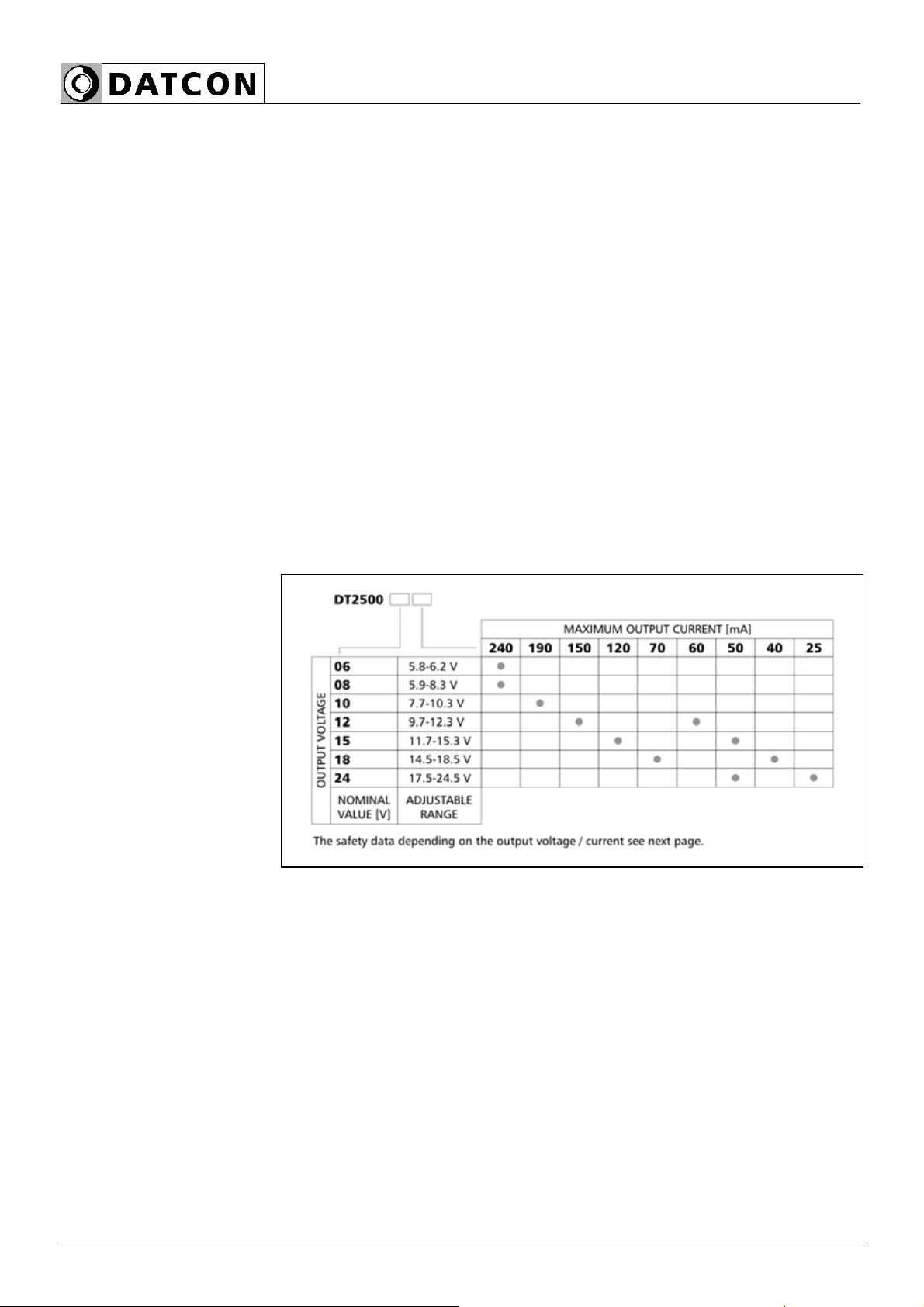
3.2. Type designation
DT2500
20171220-V1 7
3.3. Principle of operation
Area of application
The DT2500 IS Power Supply provide IS power for devices operate in
zone 1 potentially explosive area.
The power supplies are available in seven different output voltage and
current variations (see table on the previous page). A front panel
potentiometer makes possible to adjusting the output voltages,
therefore any voltage of range the 5,8 - 24 V can be ensured. The
LED indicators show information from output voltages, and the fault
conditions.
The EEx classification of the power supplies is: II (2)G [Ex ib Gb] IIC
or II (2)G [Ex ib Gb] IIB.
You can see the detailed information on chapter 10.1. Technical
specification.
Operating principle
The connected line voltage through voltage transformers, through the
rectification and filtration come to the input of control circuit. The
control circuit generates - depending of the type – the output voltage.
This voltage goes to two independent current limiting units. These
currents limits units are ensure the Io short-current. In case of
overload, the red LED light. After the currents limit units the output
voltages come in the outputs terminals. The Uo output voltage is
limited by zener diodes.
If the supply voltage higher than 250 V safety value, the mains fuse
blow out. The thermal fuse protects the power transformer from
overheating.
Power supply 200-250 VAC; 50/60 Hz
10 VA/7 W
3.4. Adjustment
After the device connected to the power supply ready for operation.
You can find detailed information for settings on 7. Settings chapter.

DT2500
8 20171220-V1
3.5. LED indicators
The following figure shows the front panel LED indicators:
1, "overload" indicator, light red, indicates the unit is overloaded.
2, "power" indicator, light green, indicates the output voltage is
present.
3, P1 potentiometer to adjust the output voltage.
3.6. Storage and transport
This instrument should be stored and transport in places whose
climatic conditions are in accordance with chapter 10.1. Technical
specification as described under the title: Ambient conditions.
The packaging of DT2500 consist of environment-friendly, recyclable
cardboard is used to protect the instrument against the impacts of
normal stresses occurring during transportation. The corragulated
cardboard box is made from environment-friendly, recyclable paper.
The inner protective material is polyfoam and nylon, which should be
disposed of via specialized recycling companies.
DT2500
20171220-V1 9
4. Mounting
4.1. General instruction
The instrument should be installing in the safe area in a cabinet with
sufficient IP protection, where the operating conditions are in
accordance with chapter 10.1. Technical specification, as described
under the title: Operating conditions.
Mounting position
The instruments are designed in housing for mounting on TS-35 rail.
The instruments should be mounted in vertical position (horizontal rail
position).
There are spacers both sides of the housing to keep 15 mm distance
between the instruments for the sufficient cooling.
Horizontal mounting may cause overheating and damage of the
instrument!
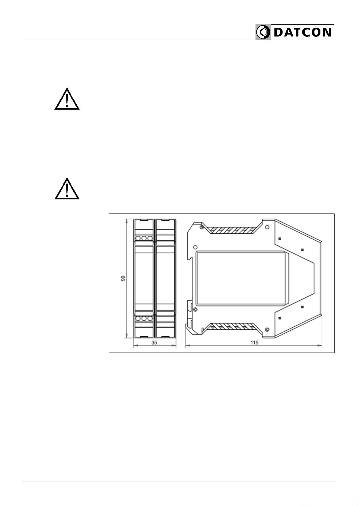
4.2. Main dimension of the instrument
DT2500
10 20171220-V1
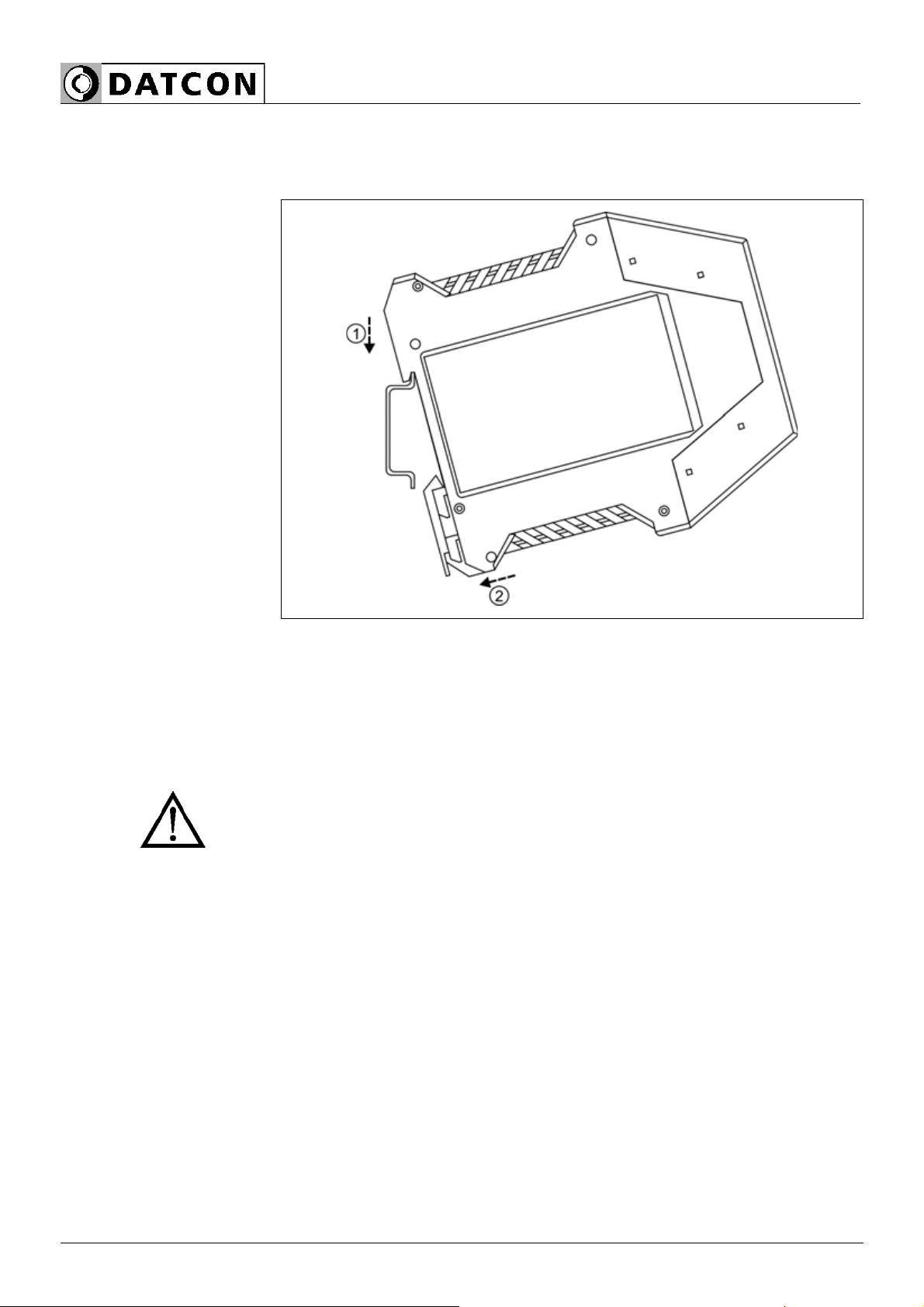
4.3. Mounting procedure
The following figure shows the mounting procedures (fixing on the
rail):
Mounting on the rail
The mounting doesn’t need any tool.
1. Tilt the instrument according to the figure; put the instrument’s
mounting hole onto the upper edge of the rail (figure step 1.).
2. Push the instrument’s bottom onto the bottom edge of the rail
(figure step 2.); you will hear the fixing assembly closing.
3. Check the hold of the fixing by moving the instrument firmly.
Leave at least 15 to 15 mm air space on both sides of the power
supply.
DT2500
20171220-V1 11
5. Connecting
5.1. Preparing the connection
Select and prepare
connection cable
Always observe the following safety instructions:
•When you are going to install instruments in hazardous area or
install instruments which are connecting to instruments are working in
hazardous area you should take note of the appropriate regulations,
conformity and type approval certificates of the DT2500 and other
instrument. The connection must be carried out by trained and
authorized personnel only!
•Connect only in the complete absence of supply voltage
•Use only a screwdriver with appropriate head
Take note the suitability of the connecting cable
(Wire cross-section, insulation, etc.).
The wire cross-section should be 0.25-1.5 mm.
You may use either solid conductor or flexible conductor.
In case of using flexible conductor use crimped wire end.
The compensating current can not flow on the cable shield!
The cable shield should only be grounded on one side, preferably on
the instrument room. Make sure that, the shield should be
continuous, between the source (DT2500) and the connected device
Take note of the corresponding installation regulations for
Ex applications. In particular, make sure that no potential equalization
currents flow over the cable screen. Ground only one side the cable
screen (it’s recommended the transmitter side).
If necessary of grounding on both sides (for suppress very high level,
high frequency interference signals) this can be achieved by use of a
blocking capacitor (e.g. ceramic capacitor 1 nF, 1500 V) or separate
potential equalization. The low frequency potential equalization
currents are thus suppressed, but the protective effect against high
frequency interference signals remains.
The DT2500 device has a very effective interference protection,
therefore grounding both sides of the cable is usually not necessary.
if interference emitting devices operating beside the DT2500 device
(eg inverter) may require the application of the above. Important rule
that the signal cables, control and power cables pass it separately.

DT2500
12 20171220-V1
5.2. Connecting the load unit to the device
The following figure shows the load unit connection to devices.
Wiring plan, connecting
the load (see also
“Application example”)
Be careful the polarity of
the cables
1. Loosen terminal screws.
2. Insert the wire ends into the open terminals according to the wiring
plan.
3. Screw the terminal in.
4. Check the hold of the wires in terminals by pulling on them firmly.
Checking the
connections
Check if the cables are connected properly (have you connected all
the cables, have you connected to the right place, do not the cable-
ends touch each other).
DT2500
20171220-V1 13
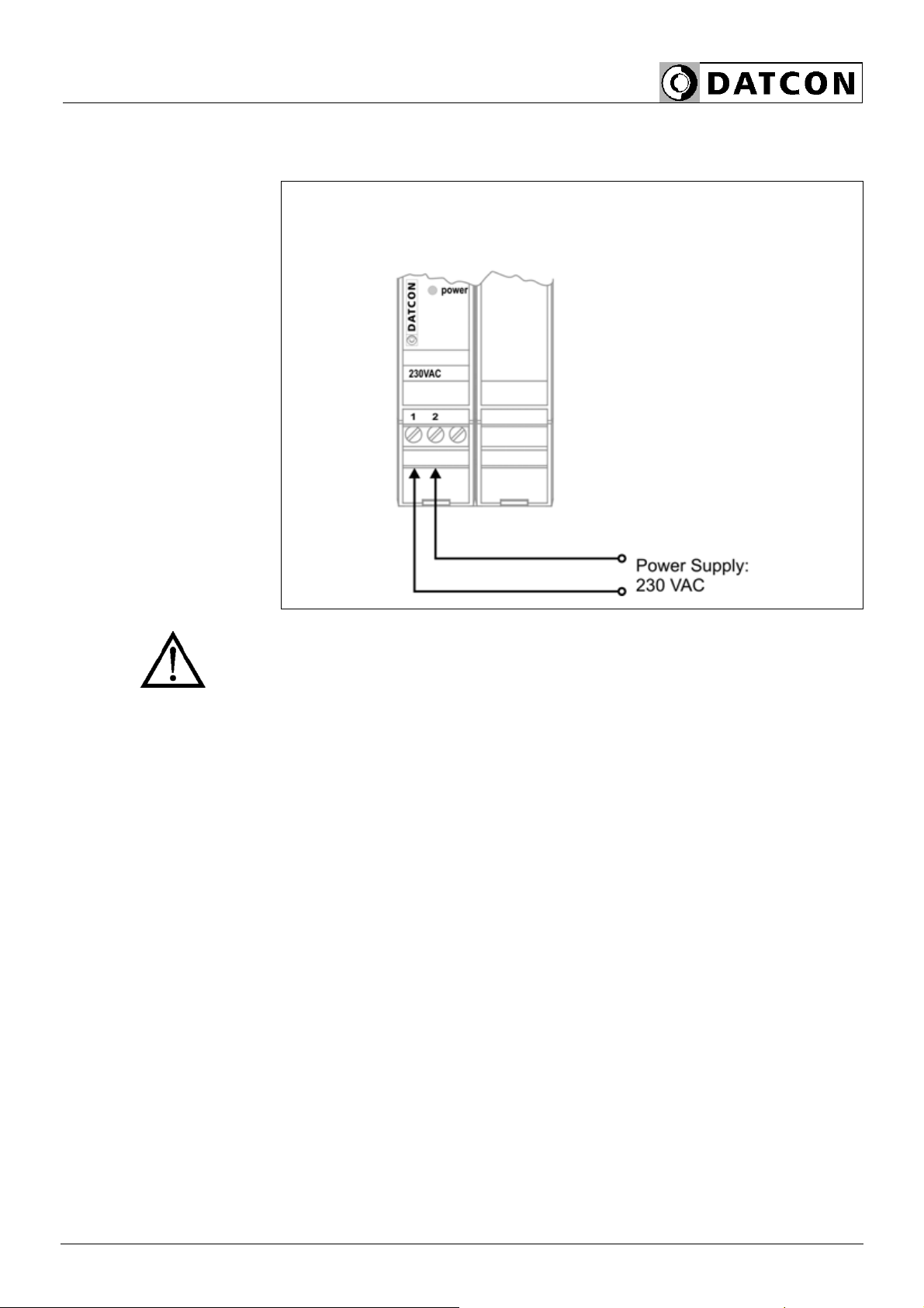
5.3. Connecting the power supply
The following figure shows the power supply connection to devices.
Wiring plan, connecting
the power supply
(see also “Application
example”)
Be careful the polarity of
the cables
The power supply should be operated only from 10 A overcurrent
protection provided power network.
1. Loosen terminal screws.
2. Insert the wire ends into the open terminals according to the wiring
plan.
3. Screw the terminal in.
4. Check the hold of the wires in terminals by pulling on them firmly.
Checking the
connections
Check if the cables are connected properly (have you connected all
the cables, have you connected to the right place, do not the cable-
ends touch each other).
5.4. Put the instrument under power supply
Put the instrument
under supply voltage
After you have completed the connections, put the instrument under
supply voltage. If the connection is correct the green indicator gives
light and you can measure on output the output voltage.

DT2500
14 20171220-V1
6. First step
6.1. First step
After turning on the power, the device ready to use.
If the factory setting is good, you do not need configurable anything.
If you want configurable your device, before the normal use you need
follow the 7. Settingschapter.
7. Settings
7.1. The general settings
Necessary devices The setup requires the following devices:
•Voltmeter, measure the output voltage
•Screwdriver, to adjust the output voltage
Setting process The output voltage is set to the nominal voltage
(6, 8, 10, 12, 15, 18 or 24 V) by manufacturer. If you want smaller
voltage as the nominal value you can adjust the voltage with
P1 potentiometer. The adjusting you should only with free output
terminals.
1. Turn off the device (Turn off the power)
2. Disconnect the load from output terminals
3. Connect the voltmeter to the outputs terminals
4. Turn on the device (Turn on the power)
5. Adjust the output voltage with P1 potentiometer. The adjusted
voltage deviation is 1 % from the load voltage value
6. Turn off the device (Turn off the power)
7. Disconnect the voltmeter from output terminals
8. Connect the load to the outputs terminals
9. Turn on the device (Turn on the power)
The inductance of the cable and capacitance of the cable shall be
deducted from the security data (Lo, Co).

DT2500
20171220-V1 15
8. Fault rectification
8.1. Fault finding
The fault finding must be carried out by trained and authorized
personnel only! Use only an Ex proofed measuring instrument when
measuring on the input (Ex) side.
•The green indicator is dark →check the power supply.
If the supply voltage is OK, the instrument is defective.
•There is no output signal →check the power supply and overload
indicator.
If the supply voltage is OK, and the overload indicator is dark, the
instrument is defective.
When the result of fault finding is that the DT2500 is defective call the
manufacturer service department.
8.2. Repairing
There is no user repairable part inside the instrument.
In accordance with Chapter 2.1.: For safety and warranty reasons,
any internal work on the instrument must be carried out by
DATCON personnel.

DT2500
16 20171220-V1
9. Dismounting
9.1. Dismounting procedure
The following figure shows the dismounting procedures:
Dismounting from the
rail
The dismounting procedure needs a screwdriver for slotted screws.
1. Before dismounting disconnect all wires.
2. Put the screwdriver end into the fixing assembly’s hole (figure step
1.).
3. Lift the screwdriver handle until it possible to open the fixing
assembly (figure step 2.).
4. Keeping the screwdriver in this position lift the instrument bottom
from the bottom edge of the rail (figure step 3.).
Lift the whole instrument (you may put out the screwdriver) (figure
step 4), the instrument will be free.
9.2. Disposal
According with the concerning EU directive, the manufacturer
undertakes the disposal of the instrument that are manufactured by it
and intended to be destroyed. Please deliver it in contamination-free
condition to the site of the Manufacturer or to a specialized recycling
company.
stop
DT2500
20171220-V1 17
10. Appendix
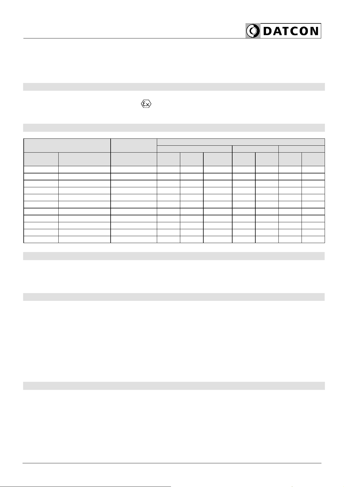
10.1. Technical specification
Intrinsical safety data:
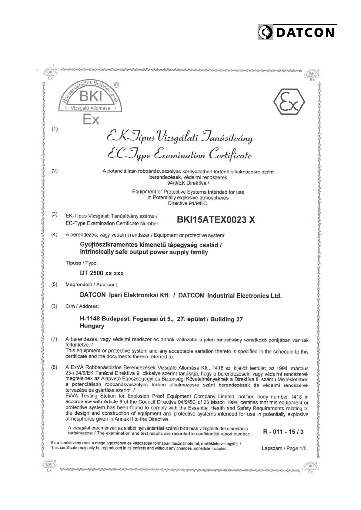
Certification: BKI 15 ATEX 0023 X, BKI 15 ATEX 0023 X/1
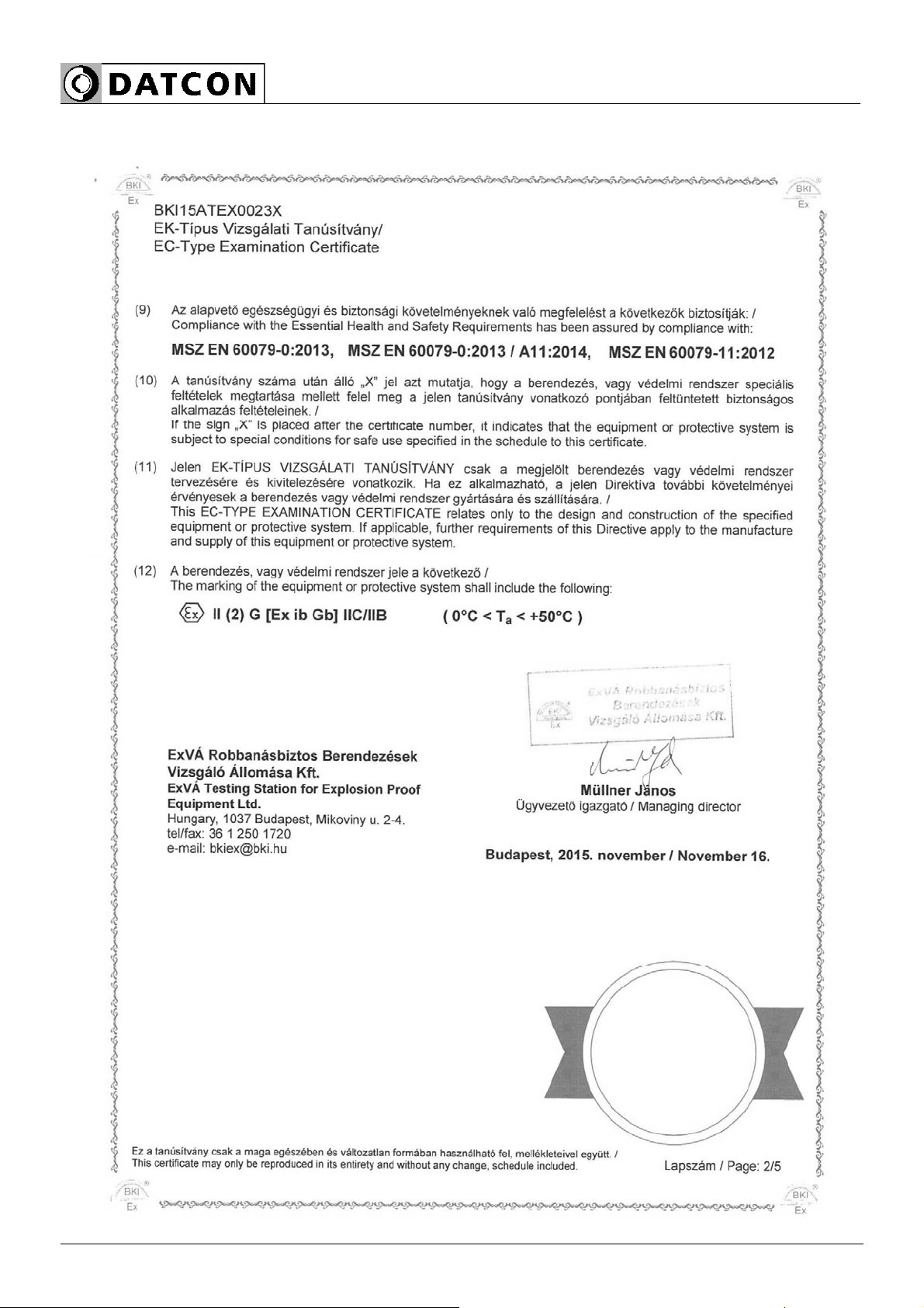
Protection marking: II (2)G [Ex ib Gb] IIC/IIB (0 °C < Ta < +50 °C)
Um: 250 Veff
Gyújtószikramentességre vonatkozó biztonsági adatok:
Safety dataOutput
voltages Output
current IIC IIB
Névleges
érték [V] Adjustment
range [V] max. [mA] Uo [V] Io [mA] Po [mW] Co [nF] Lo [mH] Co [nF] Lo [mH]
6.0 5.8-6.2 240 7.7 273 2102 300 0.15 1000 0.5
8.0 5.9-8.3 240 11.2 273 3058 250 0.15 750 0.5
10.0 7.7-10.3 190 12.4 224 2778 200 0.2 500 0.5
12.0 9.7-12.3 150 15.1 178 2688 150 0.3 400 1
12.0 9.7-12.3 60 15.1 80 1208 150 1.0 400 3
15.0 11.7-15.3 120 18.8 145 2726 100 0.34 300 1
15.0 11.7-15.3 50 18.8 70 1316 100 1.0 300 3
18.0 14.5-18.5 70 22.4 91 2038 50 1.0 150 3
18.0 14.5-18.5 40 22.4 58 1299 50 2.5 150 5
24.0 17.5-24.5 50 30.0 70 2100 30 2.0 100 5
24.0 17.5-24.5 25 30.0 42 1260 30 5.0 100 5
Safety data: MSZ EN 61010-1:2011
Pollution level: 2
Overvoltage group: II
Over current protection in installation: 6 A
Outputs parameter
Output voltage: See the table
Output current: See the table
Overvoltage protection (Uo): See the safety data
Overcurrent protection (Io): Limiter, overload indication
Temperature coefficient: 250 ppm /C
Supply voltage effect: 0.25% (max., in the whole supply voltage range)
Load effect: 0.25% (max., in the whole supply voltage range)
Noise voltage: 10 mV + 0.002 x U (max., where the U is the output
voltage)
Power supply:
Power supply: 200-250 VAC, 50/60Hz
Consumption: < 7 W / 10 VA

DT2500
18 20171220-V1
Ambient conditions:
Operating temperature rage: 0-50 °C
Storage temperature range: -20 - +70 °C
Relative humidity: 90% (max., non condensing)
Place of installation Safe area, cabinet
Installation: With 15 mm space
Electromagnetic compatibility (EMC) according with the standard MSZ EN 61326-1:2013:
Immunity: Industrial area
-A- criterion @ Uin > 100 mV
-B- criterion @ Uin < 100 mV
Noise emission: Group 1, Class B
General data:
Housing: Terminal assembly block, rail mounting on TS-35
rail, material: poliamid PA6.6
Flammability Standard: V2-V0 / UL94
Connection: Screw terminal
Connection cable: 1.5 mm2(max.)
Dimensions 35 x 99 x 115 mm
(width x height x depth)
Weight: 0.35 kg
Protection: IP 20 (EN 60529)
The Manufacturer maintains the right of change the technical data!
DT2500
20171220-V1 19
start 10.2. ATEX certification
DT2500
20 20171220-V1
Table of contents
Other Datcon Power Supply manuals


