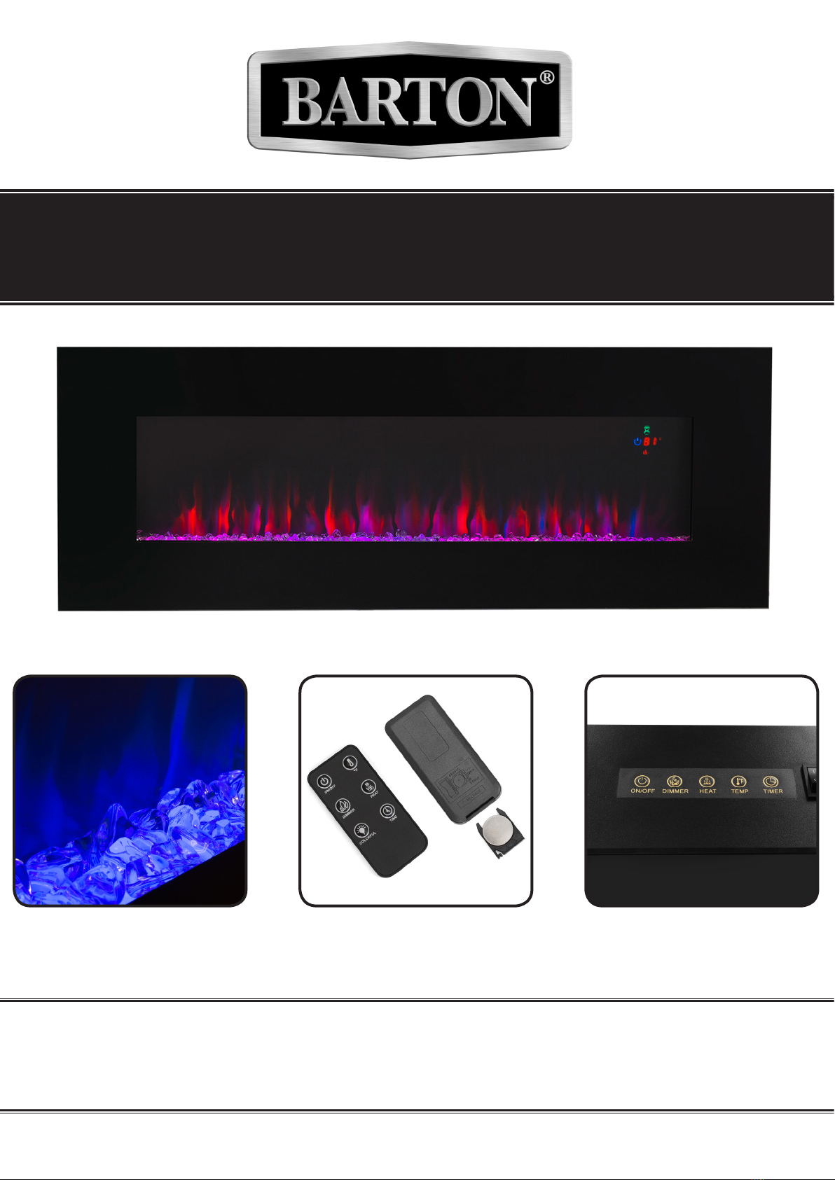
IMPORTANT SAFETY INFORMATION
GENERAL SAFETY WARNINGS
Read all safety warnings and instructions. Failure to follow the warnings and instructions may
result in electric shock, re and/or serious injury. Save all warnings and instructions for future
reference.
SAFETY
WARNING DO NOT use this product or any available optional equipment without rst completely reading
and understanding these instructions and any additional instructional material such as owner’s manuals,
service manuals or instruction sheets supplied with this product or optional equipment. When using an
electrical appliance, basic precautionas MUST be followed to reduce the risk of re, electric shock and
personal injury.
DO NOT mix old and new batteries.
1
DO NOT use rechargeable silver oxide cell batteries with the remote control unit.
DO NOT mix alkaline. Standard carbon-zine, or rechargeable batteries.
DO NOT switch the appliance on until is is properly installed as described in this manual.
DO NOT leave the replace unattented during use.
DO NOT operate the replace if it has a damaged cord or if it has any other malfunction.
DO NOT run the cable under carpets or rugs.
DO NOT allow the mains cable to hang over any sharp edges or hat surfaces.
This heater must be used on an AC supply only and the voltage marked on the heater must
correspond with the supply voltage.
Periodically check the cord for damage. NEVER use the appliance if there is any damage.
This heater must be used on an AC supply only and the voltage marked on the heater must
correspond with the supply voltage.
Risk of burns. This replace is HOT when in operation and heating element is ON. Power to the
replace should be turned off and the replace allowed to cool before servicing. To disconnect power
to the replace, turn controls to off, then remove plug from outlet.
Young children should be carefully supervised when they are in same room with replace. Toddlers,
young children and others may be susceptible to accidental contact burns. A physical barrier is
recommended if there are at risk individuals in the house. To restrict access to the replace, install an
adjustable safety gate to keep toddlers, young children and other at risk individuals away from the
replace and hot surfaces.
Clothing and other ammable material should not be placed on or near the replace.
Due to high temperatures, the replace should be located out of trafc and away from furniture and
draperies.
It is imperative that that the control compartments, circulating blower, and its passageway is the
replace is kept clean.
Under no circumstances should this replace be modied.