Baseband Technologies Stamp Module User manual

Baseband Technologies Inc. Title: Stamp-size Ultra Low-Power GPS Recei er Module User Guide Re . 1.0 Page 1
Stamp-size Ultra Low-Power
GPS Recei er Module
User Guide

Baseband Technologies Inc. Title: Stamp-size Ultra Low-Power GPS Recei er Module User Guide Re 1.0 Page 2
Table of Contents
1
O er iew .............................................................................................................................................................................................................. 3
1.1
Introduction ................................................................................................................................................................................................ 3
1.2
Scope .......................................................................................................................................................................................................... 3
1.3
Reference Documents ................................................................................................................................................................................ 3
1.4
Re ision History .......................................................................................................................................................................................... 3
2
Description of the Stamp Module ......................................................................................................................................................................... 4
2.1
O er iew ..................................................................................................................................................................................................... 4
2.2
Antenna ...................................................................................................................................................................................................... 4
2.3
Other Components and Connectors ........................................................................................................................................................... 4
3
Quick Start Guide For the Stamp Module ............................................................................................................................................................. 7
3.1
O er iew ..................................................................................................................................................................................................... 7
3.2
Authorization procedure ............................................................................................................................................................................ 7
3.2.1
Connect the Stamp Module ................................................................................................................................................................... 7
3.2.2
Identify the COM port ........................................................................................................................................................................... 8
3.2.3
Retrie e the Stamp Module ID ............................................................................................................................................................ 10
3.2.4
Request authorization code (AUTHCODE) ........................................................................................................................................... 10
3.2.5
Update AUTHCODE.............................................................................................................................................................................. 11
3.3
Initialization procedure ............................................................................................................................................................................. 13
3.3.1
Connect the Stamp Module ................................................................................................................................................................. 13
3.3.2
Identify the COM port ......................................................................................................................................................................... 13
3.3.3
Update the Ephemeris ......................................................................................................................................................................... 13
3.3.4
Initialize the Stamp Module ................................................................................................................................................................ 15
3.4
Operating procedure ................................................................................................................................................................................ 18
3.4.1
Connect the Stamp Module ................................................................................................................................................................. 18
3.4.2
Identify the COM port ......................................................................................................................................................................... 18
3.4.3
Programming the Stamp Module ........................................................................................................................................................ 18
3.4.4
Data collection..................................................................................................................................................................................... 20
3.4.5
Data Capture and Data Parsing............................................................................................................................................................ 21
4
Ad anced Operating Procedures ........................................................................................................................................................................ 22
4.1
GPSConsole commands ............................................................................................................................................................................ 22
4.1.1
@ANTENNA ......................................................................................................................................................................................... 22
4.1.2
@CHARGING ....................................................................................................................................................................................... 22
4.1.3
$DTR .................................................................................................................................................................................................... 22
4.1.4
@DYNAMICS ....................................................................................................................................................................................... 23
4.1.5
@FREQ ................................................................................................................................................................................................ 23
4.1.6
@KILL FIRMWARE ................................................................................................................................................................................ 23
4.1.7
@LEVEL ............................................................................................................................................................................................... 23
4.1.8
@OUTPUT ........................................................................................................................................................................................... 24
4.1.9
$PAUSE ................................................................................................................................................................................................ 24
4.1.10
@POS ............................................................................................................................................................................................. 25
4.1.11
@POWERSAVE ............................................................................................................................................................................... 25
4.1.12
@REPLAY........................................................................................................................................................................................ 26
4.1.13
$RTS ............................................................................................................................................................................................... 26
4.1.14
@SETTINGS .................................................................................................................................................................................... 26
4.1.15
@START ......................................................................................................................................................................................... 26
4.1.16
@STOP ........................................................................................................................................................................................... 27
4.1.17
$SYNCTIME .................................................................................................................................................................................... 27
4.1.18
@TIME ........................................................................................................................................................................................... 27
4.1.19
@UPDATE ...................................................................................................................................................................................... 27
4.1.20
@VERSION ..................................................................................................................................................................................... 27
4.1.21
@WAKE .......................................................................................................................................................................................... 28
4.2
Data processing for Modes 1 & 2 .............................................................................................................................................................. 29
4.3
Testing the Stamp Module ........................................................................................................................................................................ 30
4.3.1
Power consumption measurement ..................................................................................................................................................... 31
4.3.2
Tips ...................................................................................................................................................................................................... 34
4.4
Firmware update ...................................................................................................................................................................................... 35
4.4.1
Organize the necessary files ................................................................................................................................................................ 35
4.4.2
Connect the Stamp Module ................................................................................................................................................................. 35
4.4.3
Identify the COM port ......................................................................................................................................................................... 35
4.4.4
Erase the existing Firmware ................................................................................................................................................................ 35
4.4.5
Program the new Firmware ................................................................................................................................................................. 36
4.5
LEDs .......................................................................................................................................................................................................... 37
5
Schematics .......................................................................................................................................................................................................... 38

Baseband Technologies Inc. Title: Stamp-size Ultra Low-Power GPS Recei er Module User Guide Re 1.0 Page 3
1Overview
1.1 Introduction
The Stamp-sized Ultra Low-Power GPS Recei er Module (“Stamp Module”) was designed to
demonstrate the essential features of Baseband Technologies’ ultra-low power GPS (Global
Positioning System) recei er. The Stamp Module is also a ailable as a reference design that
includes the schematics and layout files to illustrate how easily and rapidly such a recei er can be
implemented, please contact info@basebandtech.com for further information. The Stamp Module
uses Maxim Integrated MAX2769 L1-band GPS RF front end IC (RFIC), and Baseband Technologies
ultra-low power GPS baseband processing firmware running on Maxim Integrated MAX32632 ARM
Cortex-M4™ microcontroller (MCU).
1.2 Scope
This document is a User Guide for the Stamp Module. It describes how to configure and operate
the module to e aluate the functionality and performance.
1.3 Reference Documents
[1] Baseband Technologies Stamp Module product webpage:
https://www.basebandtech.com/stamp
[2] Maxim Integrated MAX2769 webpage:
https://www.maximintegrated.com/en/design/reference-design-center/system-
board/7173.html
1.4 Revision istory
Revision
Date Description
1.0 April 2021 Initial Release

Baseband Technologies Inc. Title: Stamp-size Ultra Low-Power GPS Recei er Module User Guide Re 1.0 Page 4
2Description of the Stamp Module
2.1 Overview
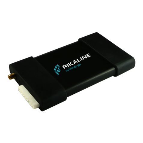
This section describes the arious connectors and basic functions of the GPS Stamp Module. A
photograph of the Stamp Module is shown in Figure 1.
Figure 1: Stamp Module (Left: Top-side, Right: Bottom-side)
2.2 Antenna
On the top-left side of the board, there is an U.FL type connector that is intended to connect to an
acti e antenna. Acti e antennas contain an integrated low noise amplifier (LNA) and thus require
acti e bias. This DC oltage to power the antenna is pro ided by the Stamp Module.
A recommended acti e antenna is made by Tallysman Wireless Inc. and can be purchased at
Digikey https://www.digikey.com/products/en?keywords=1526-1023-nd.
The acti e antenna is acti ated by using the @ANTENNA command (refer to section 4.1 for further
detail) and, when properly connected, the LED D1 will be illuminated but only during the period of
the data collection snapshot (e.g. 10ms). The MAX2769 RFIC pro ides the power to the antenna so
no bias-T or separate DC power supply is required.
2.3 Other Components and Connectors
The IC to the bottom right of the antenna connector, U1, is the MAX2769 RFIC. This is the circuitry
that down-con erts the GPS signals to digital samples for signal processing.
The IC to the right of the MAX2769, U2, is the MAX32632 microcontroller unit (MCU). The MCU is
where the ultra low-power GPS recei er firmware is hosted. Refer to Section 3 for details on using
the firmware.

Baseband Technologies Inc. Title: Stamp-size Ultra Low-Power GPS Recei er Module User Guide Re 1.0 Page 5
The IC on the bottom side, U3, is the MAX14690 Power Management IC (PMIC). This IC contains
se eral regulators which pro ide oltages required by other components. It also automatically
detects when 5V is being recei ed.
There are two 6-pin headers to interface with the Stamp Module.
The UART header (J5) is intended to connect the Stamp Module to a UART port. During the initial
testing phase, customers are ad ised to connect the Stamp Module to a PC using a FTDI or similar
de ice with 3.3V I/O. A suitable FTDI de ice is made by SparkFun Electronics and can be purchased
at Digikey https://www.digikey.ca/en/products/detail/sparkfun-electronics/BOB-13263/7675364.
IMPORTANT NOTES
The UART I/O voltage must be 1.8V to 3.3V.
The pin-out of the UART header is:
Pin-1: RTS
Pin-2: GND
Pin-3: CTS
Pin-4: RX
Pin-5: GND
Pin-6: TX
The PWR header (J4) is a multi-purpose connector.
Pin-1 (GND), Pin-3 (GND) and Pin-4 (5V) supplies power to the Stamp Module.
Pin-2 (\RESET) is hardware reset. When Pin-2 is pulled low briefly, the Stamp Module will perform
a hardware reset that is equi alent to turning the power ON/OFF.
Pin-5 (PWRSW) ser es as an ON/OFF switch to the Stamp Module when Pin-6 (BAT) is connected
to an optional rechargeable battery and is not powered by Pin-4 (5V).
To turn ON the Stamp Module, pull Pin-5 (PWRSW) low briefly.
To turn OFF the Stamp Module, pull Pin-5 (PWRSW) low for 12 seconds or more. This will
shutdown the Stamp Module completely and RTC time will be lost.
To control when the Stamp Module is awake or asleep, use the @WAKE command and the WAKE
pin (Pin-1 one the of the PGM/I2C header (J3)) (refer to section 4.1 for further detail). If the WAKE
pin is not connected, the Stamp Module will remain in the wake state.

Baseband Technologies Inc. Title: Stamp-size Ultra Low-Power GPS Recei er Module User Guide Re 1.0 Page 6
The rechargeable battery should be a Lithium-Ion type and up to 5V. The energy capacity of the
battery is up to the user. The battery is not supplied with the board. Howe er, there are many
suppliers of such batteries. One suggested product is https://solarbotics.com/product/50873/.
This is a 400 mAh, 3.7V Poly Lithium-Ion battery.
The pin-out of the PWR header is:
Pin-1: GND
Pin-2: \RESET
Pin-3: GND
Pin-4: 5V
Pin-5: PWRSW
Pin-6: BAT

Baseband Technologies Inc. Title: Stamp-size Ultra Low-Power GPS Recei er Module User Guide Re 1.0 Page 7
3Quick Start Guide For the Stamp Module
3.1 Overview
This section describes how to setup the Stamp Module to allow it to be used.
Prior to operating the Stamp Module, it must first be authorized and initialized. Figure 2 shows the
Authorization, Initialization, and Operating procedures.
3.2 Authorization procedure
3.2.1 Connect the Stamp Module
•If possible, disconnect all physical de ices that are currently attached to the host PC
(once section 3.2.2 is completed, you can reconnect those de ices to the PC)
•Connect the Stamp Module to the host PC ia a FTDI de ice (LED D6 should light up
followed by D4)
Figure
2
:
The
Authoriz
ation, Ini
tializ
ation & Ope
rating
P
rocedures

Baseband Technologies Inc. Title: Stamp-size Ultra Low-Power GPS Recei er Module User Guide Re 1.0 Page 8
3.2.2 Identify the COM port
•Download the Stamp Module utilities (utilities.zip) at the product webpage at
https://www.basebandtech.com/stamp
•Unzip the utilities to a folder of your choice (the example below created a folder
named “RefDesign” under the user’s Desktop)
•Type “cmd” at the address bar to open a command prompt window
Figure 3: Connecting the Stamp Module to the PC using a FTDI board

Baseband Technologies Inc. Title: Stamp-size Ultra Low-Power GPS Recei er Module User Guide Re 1.0 Page 9
•Type “mode” to display the COM port that the Stamp Module is connected to (the
example below shows the board is connected to COM6 of the host PC)

Baseband Technologies Inc. Title: Stamp-size Ultra Low-Power GPS Recei er Module User Guide Re 1.0 Page 10
3.2.3 Retrieve the Stamp Module ID
•At the command prompt window, type “cls” to clear the screen
•At the command prompt window, type “gpsconsole 6 getauthid” (replace the
number 6 with the number corresponding to the COM port of your PC.)
•At the command prompt window, type “dir” to confirm that a new file named
“getauthid_yyyymmddHHMMSS.log” has been created in the utilities folder (where
“yyyymmddHHMMSS” is a series of digits representing year, month, day, hour,
minute and second when the .log was generated.)
IMPORTANT NOTES
In all the examples in this document the COM port is 6 but the actual value to use
will depend on your PC and which USB port the board is connected to.
3.2.4 Request authorization code (AUT CODE)
•Open an internet browser, na igate to https://www.basebandtech.com/stamp, fill
out the AUTHCODE Request form and upload the
“getauthid_yyyymmddHHMMSS.log” file

Baseband Technologies Inc. Title: Stamp-size Ultra Low-Power GPS Recei er Module User Guide Re 1.0 Page 11
•Once the form is submitted, your ownership record will be updated and an email
with the following will be sent to you usually within one business day:
An AUTHCODE file called “authcode_XX-XX-XX-XX.gc” (where “XX-XX-XX-
XX” is the De iceID or the board de ice identification number)
A “loadkey_XX-XX-XX-XX.gc” (where “XX-XX-XX-XX” is the De iceID or the
board de ice identification number). Keep this file in a secured location, you
will need to update the firmware in the future.
Username
Password
3.2.5 Update AUT CODE
•If you ha e not recei ed your AUTHCODE after one business day, please check your
email spam folder followed by contacting us at info@basebandtech.com for
assistance.
•If you ha e recei ed your AUTHCODE ia email, sa e the “authcode_XX-XX-XX-
XX.gc” file to the utilities folder
•To reconnect the Stamp Module, repeat the same procedure as outlined in sections
3.2.1 and 3.2.2.
•At the command prompt window, type “cls” to clear the screen
•At the command prompt window, type “gpsconsole 6 authcode_XX-XX-XX-XX”

Baseband Technologies Inc. Title: Stamp-size Ultra Low-Power GPS Recei er Module User Guide Re 1.0 Page 12
•Confirm that the expiration date(s) of the authorized operating modes are
consistent with what you ha e purchased
•Confirm that a new file named “authcode_XX-XX-XX-XX_ddddddddddddd.log” has
been created in the utilities folder (where “XX-XX-XX-XX” is the De iceID of your
board and “ddddddddddddd” is a series of digits)
•Using a text file editor, open the “authcode_XX-XX-XX-XX_ddddddddddddd.log”
file to see the AUTHCODE and the expiration dates for the Stamp Module

Baseband Technologies Inc. Title: Stamp-size Ultra Low-Power GPS Recei er Module User Guide Re 1.0 Page 13
3.3 Initialization procedure
3.3.1 Connect the Stamp Module
•To reconnect the Stamp Module, repeat the same procedure as outlined in section
3.2.1
3.3.2 Identify the COM port
•To identify the port connected to the Stamp Module, repeat the same procedure as
outlined in section 3.2.2
3.3.3 Update the Ephemeris
•Type “cmd” at the address bar to open a command prompt window
•Type “getephemeris -s” to download the latest extended ephemeris data file to the
utilities folder

Baseband Technologies Inc. Title: Stamp-size Ultra Low-Power GPS Recei er Module User Guide Re 1.0 Page 14
•Type “gpsconsole 6 ephemeris” to inject the extended ephemeris to the Stamp
Module

Baseband Technologies Inc. Title: Stamp-size Ultra Low-Power GPS Recei er Module User Guide Re 1.0 Page 15
•Confirm the ephemeris file has been injected into the board with the message
“%EP EM,OK”
3.3.4 Initialize the Stamp Module
IMPORTANT NOTES
The initialization procedure is required for Modes 2 & 3 Only.
The initialization procedure must be performed prior to operating the Stamp
Module the first time OR if the board has travelled more than 100Km from the last
computed position.
The initialization procedure can be performed repeatedly without causing any harm
to the Stamp Module. If unsure repeat the initialization procedure.
The initialization procedure usually takes seconds to complete but many factors
could cause the initialization procedure to take up to 15 minutes to complete. To
reduce the time required for the initialization process use the @POS command to
define initial position and uncertainty as described in section 4.1.
•Connect the acti e antenna to the U.FL connector

Baseband Technologies Inc. Title: Stamp-size Ultra Low-Power GPS Recei er Module User Guide Re 1.0 Page 16
IMPORTANT NOTES
The placement of the GPS antenna is very important.
During the initial testing phase customers are advised to place the GPS antenna at
a location where it has a clear view of the open sky without any obstructions
nearby.
•Mount the antenna to a location where is has a full iew of the open sky
•Open the “init.gc” script file with a text editor
•Scroll down to the first @POS command. The @POS command can be used to
define an initial position and its uncertainty. When an initial position is entered, the
associated uncertainty should be within a 50Km radius of the initial position. If the
initial position is not known, set the initial position to any alue (e.g. Lat=0, Long=0,
height=0) and the uncertainty to 20000.
•Scroll down to the first @ANTENNA command. The @ANTENNA command can be
used to select between the acti e or passi e antenna inputs. The @ANTENNA
ACTIVE TEST command can also be used to test if the acti e antenna is connected
properly by detecting if there is current draw from the RFIC to the acti e antenna. If
so, LED D1 will be illuminated until the first data collection process (i.e. when the
“s” key is pressed which is a shortcut to toggle the @START/@STOP commands).
•Close the text editor (Optional: You may wish to sa e any changes you made to
“init.gc”)
•With the Stamp Module connected, LED D4 will be illuminated to indicate that it is
ready to accept commands.
•Type “gpsconsole 6 init” to start the Initialization process.
•Note that LED D4 will turn off, LED D1 will blink, and LED D5 will illuminate while
processing.
•The Initialization process can take anywhere between seconds to se eral minutes to
complete.
•The message “TCXO frequency offset = XXX z” (where XXX is the TCXO frequency
offset in Hz) in Green confirms the initialization procedure is successful.
•The gpsconsole utility will terminate once the initialization process is complete.
IMPORTANT NOTES
The ‘ESC’ and ‘s’ keys will not work during initialization process. To terminate
gpsconsole at any time one can press the ‘C’ key while holding the ‘CTRL’ key.

Baseband Technologies Inc. Title: Stamp-size Ultra Low-Power GPS Recei er Module User Guide Re 1.0 Page 17

Baseband Technologies Inc. Title: Stamp-size Ultra Low-Power GPS Recei er Module User Guide Re 1.0 Page 18
3.4 Operating procedure
3.4.1 Connect the Stamp Module
•To reconnect the Stamp Module, repeat the same procedure as outlined in section
3.2.1
3.4.2 Identify the COM port
•To identify the port connected to the Stamp Module, repeat the same procedure as
outlined in section 3.2.2
3.4.3 Programming the Stamp Module
•Type “cmd” at the address bar to open a command prompt window

Baseband Technologies Inc. Title: Stamp-size Ultra Low-Power GPS Recei er Module User Guide Re 1.0 Page 19
•Type “gpsconsole 6 setup” to program the Stamp Module using the sample
configurations defined in the setup.gc script (see section 4.1 for gpsconsole
commands)

Baseband Technologies Inc. Title: Stamp-size Ultra Low-Power GPS Recei er Module User Guide Re 1.0 Page 20
3.4.4 Data collection
Table of contents
