Basement Sentry STBB100Q User manual

1
© 2020. All rights reserved.
AUTOMATIC EMERGENCY
BACKUP SUMP PUMP
SYSTEM
MODEL #STBB100
Purchase Date
Questions, problems, missing parts? Before returning to your retailer, call our customer
service department at 1-800-742-5044, 7:30 a.m. - 5:00 p.m., EST, Monday - Friday.
ATTACH YOUR RECEIPT HERE
Español p. 13
SW1400 B
BasementSentry.com
AUTOMATIC EMERGENCY
BACKUP SUMP PUMP
SYSTEM
MODEL #STBB100Q

2
© 2020. All rights reserved.
PACKAGE CONTENTS
SAFETY INFORMATION
DESCRIPTION QUANTITY
A 12V Pump 1
B Battery Box 1
C Switch 1
D Charger 1
E 90º Elbow 1
F Pipe clamp 1
Please read and understand this entire manual before attempting to assemble, operate, or install the
product.
DANGER
• RISK OF CHEMICAL BURNS.
Battery acid is corrosive. Do not spill on skin, clothing or battery charger. Wear eye and head
protection when working with battery. Connect and disconnect DC output terminals only after
removing the charger from the AC outlet. Never allow the DC terminals to touch each other.
• FIRE/EXPLOSION HAZARD.
Keep sparks and flame (pilot light) away from battery.
• FIRE/EXPLOSION HAZARD.
Pump only clear water. Do not pump flammable or explosive fluids such as gasoline, fuel oil,
kerosene, etc. Do not use in a flammable and/or explosive atmosphere. Failure to follow these
warnings could result in death or serious injury and/or property damage.
• RISK OF ELECTRIC SHOCK.
These pumps have not been investigated for use in swimming pool or marine areas.
• RISK OF ELECTRIC SHOCK.
Always disconnect power source before attempting to install, service, or maintain the pump.
Never handle a pump with wet hands or when standing on wet or damp surface or in water. Fatal
electrical shock could occur.
• RISK OF ELECTRIC SHOCK.
Keep pump out of reach of children.
• PERSONAL INJURY OR PRODUCT DAMAGE MAY RESULT.
Failure to comply with instructions and designed operation of this product may void warranty.
Attempting to use a damaged pump can result in property damage, serious personal injury and/or
death.
A
B
C
D
E
F

3
© 2020. All rights reserved.
WARNING
• ELECTRICAL SHOCK ALERT.
Do not disassemble the motor housing. The motor has NO repairable internal parts and
disassembly may cause dangerous electrical wiring issues.
• ELECTRICAL SHOCK ALERT.
Before installing this product, have the electrical circuit checked by an electrician to ensure proper
grounding. All electrical installations must conform to the National Electric Code and all local
codes.
• ELECTRICAL SHOCK ALERT.
Connect the AC adapter to a properly-grounded 115 volt circuit equipped with a Ground Fault
Circuit Interrupter (GFCI) device. Make sure the electrical supply circuit is equipped with fuses or
circuit breakers with a minimum capacity of 15 amps.
• ELECTRICAL SHOCK ALERT.
Never use an extension cord.
• ELECTRICAL SHOCK ALERT.
Do not remove or replace the power cord.
• ELECTRICAL SHOCK ALERT.
Protect electrical cord from sharp objects, hot surfaces, oil, and chemicals. Avoid kinking the cord.
• ELECTRICAL SHOCK ALERT.
Do not lift pump by the power cord.
• PERSONAL INJURY ALERT.
Do not touch an operating motor housing. The motor is designed to operate at high temperatures.
• PERSONAL INJURY ALERT.
Release all pressure and drain all water from the system before servicing any component.
• PERSONAL INJURY ALERT.
Secure discharge line before starting pump. An unsecured discharge line can cause personal
injury and/or property damage.
• PERSONAL INJURY ALERT.
Wear safety glasses at all times when working with pumps.
• PROP65 WARNING FOR CALIFORNIA RESIDENTS:
Cancer and Reproductive Harm – www.P65Warnings.ca.gov
CAUTION
• PERSONAL INJURY OR PRODUCT DAMAGE MAY RESULT.
The AC adapter operates on 115 volts. Make certain that the power source conforms to the
requirements of your equipment.
• PRODUCT DAMAGE MAY RESULT.
The continuous operating water temperature for this pump must not exceed 104°F (40°C).
• PRODUCT DAMAGE MAY RESULT.
This pump is designed to pump water only. It has not been evaluated for pumping chemicals or
corrosive materials. This pump is not designed for pumping effluent or sewage and should not be
used in applications involving salt water or brine.
• PRODUCT DAMAGE MAY RESULT.
Inspect the pump regularly for damage and perform routine maintenance as needed. Remove any
debris that may build up around the float.
• PRODUCT AND/OR PROPERTY DAMAGE MAY RESULT.
This pump is not designed for continuous operation.

4
© 2020. All rights reserved.
PREPARATION
Estimated Installation Time: 2-4 hours
Materials required for assembly: Deep-cycle marine battery, discharge piping and fittings (PVC,
poly pipe or galvanized steel), ‘Y’ pipe, 1-1/2-in 45° elbow, 1-1/2-in check valve, 1-1/4” MNPT x 1-1/2”
PVC socket adapter and 2-step PVC glue system (primer and sealer).
GENERAL PUMP INFORMATION
SPECIFICATIONS
MODEL PERFORMANCE IN GALLONS PER MINUTE
0 FT. 5 FT. 10 FT. 14 FT.
STBB100 29 20 10 Shut Off
This pump is designed to be installed in a sump basin along with a primary, 115V sump pump
for removing clear drain water. It is not a substitute for a primary sump pump. It is designed to
temporarily backup the primary sump pump in the event of a power outage or 115V pump failure.
The sump basin must be at least 18-in deep by 14-in diameter.
This system is designed to work with a deep-cycle marine battery, either a ooded lead-acid battery
or a sealed, maintenance-free lead-acid battery. Use of an automobile battery instead of a deep-cycle
marine battery in this system will signi cantly reduce pump performance. Automobile batteries are not
designed for this type of application and will not stand up to repeated charge and discharge cycling.
Both the primary pump and DC backup pumps will require check valves in the discharge pipes for
proper operation.
NOTE: Pump must be submerged in water before operation. Running the pump dry will cause
damage and void the warranty.
NOTE: The alarm will sound after connecting the battery. It will continue to sound until all
connections are made and the oat switch is in the down position.
The pump will continue to run for an additional 10 seconds after the float has been lowered. The
alarm will continue to sound while the pump is working.
Place the battery in a cool, dry, well-ventilated area on a shelf or protective plywood board. If a carbon
monoxide (CO detector) is installed in the same area as the DC pump system, it must be at least
15 ft. away from the battery in order to avoid nuisance CO alarms. Refer to CO detector installation
guidelines for more information.
5
© 2020. All rights reserved.
INSTALLATION INSTRUCTIONS
NOTE: Install the battery backup system when the
primary pump is not needed. Read instructions and
prepare all supplies before beginning installation.
1. Verify that the existing 115V sump pump is in
good working order. It is best to use a primary
sump pump with a vertical oat switch. Pumps
with tethered oat switches require more space
and may interfere with the operation of the
backup sump pump switch.
Vertical
float
switch
1
2. Manually operate the primary sump pump to
remove as much water as possible from the
basin. Do not let the pump run dry.
3. Disconnect the primary sump pump from power
source before installing the DC pump.
WARNING: Never handle a pump with wet
hands or when standing on wet or damp
surface or in water. Fatal electrical shock
could occur.
115 V
GFCI outlet
3
115 V
GFCI Outlet
2

6
© 2020. All rights reserved.
4. Remove any dirt or accumulated debris from the
sump pit and surrounding area. Clean out the
vent hole in the discharge pipe.
NOTE: If the sump basin is larger than 18-in.
diameter, the DC pump can be installed with the
primary pump on the same level or slightly higher
than the primary pump. If the sump basin is smaller
than 18-in. diameter, the DC pump will be installed
above the primary sump pump.
5. Disconnect or cut the main discharge pipe and
separate the primary sump pump from the
discharge pipe. Remove the pump from the
sump basin.
115 V
GFCI outlet
5
DC pump
installed
above primary
pump
Less than 18”
Clean
vent hole
Remove
debris
4
INSTALLATION INSTRUCTIONS
7
© 2020. All rights reserved.
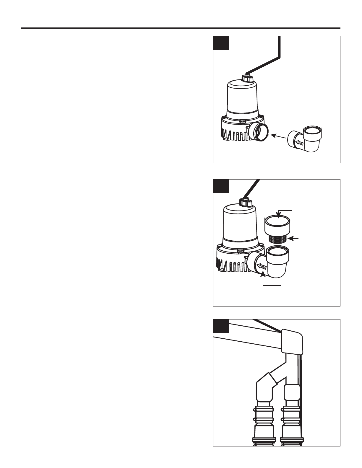
6. Wrap the DC pump discharge thread with Teflon
tape and attach a 1-1/4-in. FPT 90° elbow to the
discharge.
7. Wrap the thread of a 1-1/4-in. to 1-1/2-in
adapter (not included) with Teflon tape and
attach the adapter to the 90° elbow.
8. Install a “Y” pipe between the backup pump
discharge pipe and the primary pump discharge
1-1/2-in Slip
1-1/4-in NPT
Arrow points
toward pump
7
90° Elbow
6
INSTALLATION INSTRUCTIONS
Primary
Pump
Discharge
Backup
Pump
Discharge
Primary
Pump
Discharge
Backup
Pump
Discharge
Y Pipe
8
8
© 2020. All rights reserved.
10. Loosely attach the DC pump switch clamp to
the DC pump discharge pipe. Slide the switch
mounting bracket under the switch clamp.
Adjust the position of the switch so that the ‘ON’
level of the DC pump is above the ‘ON’ level of
the primary pump. Tighten the mounting clamp
of the DC pump switch in the correct location.
11. Place a fully-charged, deep-cycle marine battery
inside the battery box. Connect the leads inside
the battery box from the controller to the battery:
WARNING: Connecting the wires to the wrong
terminals on the battery may cause damage to the
controller.
Red (+) to battery Red (+)
Black (-) to battery Black (-)
NOTE: The alarm will sound after connecting
the battery. It will continue to sound until all
connections are made and the float switch is in the
down position.
NOTE: Be sure the battery box ventilation holes are
unobstructed. Battery control box must be set up in a
well-ventilated area, away from any smoke, flames or
pilot lights.
11
Clamp
Mounting
Bracket
DC Pump
Switch
10
INSTALLATION INSTRUCTIONS
NOTE: Assemble pipe and fittings without glue to
check for proper fit.
9. Connect pumps, pipe, check valve and fittings
to verify the position in the sump pit. Once fitting
is correct, glue all joints using 2-step PVC glue
and primer.
Both the primary pump and DC backup pumps
will require check valves in the discharge pipes
for proper operation. BOTH check valves should
be located between pump discharge and where
the discharge pipes are joined.
Check valve
located in
backup pump
discharge
Check valve
located in
primary
pump
discharge
Joined
discharge
pipes
9

9
© 2020. All rights reserved.
12. Connect system wires to the controller on the
top of the battery box lid.
a. Plug the pump wire into the port marked
‘PUMP’.
b. Plug the float switch wire into the port
marked ‘FLOAT’.
c. Plug the 12V charger into the port marked
‘ADAPTER’. Plug the charger into a 115V
GFCI protected power source.
Once the charger is plugged in, the LED lights
on the battery box should turn on.
ADAPTER
FLOAT
SWITCH PUMP
12
13. Test DC pump operation by lifting up the DC
float switch and holding it in place. The pump
‘Pump Status’ LED will show a continuous light
and the alarm will beep steadily. The pump
should start at this time. If it doesn’t start, check
all connections.
NOTE: The pump will continue to run for an
additional 10 seconds after the float has been
lowered. The alarm will continue to sound while
the pump is working.
14. Test all system connections by pressing the
‘RESET’ button for 1 - 4 seconds. The alarm
will sound. This will cause the system to run
a self-test and the DC pump will run for 3
seconds.
To silence the alarm, press the ‘RESET’ button,
hold for 4 - 8 seconds and release. The alarm
should stop.
After the system returns to normal status, the
alarm will automatically reset. SW1401 A
Press Reset
Red light on and alarm sounds:
Battery backup pump working
Red light slow flash and alarm sounds:
Pump wire connection problems or pump failed
Yellow light on:
Battery recharging
Yellow light slow flash and alarm sounds:
Power off or power adapter failed
Yellow light quick flash and alarm sounds:
Battery disconnected or DC fuse broken
Green light on:
System is normal RESET
14
SW1401 A
Pump Status LED
Red light on and alarm sounds:
Battery backup pump working
Red light slow flash and alarm sounds:
Pump wire connection problems or pump failed
Yellow light on:
Battery recharging
Yellow light slow flash and alarm sounds:
Power off or power adapter failed
Yellow light quick flash and alarm sounds:
Battery disconnected or DC fuse broken
Green light on:
System is normal RESET
13
INSTALLATION INSTRUCTIONS
10
© 2020. All rights reserved.
NOTE: Sump basin must be filled with water before
operation. Running the pump dry will cause
damage and void the warranty.
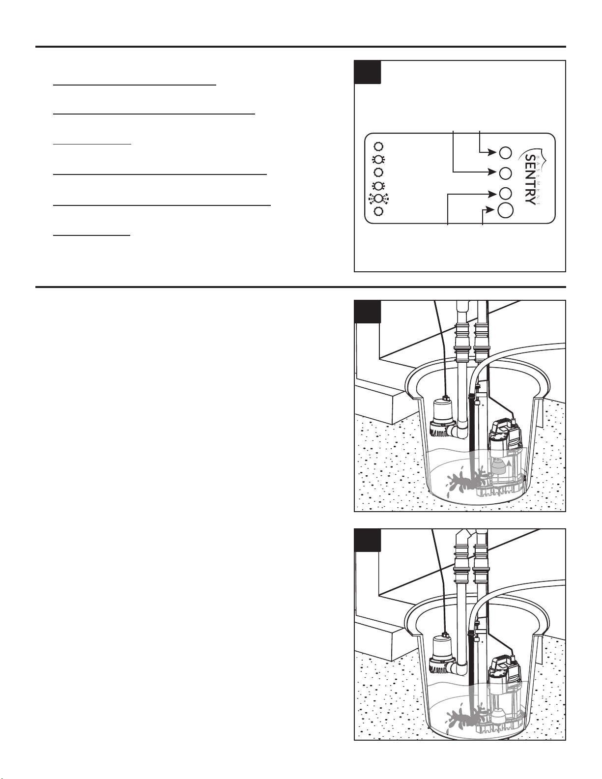
1. Verify 115V pump operation by filling the basin
with enough water to raise the float on the
primary sump pump. Pump should start and
remove water.
Unplug the 115V from the power source.
2. Test DC pump operation by refilling the sump
basin with water until the DC pump float moves
to the top of the float rod.
The DC pump should start and pump water out
of the sump basin. If pump does not operate,
check all wire connections.
2
1
OPERATION
15. LED Indicator Lights
Red light on and alarm sounds:
Battery backup pump is working
Red light slow flash and alarm sounds:
Pump wire connection problems or pump failure
Yellow light on:
Battery is recharging
Yellow light slow flash and alarm sounds:
Power off or power adapter failure
Yellow light quick flash and alarm sounds:
Battery is disconnected or DC fuse broken
Green light on:
The system is normal
SW1401 A
RESET
RedYellow
Green
Red light on and alarm sounds:
Battery backup pump working
Red light slow flash and alarm sounds:
Pump wire connection problems or pump failed
Yellow light on:
Battery recharging
Yellow light slow flash and alarm sounds:
Power off or power adapter failed
Yellow light quick flash and alarm sounds:
Battery disconnected or DC fuse broken
Green light on:
System is normal
15
INSTALLATION INSTRUCTIONS

11
© 2020. All rights reserved.
CARE AND MAINTENANCE
WARNING: Always disconnect pump from power source
before handling.
Once a month:
Press the reset button for 1-3 seconds to run a
self-test.
At least every three months:
• Remove any debris that may build up in the sump
basin to prevent it from interfering with the operation of
the float switch.
• Clean out the vent hole in the discharge pipe.
• Test system for operation.
Follow the battery manufacturer’s recommendations for
maintenance and safe use of the battery. Replace battery
as needed.
WARNING: An acid-filled standard lead-acid battery
contains sulfuric acid. Avoid contact with skin, eyes or
clothing.
Remove
debris
Clean out
vent hole
1
WARRANTY
This product is warranted for one year from the date of purchase or two years from the date of manufacture,
whichever occurs rst. Subject to the conditions hereinafter set forth, the manufacturer will repair or replace
to the original consumer, any portion of the product which proves defective due to defective materials or
workmanship. This warranty does not cover replacement parts for failure due to normal wear and tear. To
obtain warranty service, contact the retailer from whom the product was purchased. The manufacturer retains
the sole right and option to determine whether to repair or replace defective equipment, parts or components.
Damage due to conditions beyond the control of the manufacturer is not covered by this warranty. For warranty
questions or service, call 1-800-742-5044.
THIS WARRANTY WILL NOT APPLY: (a) To defects or malfunctions resulting from failure to properly install,
operate or maintain the unit in accordance with printed instructions provided; (b) to failures resulting from
abuse, accident or negligence; (c) to normal maintenance services and the parts used in connection with
such service; (d) to units which are not installed in accordance with normal applicable local codes, ordinances
and good trade practices; and (e) the unit is used for purposes other than for what it was designed and
manufactured.
RETURN OF WARRANTED COMPONENTS: Any item to be repaired or replaced under this warranty must be
returned to the manufacturer at such place as the manufacturer may designate, freight prepaid.
THE WARRANTY PROVIDED HEREIN IS IN LIEU OF ALL OTHER EXPRESS WARRANTIES, AND MAY
NOT BE EXTENDED OR MODIFIED BY ANYONE. ANY IMPLIED WARRANTIES SHALL BE LIMITED TO
THE PERIOD OF THE LIMITED WARRANTY AND THEREAFTER ALL SUCH IMPLIED WARRANTIES ARE
DISCLAIMED AND EXCLUDED. THE MANUFACTURER SHALL NOT, UNDER ANY CIRCUMSTANCES, BE
LIABLE FOR INCIDENTAL, CONSEQUENTIAL OR SPECIAL DAMAGES, SUCH AS, BUT NOT LIMITED TO
DAMAGE TO, OR LOSS OF, OTHER PROPERTY OR EQUIPMENT, LOSS OF PROFITS, INCONVENIENCE,
OR OTHER INCIDENTAL OR CONSEQUENTIAL DAMAGES OF ANY TYPE OR NATURE. THE LIABILITY
OF THE MANUFACTURER SHALL NOT EXCEED THE PRICE OF THE PRODUCT UPON WHICH SUCH
LIABILITY IS BASED.
This warranty gives you speci c legal rights, and you may have other rights which vary from state to
state. Some states do not allow limitations on duration of implied warranties or exclusion of incidental or
consequential damages, so the above limitations may not apply to you.
In those instances where damages are incurred as a result of an alleged pump failure, the
Homeowner must retain possession of the pump for investigation purposes.

12
© 2020. All rights reserved.
TROUBLESHOOTING
PROBLEM POSSIBLE CAUSE CORRECTIVE ACTION
Pump will not
start or run
(Red light
comes on briefly
and shuts off)
1. Wire connection issues 1. Check all the wiring connections.
2. Battery issue 2. Check for a low or defective
battery. Replace if needed.
3. Switch is stuck 3. Check to be sure the oat switch
is free to move up and down on
the oat switch rod.
4. Debris in pump inlet 4. Check for obstructions in pump.
Motor hums but
pump doesn’t
pump water
1. Battery issue 1. Check for a low or defective
battery. Replace if needed.
Flow rate is too
low
1. The discharge pipe length and/or
height exceeds the capacity of the
pump.
1. Re-configure the discharge pipe
length or height to fit system
specifications.
2. Low battery 2. Replace the battery or charge the
battery. It may take a few days to
bring the voltage on the battery
back up after heavy usage.
Pump cycles
frequently
1. The check valve located between the
discharge of the primary pump and the
backup pump tee is not installed or is
not working properly.
1. Install or replace check valve.
Pump runs
but water level
stays high
1. Battery issue 1. Check for a low or defective
battery. Replace if needed.
2. If power is restored to primary pump,
pump may require service.
2. Check primary pump and service
or replace as needed.
Slow flashing
red light and
alarm.
1. Pump wire connection 1. Check to make sure pump is
properly plugged into the
controller.
Light and alarm
will not clear
when holding
2. Debris in impeller 2. Check if pump is moving water.
Pump may be seized. Check for
debris stuck in impeller.
the reset button. 3. Pump Problem 3. Replace pump if pump is not
moving water and no debris is
interfering with impeller.
NOTE: Battery and wall adapter power must be removed to clear this fault.
RISK OF ELECTRIC SHOCK.
Always disconnect power source before attempting to install, service, or maintain the pump. Never
handle a pump with wet hands or when standing on wet or damp surface or in water. Fatal electrical
shock could occur.
DANGER
Table of contents


