Basement Systems Sani Dry CSB User manual

Designed For Basement and Crawlspace Dehumidification
INSTALLER’S & OWNER’S MANUAL
HVAC INSTALLER: PLEASE LEAVE MANUAL FOR HOMEOWNER
© Copyright Basement Systems, Inc. TS-311b
www.basementsystems.com
SANIDRY CSB INSTALLER'S AND OWNER'S MANUAL
2SaniDry CSB Installer’s & Owner’s Manual 3SaniDry CSB Installer’s & Owner’s Manual
Table of Contents
Precautions ...............................................................................1
1. Intended Application ..............................................................2
2. Registrations .........................................................................2
3. Specifications ........................................................................3
4. Unit Assembly ........................................................................3
4.1 Installing Feet ......................................................................3
4.2 Attaching Drain Hose ...........................................................3
5. Installation .............................................................................3
5.1 Location ..............................................................................3
5.2 Electrical Requirements .......................................................4
5.3 Condensate (Water) Removal ...............................................4
6. Operation ...............................................................................4
6.1 Humidity Control Adjustment ...............................................4
6.2 Defrost Cycle .......................................................................4
6.3 Blower (Fan) Switch .............................................................4
7. Maintenance ..........................................................................5
7.1 Air Filter ...............................................................................5
7.2 Cleaning and Replacement ..................................................5
7.3 Removing Filters ..................................................................5
7.4 Installing Filters ...................................................................5
8. Service ..................................................................................5
8.1 Technical Description ...........................................................5
8.2 Troubleshooting ...................................................................6
9. Accessory/Replacement Parts ................................................6
Warranty.....................................................................................7
Precautions
• Do not operate the unit with a cut or frayed power cord.
• Do not unplug the unit by pulling on the cord. Grasp the plug
firmly and pull it out of the wall socket or power receptacle.
• Always use a grounded outlet.
• Never operate electrical equipment near or in standing water.
• Do not stick your ngers or other objects through the safety grills.
• Do not restrict airow into or out of the unit. This may cause the
unit to overheat.
• Unit should never be serviced or cleaned while it is plugged in.
• Do not sit or stand on the unit or use as a shelf or table.
• Before leaving the SaniDry CSB unattended, ensure children do
not have access to the equipment. Do not allow children to play
with or near the unit or in its air ow.
• The SaniDry CSB is designed to be installed indoors only.
Read the installation, operation and maintenance instructions
carefully before installing and using this unit. Proper adherence to
these instructions is essential to obtain maximum benefit from your
Santa F.e dehumidifier.
Read and Save These Instructions
WARNING! — This symbol means important
instructions. Failure to heed them can result in serious
injury or death.
CAUTION! — This symbol means important
instructions. Failure to heed them can result in injury or
material property damage.
1. Intended Application
The SaniDry CSB is intended for installation in crawl spaces or
basements that experience short or long-term high humidity
conditions; however, the attractively designed unit can be placed in
almost any residential setting where dehumidification is desired. Use
in non-residential applications and pool areas will void warranty.
The SaniDry CSB is designed to operate in temperatures between
56° and 95°F. Temperatures outside of these ranges may affect
dehumidifier performance.
In order to efficiently control the humidity levels, the area in which
the dehumidifier is to be placed must be free of water intrusion or
excessive fresh (outside) air infiltration. Before installing the SaniDry
CSB, water intrusion and air infiltration problems should be addressed.
2. Registration
The SaniDry CSB conforms to UL STD 474 and CSA standard C22.2 No. 92
3. Specifications
Part Number: 4025701
Blower: 240 CFM @ 0.0" WG
Power: 700 watts @ 80°F and 60% RH
Supply Voltage: 115 volt – 1phase – 60 Hz
Current Draw: 5.9 Amps
Energy Factor: 2.60 L/kWh
Operating Temp.: 45°F Min., 95°F Max.
Sized for: 2200 Sq. Ft. - Typical
Miniumum Performance at 80°F and 60% RH
Water Removal: 90 Pints/Day
Efficiency: 5.5 Pints/kWh
Air Filter: MERV-11
Efficiency: Standard 65% Efficient, ASHRAE Dust Spot Test
Size: Size: 12"x 12"x 1"
Power Cord: 9', 110-120 VAC, Ground
Drain Connection: 5/8" hose barb or 3/4" FPT
Drain Hose: 5/8" ID x 8' Direct Gravity Drain Hose
SaniDry CSB Dimensions
Unit with Duct Kit: Shipping
Width: 14-1/2"14-1/2" 22"
Height: 19"w/o feet 22-1/4"w/o feet 25"
Depth: 33"40-3/8" 39"
Weight: 71 lbs 78-1/2 lbs

SANIDRY CSB INSTALLER'S AND OWNER'S MANUAL
2SaniDry CSB Installer’s & Owner’s Manual 3SaniDry CSB Installer’s & Owner’s Manual
4. Unit Assembly
4.1 Installing Feet (Optional)
Included with your SaniDry
CSB are four leveling feet. It is
important to level the unit for
proper draining. (See section
5.1.4, Figure 6)
Installing Leveling Feet
See Figures 2 and 2a for installing leveling feet.
1. Lay down a protective pad (pillow, blanket, etc.).
2. Carefully turn unit onto side opposite filter opening and drain
port.
3. Align leveling foot shaft with one of the four threaded hole
locations as shown in Figure 2.
4. Screw each leveling foot in ten revolutions.
5. Carefully bring unit to upright position.
6. Level unit for proper drainage as described in section 5.1.4
(Figure 6) of this manual.
7. Wait 10 minutes before operating.
CAUTION!
Note: Operating the unit immediately after bringing it to an upright
position can possibly damage the compressor. A short amount
of time is needed to allow the oil to return to it’s reservoir for
lubrication.
4.2 Drain Hose
Take drain hose off of drain port. With scissors, cut one inch off of
hose end to eliminate dented area. Place drain hose end on drain
port until fully seated. Refer to Section 5.1.4 regarding proper
drainage.
5. Installation
5.1 Location
The SaniDry CSB can be installed in a variety oocations to meet
the owner’s needs, but should beinstalled directly in the area to be
dehumidified. Other considerations include:
1. Providing access to a 115 VAC power outlet (10' power cord
is provided).
2. Locating near a oor or other suitable drain (8' drain hose
included).
3. Do not install the SaniDry CSB with the intake or exhaust of
the unit within 1' of a wall or other obstruction. Do not place
the unit where curtains or debris can be drawn onto the
intake and restrict airow. Do not operate in standing water
or place the unit near open water. Refer to Figure 5.
4. The SaniDry CSB drains via a gravity system. A level
indicator has been included near the intake of the unit.
To ensure the unit will drain properly, the unit should be
positioned so the level bubble appears in the non-shaded
area of the level indicator as shown. Refer to Figure 6. If
the unit is placed on an unlevel surface, adjust leveling feet
using a crescent wrench or 7/16" open wrench. Move handle
end of wrench from left to right to lower one foot. Adjust all
four feet underneath the unit until bubble in the level dial is
in the correct position. Failure to level the unit may result
in leakage or improper drainage. See Section 4.2 regarding
drain hose installation.
Figure 2: Insert leveling feet in
locations
Figure 2a: Screw each leveling
foot in ten revolutions
Figure 1: Four leveling feet
Figure 3: Drain port Figure 2a: Drain hose position
Figure 5: Installing SaniDry CSB in area with proper clearance.
Figure 6: Level bubble should be in indicator area for proper drainage.

SANIDRY CSB INSTALLER'S AND OWNER'S MANUAL
4SaniDry CSB Installer’s & Owner’s Manual
5.2 Electrical Requirements
The SaniDry CSB plugs into a common grounded outlet on a 15-
Amp circuit. While operating, it draws less than 7 amps @ 80°F,
60% RH and less than 6 amps @ 75°F, 50% RH. Use of a ground
fault circuit interrupter (GFCI) protected circuit is recommended.
The unit should not be used in areas prone to ooding.
5.3 Condensate (Water) Removal
The SaniDry CSB drains via a gravity system - it is not able to
push condensate (water) uphill. The drain hose must run at or
downhill toward the drain location. Be sure the hose is not kinked
or otherwise restricted so that water can pass through it. Improper
hose installation may result in water leakage.
To increase the efficiency of the unit, position the hose to create a
“trap” as shown in Figure 8. By creating a trap, it will hold a small
amount of water. Position the trap on the hose approximately 12" to
20" away from the unit. Check hose regularly to ensure it is clear and
water is draining properly.
If oor drain is not easily accessible, a condensate pump kit with a
20' hose is available. Refer to page 5 for ordering accessories.
6. Operation
6.1 Humidity Control Adjustment
The humidity control is an adjustable switch that turns the
dehumidifier on and off. It turns on when the relative humidity of
the air in which it is located rises to the dial set point. It turns off
when the RH drops 5% below the set point.
Approximate Humidity Levels Per Setting
“Dry” 35% to 45% Relative Humidity
“Normal” 45% to 55% Relative Humidity
(Recommended for most applications)
“Humid” 55% to 65% Relative Humidity
The dehumidifier will run continuously until the relative humidity
(RH) is reduced to the humidity control dial setting. There is no
benefit to setting the humidity control to “dry” in rooms under 65°;
doing so will result in long periods of ineffective dehumidifier run
time.
Once the dial has been set to the desired level of humidity control,
the SaniDry CSB will maintain the same percentage of relative
humidity regardless of room temperature.
To turn the unit off, position the humidity dial to the far left and set
fan control to “auto.”
6.2 Defrost Cycle
An automatic defrost thermostat is attached to the refrigerant
tubes inside the unit. It will automatically shut the compressor
off if excessive frost forms on the evaporator coil. The blower
will continue to run, causing air to ow through the evaporator
coil and melt the ice. When the ice has melted, the evaporator
temperature will rise and the thermostat will automatically restart
the compressor. During this process, cool air may be coming out of
the unit.
6.3 Electrical Requirements
Turning the fan switch “FAN ON” will cause the unit’s internal
blower to run continuously, whether the unit is dehumidifying or
not. This function is desirable if the unit is used for air circulation
or ltration. Turning the fan switch to “FAN
AUTO” will cause the unit’s internal blower to
run only while the unit is dehumidifying.
SANIDRY CSB INSTALLER'S AND OWNER'S MANUAL
5SaniDry CSB Installer’s & Owner’s Manual
7. Maintenance
CAUTION!
NOTE: Do not operate the unit without the proper filter or with
a less effective filter. The heat exchange coils inside the unit
could become clogged, resulting in a loss of effectiveness
and/or efficiency and may require disassembly to clean.
7.1 Air Filter
The SaniDry CSB ships with a standard MERV-11 65% 1"
pleated fabric filter and a 1/4" aluminum framed pre-filter
installed. Operating the unit with a dirty or obstructed filter will
reduce dehumidifier capacity and efficiency and may cause the
compressor to cycle on and off unnecessarily.
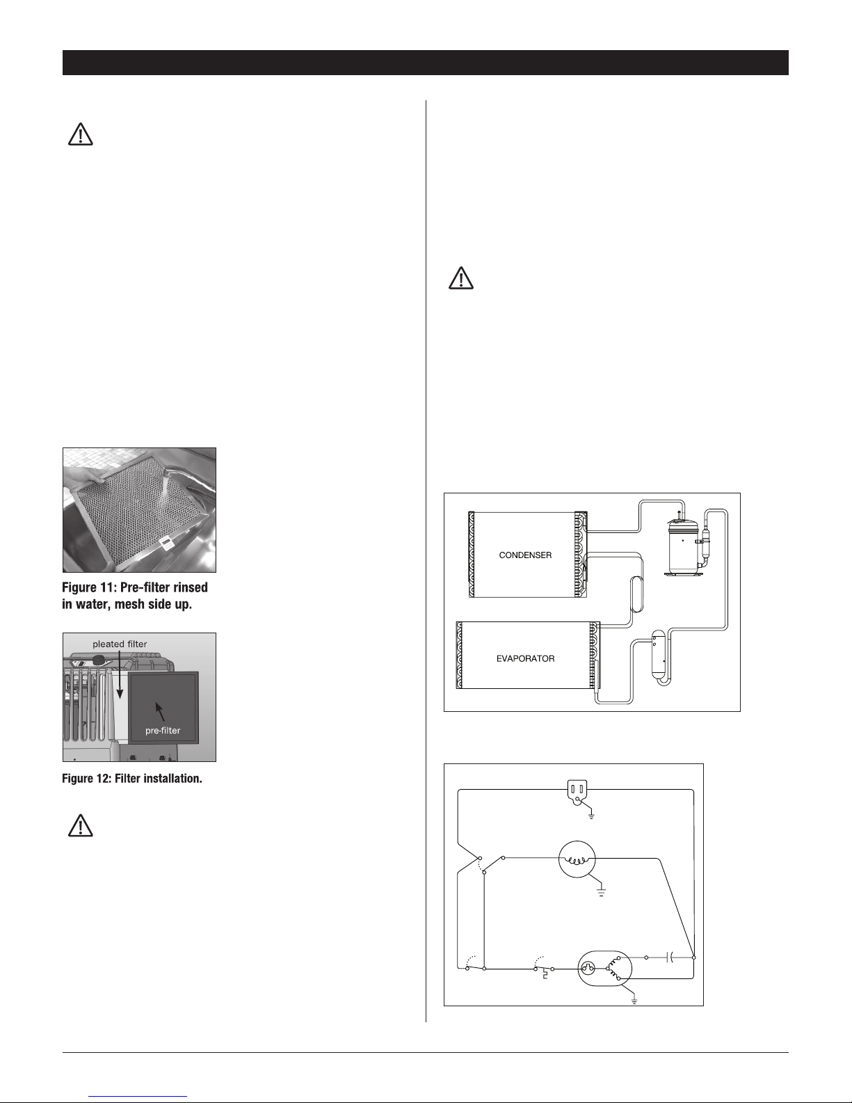
7.2 Cleaning & Replacement
Check filters every six months. Clean and/or replace when filters are
visibly dirty. See cleaning instructions below. For replacement filters
call your local Basement Systems dealer.
The 1/4" washable pre-filter
should not to be discarded.
Inspect the pre-filter for debris,
dirt, or other obstructions at
the same time the 1" pleated
fabric filter is checked. Wash the
1/4" pre-filter every time the 1"
pleated fabric filter is replaced. To
clean the 1/4" pre-filter, remove
filter from the unit, rinse the 1/4"
pre-filter in water with the water
owing through the aluminum
support mesh side. Refer to
Figure 11. Allow the filter to dry
completely before reinstalling.
Reinstall the filters per the
instructions below or on the tag
located on the 1/4" pre-filter.
CAUTION!
NOTE: Failure to follow filter handling instructions may result
in improper function of the dehumidifier and cause premature
filter wear.
7.3 Remove Filters
1. Gently remove the 1/4" pre-lter by pulling on the tab
attached to the filter.
2. Gently remove the 1" pleated fabric lter by pulling it out
of the unit.
7.4 Installing Filters
1. Gently slide 1" pleated lter into lter slot. Do not force.
If resistance is felt, check alignment for obstructions or
debris inside the filter housing.
2. Gently slide 1/4" pre-lter to left of 1" pleated lter.
Do not force. If resistance is felt, check alignment for
obstructions or debris inside the filter housing.
8. Service
WARNING!
Servicing the SaniDry CSB with its high pressure refrigerant
system and high voltage circuitrypresents a health hazard which
could result in death, serious bodily injury, and/or property
damage. Only qualified service people should service this unit.
8.1 Technical Description
The SaniDry CSB uses a refrigeration system similar to an air
conditioner’s to remove heat and moisture from incoming air and
add heat to the air that is discharged. Hot, high pressure refrigerant
Figure 13: SaniDry CSB refrigeration system.
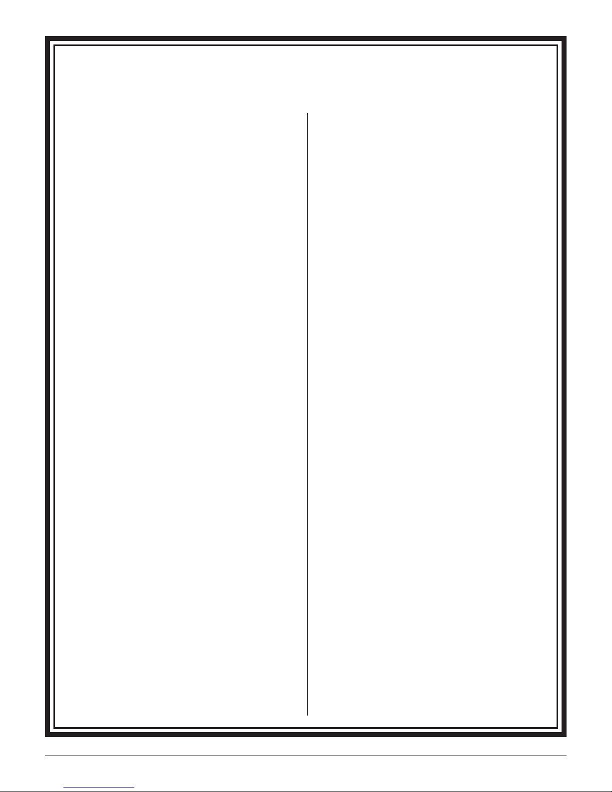
115 VAC, 60 Hz, SINGLE PHASE
BLK
BLK WHT
WHT
GRN
GRN
YEL
RED
FAN SWITCH
DEFROST
THERMOSTAT
FAN MOTOR
COMPRESSOR
3
1
2
BLK BLK
BLU
ORG
S
CR
GRN
FAN ON
FAN AUTO
DEHUMIDISTAT
RUN
CAPACITOR
115 VAC, 60 Hz, SINGLE PHASE
BLK
BLK WHT
WHT
GRN
GRN
YEL
RED
FAN SWITCH
DEFROST
THERMOSTAT
FAN MOTOR
COMPRESSOR
3
1
2
BLK BLK
BLU
ORG
S
CR
GRN
FAN ON
FAN AUTO
NEW CONTROL
RUN
CAPACITOR
Wiring Before Changes Wiring After Changes
Figure 14: Wiring diagram.

SANIDRY CSB INSTALLER'S AND OWNER'S MANUAL
6SaniDry CSB Installer’s & Owner’s Manual
gas is routed from the compressor to the condenser coil. The
refrigerant is cooled and condensed by giving up its heat to the
air that is discharged from the dehumidifier. The refrigerant liquid
then passes through capillary tubing which cause the refrigerant
pressure and temperature to drop. It next enters the evaporator coil
where it absorbs heat from the incoming air and evaporates.
The evaporator operates in a ooded condition, which means
that all the evaporator tubes contain liquid refrigerant during
normal operation. A ooded evaporator should maintain constant
pressure and temperature across the entire coil, from inlet to outlet.
The mixture of gas and liquid refrigerant enter the accumulator
after leaving the evaporator coil. The accumulator prevents any
liquid refrigerant from reaching the compressor. The compressor
evacuates the cool refrigerant gas from the accumulator and
compresses it to a high pressure and temperature gas to repeat the
process.
8.2 Troubleshooting
No dehumidification. Neither blower, nor compressor run with fan
switch AUTO.
1 Unit unplugged or no power to outlet, circuit breaker
tripped.
2 Humidity control set to “Humid” setting.
3 Loose connection in internal wiring.
4 Humidity control is defective.
No dehumidification. Compressor does not run but blower runs
with fan switch AUTO and humidity control turned to ON.
1 Defrost thermostat open, ambient temperature too low.
2 Loose connection in compressor circuit.
3 Defective compressor overload.
4 Defective compressor or compressor run capacitor.
Blower runs with fan switch AUTO but compressor
cycles on & off.
1 Low ambient temperature and/or humidity causing unit
to cycle through defrost mode.
2 Defrost thermostat defective.
3 Defective compressor overload.
4 Defective compressor.
Blower does not run with fan switch in either position.
Compressor runs briefly but cycles on and off.
1 Loose connection in blower circuit.
2 Obstruction prevents impeller rotation.
3 Defective blower.
4 Defective blower switch.
Evaporator coil frosted continuously, low dehumidifying capacity.
1 Dirty air lter or air ow restricted.
2 Defrost thermostat loose or defective.
3 Low refrigerant charge.
If none of the above has fixed the issue, call the service department
at 1-800-533-7533.
9. Optional Accessories
4025845 Condensate pump kit
4026055 Duct connection kit
4026607 Leveling casters set (4)
9.1 Replacement Parts
4025568 Pleated Air Filter .88" x 11.75" x 11.75"
4025831 Pre-Filter
4021495 Control Knob
4025577 Hose, PVC, Clear, .625" diameter, 8’ long
4026450 Leveling Feet
4025569 Adapter, .625" Hose x .75" MNPT
For more information on the SaniDry CSB,
call 1-800-640-1500.
Limited Warranty. Therma-Stor, LLC (“Therma-Stor”) warrants
as follows: (i) the SaniDry CSB dehumidifier (“Product”) will
be free of material defects in workmanship or materials for a
period of four (4) years (“Four-Year Warranty”) following the
date of initial purchase of such Product by an original customer/
end user purchasing from Therma-Stor or an authorized reseller
(“Customer”); and (ii) the Product’s condenser, evaporator, and
compressor will be free of material defects in workmanship or
materials for a period of five (5) years following the date of initial
purchase of such Product by a Customer. For the purpose of
this limited warranty, Basement Systems, its Dealers and other
representatives shall be considered authorized resellers of the
Product.
Limitation of Remedies. CUSTOMER’S SOLE AND EXCLUSIVE
REMEDY UNDER THE ABOVE LIMITED WARRANTY AND THERMA-
STOR’S ENTIRE LIABILITY THEREUNDER, SHALL BE, AT THE SOLE
OPTION OF THERMA-STOR, REPLACEMENT OR REPAIR OF SUCH
PRODUCT OR ITS COMPONENTS (“COMPONENTS”) BY THERMA-
STOR OR THERMA-STOR’S AGENTS ONLY. REFRIGERANT, PIPING,
SUPPLIES, TRANSPORTATION COSTS, LABOR COSTS INCURRED
IN REPAIR OR REPLACEMENT OF SUCH COMPONENTS ARE NOT
INCLUDED. THIS DISCLAIMER AND EXCLUSION SHALL APPLY
EVEN IF THE EXPRESS WARRANTY AND LIMITED REMEDY SET
FORTH HEREIN FAILS OF ITS ESSENTIAL PURPOSE. CUSTOMER
ACKNOWLEDGES THAT NO REPRESENTATIVE OF THERMA-STOR
OR OF ITS AFFILIATES OR RESELLERS IS AUTHORIZED TO MAKE
ANY REPRESENTATION OR WARRANTY ON BEHALF OF THERMA-
STOR OR ANY OF ITS AFFILIATES OR RESELLERS THAT IS NOT IN
THIS AGREEMENT. Notwithstanding the above, during the term
of the Four-Year Warranty only, Therma-Stor will provide, free
of charge to Customer, all Components and labor (except costs
related to removal and installation of Product) required to fulfill its
obligations under such Four-Year Warranty.
Disclaimer of Warranties. EXCEPT FOR ABOVE LIMITED
WARRANTY, WHICH IS THE SOLE AND EXCLUSIVE WARRANTY
PROVIDED WITH RESPECT TO THE PRODUCT AND ITS
COMPONENTS, THERMA-STOR HEREBY DISCLAIMS ALL EXPRESS
AND IMPLIED WARRANTIES, INCLUDING, WITHOUT LIMITATION,
THE IMPLIED WARRANTIES OF MERCHANTABILITY AND FITNESS
FOR A PARTICULAR PURPOSE.
Warranty Limitations. The foregoing limited warranty extends
only to a Customer and shall be null and void upon attempted
assignment or transfer. A “defect” under the terms of the limited
warranty shall not include problems resulting from Customer’s
or Customer’s employees’, agents’, invitees’ or a third party’s
misuse, improper installation, improper design of any system in
which the Product is included, abuse, lack of normal care, failure
to follow written instructions, tampering, improper repair, or
freezing, corrosion, acts of nature or other causes not arising out
of defects in Therma-Stor’s workmanship or material. If a Product
or Component is replaced while under warranty, the applicable
limited warranty period shall not be extended beyond the original
warranty time period. The limited warranty does not cover any
costs related to changes to a Product or Component that may
be required by any codes, laws, or regulations that may become
effective after initial purchase of the Product by Customer.
Customer Responsibilities. As a further condition to obtaining
warranty coverage hereunder, the Customer must send a valid
warranty claim to Therma-Stor such that Therma-Stor receives
such claim prior to the end of the applicable warranty period.
Therma-Stor shall have no obligation hereunder with respect to
any claim received by Therma-Stor after the expiration of the
applicable warranty period. As a further condition to obtaining
warranty coverage hereunder, the Customer must present forms
of invoices evidencing proof of purchase of a Product. If such
invoices do not clearly indicate the date of initial purchase by
a Customer, the applicable Product’s date of manufacture will
be used instead of the date of initial purchase for the purpose
of calculating the commencement of the applicable warranty
period. Warranty service must be performed by Therma-Stor or a
servicer authorized by Therma-Stor. In order to obtain warranty
service, the Customer should call Therma-Stor at 1-800-533-
7533 and ask for the Therma-Stor Products Service Department,
which will then arrange for applicable warranty service. Warranty
service will be performed during customary, daytime working
hours. If the Product must be shipped for service, Customer shall
be solely responsible for properly packaging the Product, for all
freight charges, and for all risk of loss associated with shipment.
Limitation of Liability. IN NO EVENT SHALL THERMA-STOR,
IN CONNECTION WITH THE DESIGN, SALE, INSTALLATION, USE,
REPAIR, REPLACEMENT OR PERFORMANCE OF ANY PRODUCT,
COMPONENT, PART THEREOF OR WRITTEN MATERIAL PROVIDED
THEREWITH, BE LIABLE, TO THE EXTENT ALLOWED UNDER
APPLICABLE LAW, UNDER ANY LEGAL THEORY FOR ANY SPECIAL,
DIRECT, INDIRECT, COLLATERAL OR CONSEQUENTIAL DAMAGES
OF ANY KIND. NOTWITHSTANDING THE ABOVE LIMITATIONS AND
WARRANTIES, THE SOLE AND EXCLUSIVE LIABILITY OF THERMA-
STOR, REGARDLESS OF THE NATURE OR THEORY OF THE CLAIM,
SHALL UNDER NO CIRCUMSTANCES EXCEED THE PURCHASE
PRICE OF THE PRODUCT, COMPONENT OR PART UPON WHICH
THE CLAIM IS PREMISED.
Applicable Law and Venue. ANY ARBITRATION,
ENFORCEMENT OF AN ARBITRATION OR LITIGATION RELATED
TO THE PRODUCT WILL BE BROUGHT EXCLUSIVELY IN DANE
COUNTY, WISCONSIN, AND CUSTOMER CONSENTS TO THE
JURISDICTION OF THE FEDERAL AND STATE COURTS LOCATED
THEREIN, SUBMITS TO THE JURISDICTION THEREOF AND WAIVES
THE RIGHT TO CHANGE VENUE. CUSTOMER FURTHER CONSENTS
TO THE EXERCISE OF PERSONAL JURISDICTION BY ANY SUCH
COURT WITH RESPECT TO ANY SUCH PROCEEDING.
Miscellaneous. If any term or condition of this Limited Warranty
is found by a court of competent jurisdiction to be invalid, illegal
or otherwise unenforceable, the same shall not affect the other
terms or conditions hereof or thereof or the whole of this Limited
Warranty. Any delay or failure by Therma-Stor to exercise any
right or remedy will not constitute a waiver of Therma-Stor to
thereafter enforce such rights.
7SaniDry CSB Installer’s & Owner’s Manual
SaniDry CSB Dehumidifier Limited Warranty

Information in this document is subject to change without notice. No part of this document
may be reproduced or transmitted in any form or by any means, electronic or mechanical,
for any purpose, without the express written permission of Basement Systems.
© 2008 Basement Systems, Inc. All rights reserved.
60 Silvermine Road
Seymour, Connecticut 06483
Web: www.basementsystems.com
1-800-640-1500
Table of contents
Popular Other manuals by other brands


Nidec
Nidec RK-3E instruction manual

Red Sea
Red Sea REEFER Series Operation manual

Mityvac
Mityvac PNEUMATIVAC MV7300 manual

Siemens
Siemens 3AH Instructions, Installation, Operation, Maintenance

Clear-Com
Clear-Com ICS-21 instruction manual

NewLine
NewLine NEO ANGLE 6MM FRAMELESS Installation Instructions and Technical Information

Masterlock
Masterlock FHW40300EURHRO Instructions for use

Point Mobile
Point Mobile RF800 user manual

Master cool
Master cool Mini Twin Turbo Series operating instructions

Aqua Medic
Aqua Medic Mistral 50 ECO Operation manual

Graphtech
Graphtech SUPERCHARGER installation instructions
 H4101 user manual")
Silk'n
Silk'n Pure (Deluxe) H4101 user manual