manuals.online logo
Brands
  1. Home
  2. •
  3. Brands
  4. •
  5. MINOURA
  6. •
  7. Other
  8. •
  9. MINOURA BIKE TOWER User manual

MINOURA BIKE TOWER User manual

BIKE TOWER instructions manual /バイクタワー取扱説明書
Thank you for purchasing Minoura BIKE TOWER.
This is the bike storage stand which can hold 2 bikes on its
cradle hook at two different heights. If you add 2 more optional
cradles behind the pole, you can hold up to 4 bikes on a pole.
The main pole is fully length adjustable from 1.7 meter (5' 7")
to 3.1 meter (10' 2") between the oor and the ceiling of your
room. And the top rubber cup is spring loaded so you can install
BIKE TOWER at anywhere you need safely without any tool.
You can have enough storage space without worrying about the
damage to the ceiling.
IMPORTANT NOTES /注意していただきたいこと
• Please read this instructions manual carefully before use.
ご使用になる前にこの説明書をしっかりと最後までお読みください。
• BIKE TOWER is the storage stand for ordinary 2-wheel bicycles only. Do NOT use it for any other
purposes, for example, displaying heavy electric bikes or tandem bikes, attaching wall panel or using the
pole horizontally to hook down the bikes.
バイクタワーは通常の2輪自転車専用です。重い電動自転車やタンデム車などを取り付けたり,あるいは支柱を
水平に倒してそこに自転車をぶら下げるなど,この説明書で指示されていない用途には使用しないでください。
• BIKE TOWER is installed between the oor and ceiling using a strong spring and the tension this
provides. BIKE TOWER must be installed rmly on a solid oor and ceiling using a supporting beam
or load bearing area of the ceiling. Failure to do so may cause damage to your ceiling, bikes, BIKE
TOWER, and may cause personal injury.
バイクタワーは天井に対してバネで押し付ける力で設置されています。天井裏に梁が通り十分な強度を持っている
場所にのみ設置してください。また床もしっかりと安定している必要があります。強度不足の場所に設置すると,
天井を突き破ったり倒れたりして怪我や損害の原因となります。
!
!
!
Set the BIKE TOWER up vertically
from oor to ceiling. Make sure
the BIKE TOWER is not slanted.
Slanted installation may cause the
BIKE TOWER to fall down, causing
damage and/or injury.
バイクタワーは天井と床との間で
垂直に設置してください。傾いた
まま設置されると十分な安定を確
保できなくなり,何かの衝撃で外
れて転倒してくる恐れがあります。
そのため天井と床とは平行でなけ
ればなりません。
When setting the main telescoping
pole, make sure to extend it until the
red warning sign no longer shows. The
warning sign is located just below the
upper rubber cup.
バイクタワーの支柱長さをセットする際
は,上側カップの直下にある赤い部分が
見えなくなるまで,十分に支柱を伸ばし
てください。
赤い部分が見えているということは,ま
だ必要なだけ支柱を伸ばしきっていない
ということを意味します。
Red Warning
Sign /
赤色の部分が
見えていたら
ダメ
Set BIKE TOWER rmly against a
supporting beam or load bearing area
of the ceiling.
Failure to do so will cause damage to
your ceiling.
天井は,十分な強度を持つ梁が通って
いる場所を選んでください。
梁がない板のみの場所だと,バネの力
で天井を突き破ってしまう恐れがあり
ます。
Ceiling Supporting Beam /梁
Ceiling
Panel /
天井板
- Page 1 -
(ver.5.2 2009/10)
このたびは「バイクタワー」をお買い求めいただきまして,
ありがとうございました。
バイクタワーは2台の自転車を上下2段に保持できる省ス
ペース型の収納台で,オプションのクレードルセットを追
加することで,1本の支柱に最大4台までの自転車を一度
に保持することができます(表側2台/裏側2台)。
支柱は 1.7 m〜 3.1 mの間で自由に長さを調整することが
でき,天井と床との間に突っ張らせて設置します。
上側ゴムカップにはバネが内蔵されており,天井に孔をあ
けたりすることなく工具なしで簡単に設置・移動させるこ
とができます。
!
For your safety, we recommend you to attach your
BikeTower to a secure location with the supplied
plastic tie and self-tapping screw.
予期しない地震や不慮の事態による転倒を防止す
るため,バイクタワーは付属のケーブルを使って
しっかりした場所に固定すべきです。
Self-Tapping Screw (M3.5x16 or 25)
Use proper size one
タッピングビス M3.5x16 または 25
いずれかを使用
How To Setup Your BikeTower /バイクタワーの組み立て方
We call each parts as below /各部の名称
Cradle Support
クレードル取り付け枠
Angle Adjust Plate (projection is foreside)
角度調整板(突起がある方が前面)
Alloy Stay
アルミバー
Cradle Hook
クレードルフック
Upper Rubber Cup
上側ゴムカップ
Upper Pole
(Band Size: 40mm)
上支柱(細)
バンドサイズ 40mm
Pole Joint
中間ジョイント
Lower Pole
(Band Size: 45mm)
下支柱(太)
バンドサイズ 45mm
Bottom rubber Cup
下側ゴムカップ
Height Range /支柱高さ範囲:
1.7m (5' 7") – 3.1m (10' 2")
1Firstly, make sure the lower bolt on the Pole Joint is rmly tightend.
Loosen the upper bolt on the Pole Joint then extend the Main Pole.
After you t the Main Pole to the ceiling, tighten the bolt slightly to lock the Main
Pole temporally (you don't need to tighten it strongly at this moment). (see Fig. A)
まず最初に,中間ジョイントの下側のボルトをしっかり締め込んでおきます。
続いて上側のボルトを緩め,支柱を伸ばしていきます。
下支柱を床に付けた状態で上支柱を天井に向かって伸ばしていき,上側ゴム
カップが天井に触れたところで,いったん中間ジョイントのボルトを仮締め
します(まだここでは本締めする必要はありません)。(図A)
Tighten temporally
ボルトは仮締めの
まま
2Remove the Main Pole from the ceiling while keeping the pole length.
Extend the Main Pole 20mm more, then tighten the upper bolt on the Pole
Joint rmly to nish the pole length adjustment. (see Fig. B)
いったん支柱を天井と床の間から取り外します。このとき支柱の長さが
変わってしまわないように注意してください。
仮締めしたボルトを緩めてこの長さからさらにあと 20 ミリだけ支柱を
伸ばし,その位置で今度はしっかりと締め込みます。(図B)
!
A loose the bolt on the Pole Joint may cause the pole
to slide down when a bike is in the cradle.
Overtightening the bolt on the Pole Joint may cause
the plastic Main Pole break.
Make sure the pole joint bolt is snug and that the joint
will not move.
中間ジョイントのボルトの締め付けが緩いままだと,自
転車をクレードルに載せたときの荷重で上支柱がずり落
ちてきてしまいますので,しっかりと締め付けておいて
ください。
ただし極端な締め付けすぎはボルトや中間ジョイントを
破損させてしまう恐れがあるため,注意が必要です。
1. Loosen upper
bolt
 上側のボルト
を緩める
3. Tighten upper
bolt
 上側のボルト
を締める
2. Extend 20mm
20 ミリ伸ばす
Setting Up The Main Pole /支柱の長さ調整のしかた
(Fig. A)
(Fig. B)
- Page 2 -
- Page 3 -
Setting Up The Bike Cradle /クレードルの組み立て方
1
(Fig. C)
Install the Cradle Hook behind the Alloy Stay. (see Fig. C)
Adjust the distance and angle of the hooks to suit the bike frame.
まずクレードルフックをアルミバーに取り付けます。(図C)
クレードルフックが自転車を傷つけるのを防止するため,アルミバー
の背面に取り付けてください。
2Place the Angle Adjust Plate onto the Cradle Support, then put the Alloy Stay
on it. Fix these three parts rmly with the supplied M6x20 bolt into the upper
hole. (see Fig. D)
Screw the supplied M6x15 bolt into the lower hole, but you don't need to
tighten it so rmly until you nally decide the angle.
クレードル取り付け枠に角度調整板を重ね,その上にアルミバーを重
ねます。これら3つとも長い方のボルト(M6x20)で取り付けます。
角度調整板の長孔部分には短い方のボルト(M6x15)をねじ込みます。
これは今はまだ本締めしなくても構いません。(図D)
(Fig. D)
(Fig. E)
(Fig. H)
3
Alloy Stay /アルミバー
Cradle Hook
クレードルフック
M6x20 bolt / M6x20 ボルト
M6x15 bolt / M6x15 ボルト
Stainless Band Assy is top
ステンレスバンドは上側
Just putting onto the pole
フック部は支柱に当てる
Stainless Band (40mm or 45mm)
ステンレスバンド(40mm または 45mm)
Plastic Bracket
樹脂ブラケット
M6x30 Bolt
M6x30 ボルト
Flat Washer
平ワッシャ
90º
!
!
Install each Bike Cradle to the Main Pillar.
To install the Stainless Band Clip, follow the steps below;
1) Once disassemble the Stainless Band Clip.
2) Open the band and wind it around the Main Pillar.
3) Lap the band ends (see Fig. F). The end with a welded nut must be
inward. Make sure that both ends t each other. If not, adjust the
bending angle.
4) Attach the Plastic Bracket onto the band. It should be snapped in.
5) Put the bolt into the hole on the Alloy Stay, then screw into the bracket
gently.
6) Adjust the cradle height and angle and tighten the bolt rmly.
組み立てたクレードルを支柱に取り付けます。
ステンレスバンドの取り付けかたは以下の通りに行ないます。
1)いったんステンレスバンドを分解します。
2)バンドを開き,支柱に巻き付けます。
3)ナットが溶接されている側の端が内側になるようにして,
  バンドの両端を重ね合わせます(図F)。両方のバンド端がぴっ
  たりと重ね合わされていることを確認してください。もし曲がっ
  ていたらバンドを曲げ直して調節してください。
4)樹脂ブラケットをバンドにかぶせます。
5)M6x30 ボルトに平ワッシャを通し,クレードル受けの上側の 
  孔に通してから,樹脂ブラケット中央の孔に静かにねじ込みます。
6)フックの高さや角度を調節したら,ボルトをしっかりとねじ  
  込みます。
If the inside band end with welded nut has been angled
against the bolt, you won't be able to screw the bolt in.
Make sure the nut side end is properly set at right angle
to the bolt. (see Fig. G)
バンド端は両方ともきちんと重なり合っていなければなり
ません。もしナット側が曲がってしまっているとボルトが
ねじ込めません。
ボルトに対してナットが直角になっていることを確認して
ください。(図G)
Do not push the bolt so much when screwing in.
The band end will have to be bent and you are no longer
tighten the bolt.
ボルトをねじ込むとき,力を入れて押し込まないでくださ
い。ナット側のバンドが曲がってしまい,ボルトがねじ込
めなくなってしまいます。
(Fig. F)
(Fig. G)
!
There are two different sizes on
the Stainless Band; 40mm and
45mm. You must use 40mm on
the Upper Pole and 45mm on the
Lower Pole.
Each one has an engraved mark
as "40" or "45" on the band.
ステンレスバンドには 40mm と
45mm の2種類があります。
上支柱には 40mm を,下支柱には
45mm を使用します(兼用は不可)。
それぞれに「40」または「45」の
刻印で表示しています。
!
If the red Warning Sign is visible below the Upper Rubber Cup even
after following the above instructions, the pole extension is too short
and may cause the bikes to fall over.
Please start the installation process over again to insure proper set
up and that the red Warning Sign does not appear.
支柱を立てたとき,もし上側ゴムカップの下に赤い部分が見えていたとし
たら,まだ十分に支柱が伸ばし切れていません。そのままだと荷重でバイ
クタワーが外れて転倒してくる恐れがあり,危険です。
いったんバイクタワーを取り外し,正しく支柱の長さを調整してから設置
し直してください。
Make sure the BIKE TOWER is set up vertically with no slant.
Failure to do so may cause equipment or personal damage.
バイクタワーはどの方向から見ても垂直になるように設置してくだ
さい。斜めになったままだと荷重がかかったときに突然外れて転倒
してくる恐れがあります。
!
5The Bike Cradle is angle adjustable.
If you want to move the cradle, loosen the lower
bolt on the Angle Adjust Plate, change the angle
until the displayed bike will be horizontal as
much as possible, then tighten the bolt rmly
again. (see Fig. J & K)
最後に,自転車ができるだけ水平になるよ
うにクレードルの角度を調整します。
クレードルの角度を変えるには,角度調整
板の下側のボルトを緩め,適当な角度にな
るまでクレードル全体を持って回転させ,
最後にすべてのボルトをしっかりとねじ込
みます。(図J)
(Fig. J)
For More Information... /お問い合わせ先
(Fig. K)
Safe bike hooking position
安全な自転車のフック箇所
- Page 4 -
MINOURA North America MINOURA Japan Headquarters
(Only for U.S. residents) (for every world-wide customers)
1996 East Ave. Hayward, CA 94541 U.S.A. 1197-1 Godo, Anpachi, Gifu 503-2305 Japan
Phone 1-510-538-8599 Fax +81-584-27-7505
Fax 1-510-538-5899 Mail [email protected]
Mail [email protected] Web www.minoura.jp
株式会社 深谷産業     株式会社 箕浦
〒 460-0015 名古屋市中区大井町 1-38 〒 503-2305 岐阜県安八郡神戸町神戸 1197-1
Phone (052) 321-6571 Phone (0584) 27-3131
Fax (052) 332-3166 Fax (0584) 27-7505
Web www.fukaya-sangyo.co.jp Mail [email protected]
Made in Japan /日本製
If you have any questions or need help, you should contact the dealer where you purchased or the Minoura distributor in your country rst.
The distributor can be found on our web site. Only when you cannot get enough service, you can contact us.
もし何かご不明な点や不具合があった場合には,まず最初にこの商品をお買い求めになったショップにご連絡ください。
4
Installing Your BikeTower In Your Room /バイクタワーの設置のしかた
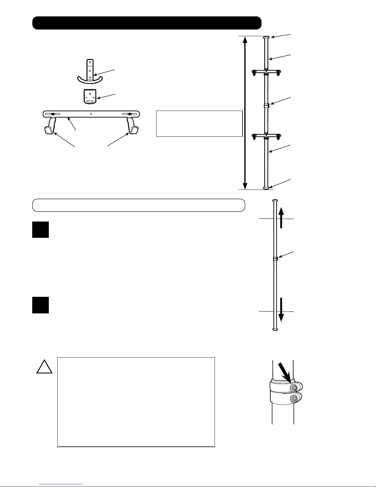
Set the BIKE TOWER between the ceiling and the oor.
First, put the Upper Rubber Cup against the ceiling, and push the Pole up to contact and
compress the inside spring.
Next, line up the Bottom Rubber Cup until the Main Pole is vertical. Once you line up
the top and bottom, pull down the Main Pole softly. (see Fig. I)
まず支柱を持ち,上側ゴムカップに内蔵されているバネを縮めるように力を入
れて天井に押し当てます。このとき支柱は斜めに傾いています。
そのまま下側をずらしていき,支柱を垂直に立てていきます。
完全に垂直になったら静かに支柱を下ろします。(図I)
(Fig. I)
1
2
自転車はできるだけ左右にずれないよう,フックをフレームの接合部などに掛けるようにします。(図K)

Other manuals for BIKE TOWER

1

Other MINOURA Other manuals

MINOURA M60-D - SCHEMA User manual

MINOURA

MINOURA M60-D - SCHEMA User manual

MINOURA ACTION BRIDGE User manual

MINOURA

MINOURA ACTION BRIDGE User manual

MINOURA BIKE TOWER User manual

MINOURA

MINOURA BIKE TOWER User manual

MINOURA RDA80 - SCHEMATICS User manual

MINOURA

MINOURA RDA80 - SCHEMATICS User manual

MINOURA VFS150 - SCHEMATICS User manual

MINOURA

MINOURA VFS150 - SCHEMATICS User manual

MINOURA M20-D - SCHEMA User manual

MINOURA

MINOURA M20-D - SCHEMA User manual

MINOURA M70-R - SCHEMA User manual

MINOURA

MINOURA M70-R - SCHEMA User manual

Popular Other manuals by other brands

Macally eNetPad user manual

Macally

Macally eNetPad user manual

Torklift C2204 Important owner-operator installation instructions

Torklift

Torklift C2204 Important owner-operator installation instructions

Ubisys 7047 Reference manual

Ubisys

Ubisys 7047 Reference manual

Augen Prizm user manual

Augen

Augen Prizm user manual

PALSON REVOLUTION brochure

PALSON

PALSON REVOLUTION brochure

Panasonic DBS 824 installation manual

Panasonic

Panasonic DBS 824 installation manual

ENERMAX AURORA datasheet

ENERMAX

ENERMAX AURORA datasheet

Heathkit HD-1410 instruction manual

Heathkit

Heathkit HD-1410 instruction manual

VLX 838R Operator's manual

VLX

VLX 838R Operator's manual

Feig Electronic ID RW02.ABC-A:ID RW02.ABC-B installation instructions

Feig Electronic

Feig Electronic ID RW02.ABC-A:ID RW02.ABC-B installation instructions

Samsung SGH x495 - Cell Phone - T-Mobile Service manual

Samsung

Samsung SGH x495 - Cell Phone - T-Mobile Service manual

enSkate Fiboard instruction manual

enSkate

enSkate Fiboard instruction manual

RIDGID FlexShaft K9-102 manual

RIDGID

RIDGID FlexShaft K9-102 manual

Marshall Amplification Major III Bluetooth - on ear user manual

Marshall Amplification

Marshall Amplification Major III Bluetooth - on ear user manual

Compaq 203039-B21 - Console Management Controller installation instructions

Compaq

Compaq 203039-B21 - Console Management Controller installation instructions

IBM HS21 XM BLADECENTER - 5160 FOR SPEC CPU2000 specification

IBM

IBM HS21 XM BLADECENTER - 5160 FOR SPEC CPU2000 specification

Automatic Systems PNG382 Field manual

Automatic Systems

Automatic Systems PNG382 Field manual

OVE ERIKA-LEA-SP32 manual

OVE

OVE ERIKA-LEA-SP32 manual

manuals.online logo
manuals.online logoBrands
  • About & Mission
  • Contact us
  • Privacy Policy
  • Terms and Conditions

Copyright 2025 Manuals.Online. All Rights Reserved.