BASENGREEN BR-RM-LV 6KWH User manual

Rack Mounted
Battery Pack
Installation & Operation Manual
BR-RM-LV 6KWH
BR-RM-LV 11.77KWH
BR-RM-LV 15.36KWH

Content
1. Preface ________________________________________________________________________________________ 01
2. Label Explanation _____________________________________________________________________________ 02
3. Product Description___________________________________________________________________________ 03
4. Product Advantages __________________________________________________________________________ 03
5. Product Technical Parameters________________________________________________________________ 04
5.1 Specification_______________________________________________________________________________ 04
5.2 Interface Overview ________________________________________________________________________ 05
5.3 Battery Management System _____________________________________________________________ 06
5.3.1 Overcharge Protection________________________________________________________________ 06
5.3.2 Overdischarge Protection ____________________________________________________________ 06
5.3.3 Overcurrent Protection _______________________________________________________________ 06
5.3.4 Over Temperature Protection ________________________________________________________ 06
5.3.5 Low Temperature Protection _________________________________________________________ 06
6. Installation and Configuration ________________________________________________________________ 07
6.1 Packing____________________________________________________________________________________ 07
6.2 Installation Diagram _______________________________________________________________________ 07
7. Connection____________________________________________________________________________________ 09
7.1 Precautions before Connecting The Inverter______________________________________________ 09
7.2 Precautions Before Connecting The Inverter with The Battery Pack in Parallel___________ 10
7.3 Dip Code Switch Definition and Setting___________________________________________________ 11
8. Operation _____________________________________________________________________________________ 12
8.1 Check Before Power on ___________________________________________________________________ 12
8.2 Power on __________________________________________________________________________________ 12
9. Operation of Upper System___________________________________________________________________ 15
9.1 Log in ______________________________________________________________________________________ 15
9.2 Operation of the Communication Protocol Switch________________________________________ 16
9.3 Communication Compatible List__________________________________________________________ 17
10. Storage ______________________________________________________________________________________ 18
11. Warning ______________________________________________________________________________________ 18

BASENGREEN, YOUR RELIABLE POWER 01
1. Preface
This manual will provide detailed product information and installation instructions for users of the
wall-mounted series products of SHENZHEN BASENGREEN TECHNOLOGY CO.LTD (hereinafter
referred to as BASENGREEN). Please read this manual carefully, and put this manual in a place where
you can install, operate, and obtain it conveniently.
The safety precautions mentioned in the manual do not represent all the safety matters that should be
observed, but are only supplementary to the safety precautions. When installing, operating, and
maintaining equipment, local safety regulations and norms should be followed. Only trained profession-
als can install, operate and maintain equipment. Our company does not assume any responsibility for
losses caused by violation of general safety operation requirements or violation of safety standards for
the design, production, and use of equipment. Installation and maintenance personnel must have
high-voltage and AC power operation skills. When installing, operating, and maintaining equipment,
they must not wear any conductive objects, such as watches, bracelets, bracelets, and rings, and
prevent moisture from entering the equipment.
High Voltage Danger
Safety Instructions
The high-voltage power supply provides power for the operation of the equipment. Direct contact or
indirect contact with high-voltage power supply through wet objects will cause fatal danger.
Use Professional Tools
Always use professional tools instead of personal tools when working with high voltage and AC power
Anti-static
The static electricity generated by the human body will damage the electrostatic sensitive
components on the board. Before touching the plug-in, circuit board or chip, make sure to take proper
anti-static measures.
Operate Attention
The power must be cut off first before operation, do not hot-line work.
DC short circuit Danger
The power system provides a DC-regulated power supply, and a DC short circuit will damage the
equipment and cause personal injury.
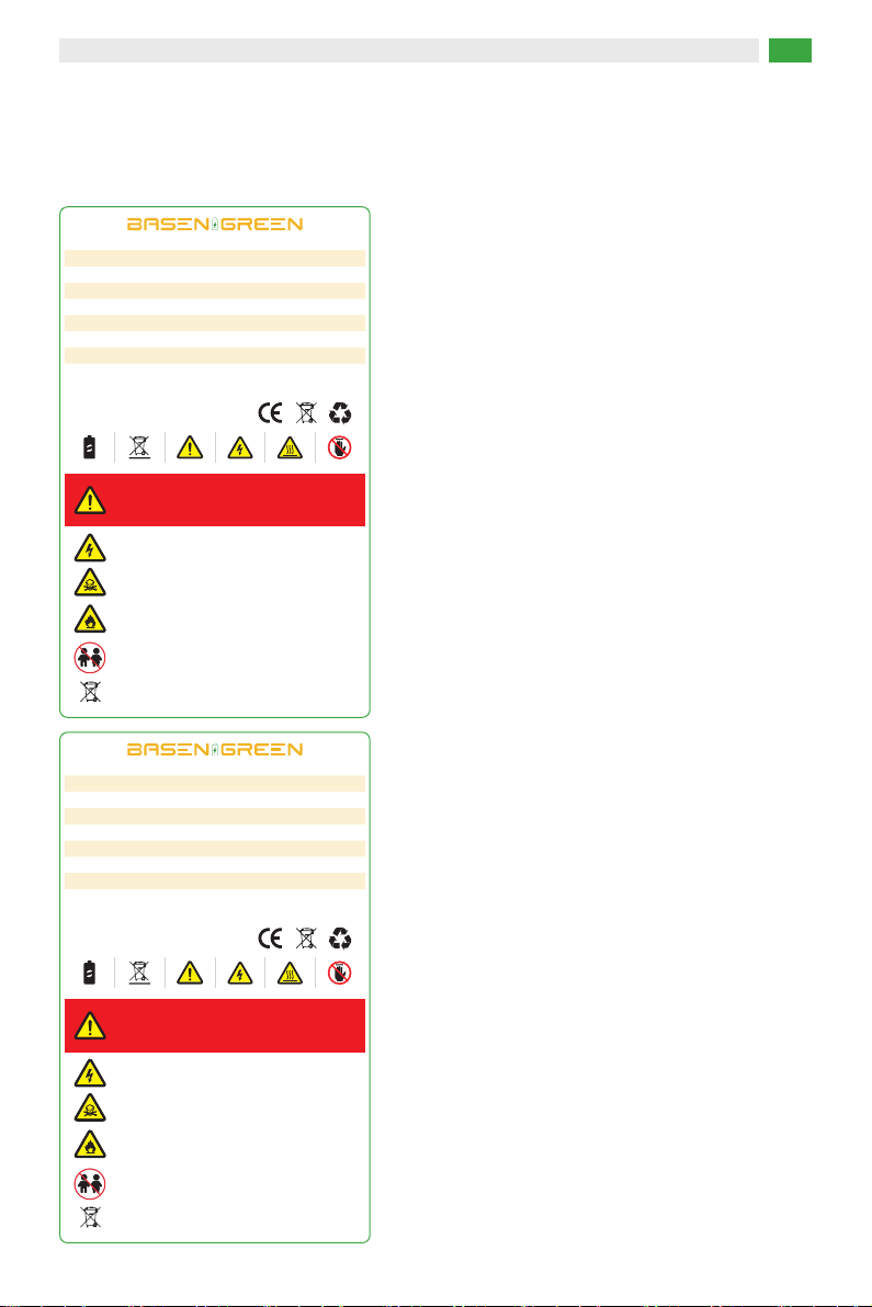
2. Label Explanation
The label contains the following information
BASENGREEN, YOUR RELIABLE POWER 02
Product Name Rechargeable LiFePO4 Battery
Product Model BR-RM-LV 11.77KWH
Battery Voltage Operation Range 43.2Vdc-58.4Vdc
Maximum Charge Current 200A
Maximum Discharge Current 200A
Rated Capacity 230Ah/51.2V/11776Wh
Ingress Protection IP55
Protective Class 1
CE UN38.3 IEC62619SN:
DANGER LOW DC VOLTAGE INSIDE
DANGER ARC FLASH & SHOCK HAZARD
DANGER
· Donotdisconnectordisassemblebynon-professionalpersonnel.
· Donotdrop,deform,hitorpiercewithsharpobjects.
· Donotplaceatachildrenorpettouchablearea.
· Donotplacenearopenflameorflammablematerial.
· Donotcoverorwraptheproductcase.
· Donotsitorputanyobjectonbattery.
· Avoiddirectsunlight.
· Avoidmoistureorliquid.
· TheproductingressProtection(IP)classisIP55.
· Makesurethegroundingconnectioniscorrectbeforeoperation.
· Followtheproductmanualtomakewringconnection.
· Ifleaking,fire,wetordamaged,switchoffthebreakeronDCside
andstayawayfrombattery.Donottouchtheleakingliquid.
· Contactyoursupplierwithin24hoursifanyfailurehappens.
Guangdong Basengreen New Energy Co.,Ltd
Product Name Rechargeable LiFePO4 Battery
Product Model BR-RM-LV 6KWH
Battery Voltage Operation Range 43.2Vdc-58.4Vdc
Maximum Charge Current 100A
Maximum Discharge Current 100A
Rated Capacity 120Ah/51.2V/6144Wh
Ingress Protection IP55
Protective Class 1
CE UN38.3 IEC62619SN:
DANGER LOW DC VOLTAGE INSIDE
DANGER ARC FLASH & SHOCK HAZARD
DANGER
· Donotdisconnectordisassemblebynon-professionalpersonnel.
· Donotdrop,deform,hitorpiercewithsharpobjects.
· Donotplaceatachildrenorpettouchablearea.
· Donotplacenearopenflameorflammablematerial.
· Donotcoverorwraptheproductcase.
· Donotsitorputanyobjectonbattery.
· Avoiddirectsunlight.
· Avoidmoistureorliquid.
· TheproductingressProtection(IP)classisIP55.
· Makesurethegroundingconnectioniscorrectbeforeoperation.
· Followtheproductmanualtomakewringconnection.
· Ifleaking,fire,wetordamaged,switchoffthebreakeronDCside
andstayawayfrombattery.Donottouchtheleakingliquid.
· Contactyoursupplierwithin24hoursifanyfailurehappens.
Guangdong Basengreen New Energy Co.,Ltd

Product Name Rechargeable LiFePO4 Battery
Product Model BR-RM-LV 15.36KWH
Battery Voltage Operation Range 43.2Vdc-58.4Vdc
Maximum Charge Current 200A
Maximum Discharge Current 200A
Rated Capacity 300Ah/51.2V/15360Wh
Ingress Protection IP55
Protective Class 1
CE UN38.3 IEC62619SN:
DANGER LOW DC VOLTAGE INSIDE
DANGER ARC FLASH & SHOCK HAZARD
DANGER
· Donotdisconnectordisassemblebynon-professionalpersonnel.
· Donotdrop,deform,hitorpiercewithsharpobjects.
· Donotplaceatachildrenorpettouchablearea.
· Donotplacenearopenflameorflammablematerial.
· Donotcoverorwraptheproductcase.
· Donotsitorputanyobjectonbattery.
· Avoiddirectsunlight.
· Avoidmoistureorliquid.
· TheproductingressProtection(IP)classisIP55.
· Makesurethegroundingconnectioniscorrectbeforeoperation.
· Followtheproductmanualtomakewringconnection.
· Ifleaking,fire,wetordamaged,switchoffthebreakeronDCside
andstayawayfrombattery.Donottouchtheleakingliquid.
· Contactyoursupplierwithin24hoursifanyfailurehappens.
Guangdong Basengreen New Energy Co.,Ltd
BASENGREEN, YOUR RELIABLE POWER 03
3. Product Description
This product is a lithium iron phosphate battery (LFP LiFePO4) composed of 16 cells in series. Which
is suitable for home energy storage systems. It can be customized according to customer needs to
meet diverse application scenarios and provide stable power for various equipment of users.
4. Product Advantages
a. Built-in Battery Management System (BMS): Overcharge, overdischarge, overcurrent, temperature
control, short circuit and other protection functions.
b. Passive Balance Function: There is a voltage equalization function during the charging.
c. High Cost Performance: High safety performance, long service life, stable and reliable quality.
d. Expandable: Equipped with RS232/ RS485/ CAN bus ports, support up to 15 units in parallel.

5. Product Technical Parameters
5.1 Specification
BASENGREEN, YOUR RELIABLE POWER 04
Item Specifications
51.2V
Nominal Voltage
BR-RM-LV
6KWH
Model
43.2V-57.6V
Operating Voltage
120AH
Nominal Capacity
6144Wh
Total Energy
1P16S
Configuration
58.4V
Charging Cut-off Voltage
43.2V
Discharge Cut-off Voltage
-20℃~60℃
Operation Temperature
20A
Standard Charging
Current
100A
Max Continuous
Charging Current
100A
Max Continuous
Discharge Current
440*435*222mm
Dimension
51KG
51.2V
BR-RM-LV
11.77KWH
43.2V-57.6V
230AH
11776Wh
1P16S
58.4V
43.2V
-20℃~60℃
50A
200A
200A
618*480*248mm
88KG
51.2V
BR-RM-LV
15.36KWH
43.2V-57.6V
300AH
15360Wh
1P16S
58.4V
43.2V
-20℃~60℃
50A
200A
200A
690*482*222mm
122KG
Net weight
e. Wide Working Temperature: -20℃to 60℃, excellent high-temperature discharge performance.
f. Convenient: Modular design, small size and lightweight, easy to install and maintain.
BASENGREEN, YOUR RELIABLE POWER 05
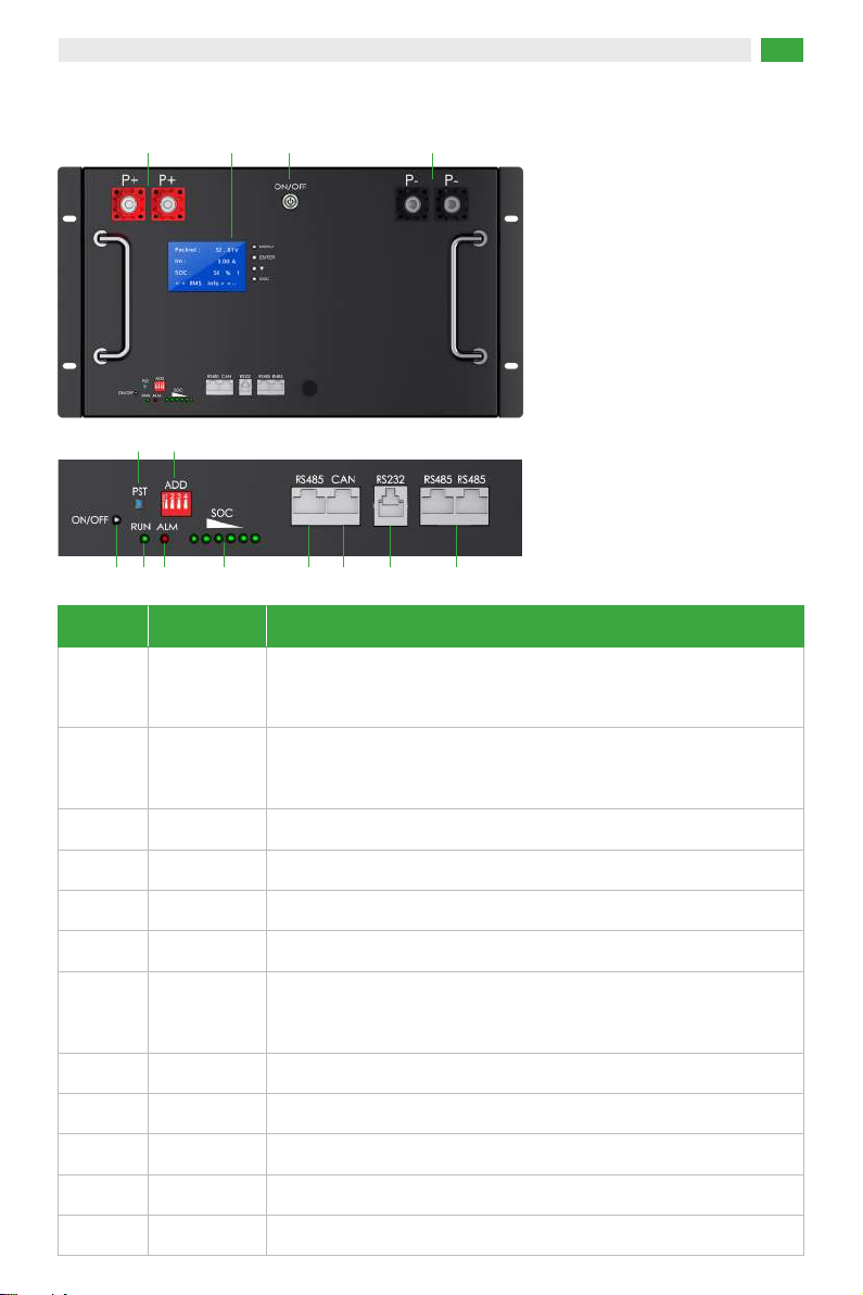
ItemPosition Description
The positive terminal of the battery, can be connected to the positive
pole of the inverter through a cable for DC output.
P+1
Manual-return switch button
RST4
5.2 Interface Overview
The negative terminal of the battery, can be connected to the
negative pole of the inverter through a cable for DC output.
Turn on then light-on, turn off then light-off
P-
2
Power Indicator3
Setting up battery parallel communication and inverter communication
ADD5
Indicating the normal operation status of the battery
RUN6
Indicating the abnormal state of the battery, if there is an low voltage
or over voltage, the alarm will sound.
Alarm
7
6 indicators, indicating the remaining power status.
SOC8
RS485 port for the inverter or the upper system communication
RS485 A9
CAN port for the inverter communication
CAN10
Communication port for the upper system.
RS23211
RS485 port for parallel communication
RS485 B/C12
3 6 7
54
13 14 2
1
8 9 10 11 12

BASENGREEN, YOUR RELIABLE POWER 06
5.3 Battery Management System(BMS)
5.3.1 Overcharge Protection
When the voltage of any single cell or whole battery pack is higher than the set value during the
charging, and the duration reaches the limited time, the system enters the over charging protection
state automatically, the charging MOS is turned off at the same time, and the battery cannot be
charged. After the voltage of each cell and the whole battery pack drops below the cell over charging
recovery value, the over charging protection state is released. It can also be released by discharging to
return to normal state.
5.3.2 Overdischarge Protection
When the voltage of any single cell or whole battery pack is lower than the set value during discharg-
ing, and the duration reaches the limited time, the system enters the overdischarge protection state,
the discharge MOS is turned off, and the battery cannot be discharged. After the overdischarge
protection of the battery pack occurs, it can be released by charging the battery pack.
5.3.3 Overcurrent Protection
During charging and discharging, when the current exceeds the set value of the protection current,
and the duration reaches the limited time, the system enters the overcurrent protection state, the
charging and discharging MOS will be turned off automatically, and the battery cannot be charged and
discharged, charging and discharging the battery pack can release the overcurrent protection state.
5.3.4 Over Temperature Protection
When the NTC detects the temperature of the battery cell surface is higher than the setting value of
over temperature protection during charging and discharging, the management system enters the
over temperature protection state, the charging or discharging MOS is turned off, and the battery pack
cannot be charged or discharged in this state.
5.3.5 Low Temperature Protection
When the NTC detects that the temperature of the cell surface is lower than the setting value of low
temperature protection during charging and discharging, the management system enters the low
temperature protection state, the charging or discharging MOS is turned off, and the battery pack
cannot be charged or discharged in this state.
Display battery voltage, SOC, temperature, etc.
LCD Screen13
The switch for turn on/turn off the battery pack.
Power switch14
BASENGREEN, YOUR RELIABLE POWER 07
6. Installation and configuration
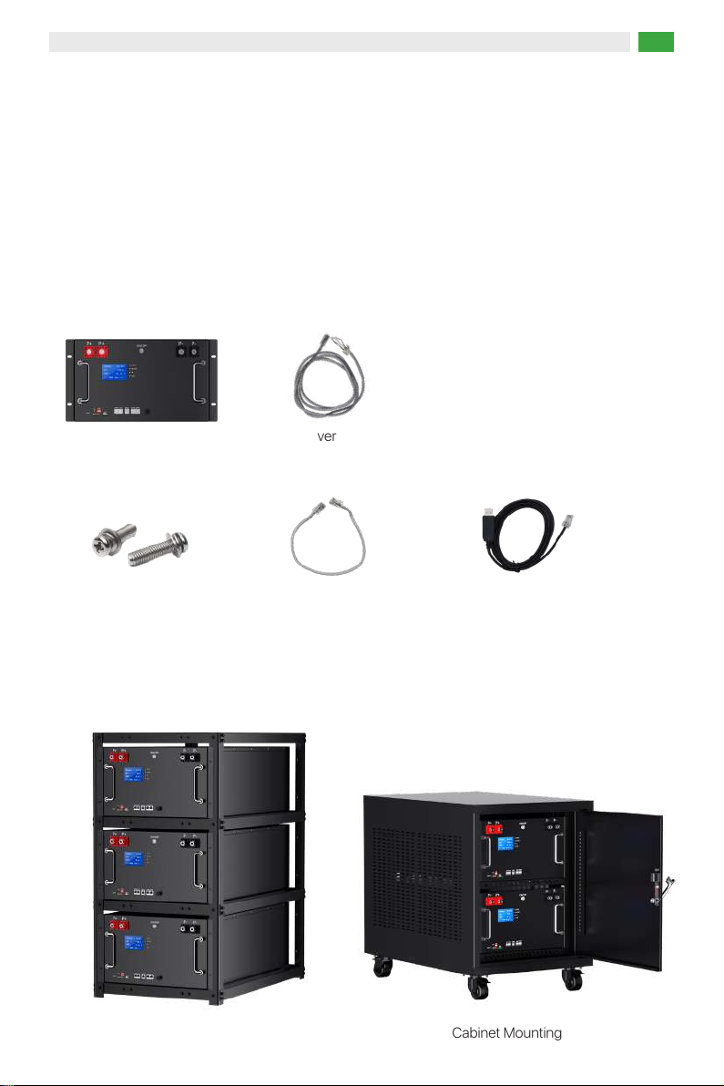
6.1 Packing
a. After receiving the battery, open the box to check the battery surface if get any broken, crack,s or
other bad phenomena; if get that, please do not install, and need to contact the supplier, and wait
for the supplier's reply before proceeding to the next step.
b. Please ensure that the following items are included in the packaging:
6.2 Installation Diagram
Battery*1
Bracket Mounting Cabinet Mounting
M8*12mm
combination screws*4
Parallel
communication cable*1
Inverte
communication cable*1
Upper system
communication cable*1
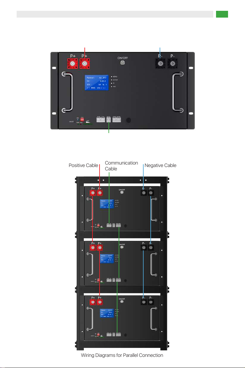
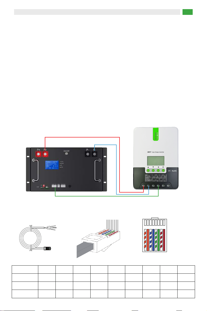
Wiring Diagrams for One Pack
Wiring Diagrams for Parallel Connection
Positive Cable
Communication
Cable
Positive Cable Negative Cable
BASENGREEN, YOUR RELIABLE POWER 08
Communication Cable to the inverter
Negative Cable
BASENGREEN, YOUR RELIABLE POWER 09
7. Connection
Communication cable connection Pin definition is as follows:
7.1 Precautions Before Connecting The Inverter
a. Use a multi-meter to measure whether connection of the positive and negative cables are
conducting, and check whether that connections are loose.
b. The battery should be switched off before wiring to ensure that there is no DC output from the
battery.
c. Connect positive terminals of the battery and the inverter with red power cable, and then connect
positive terminals of both sides with black power cable.
d. Connect both communication ports of the battery(RS485A/CAN) and the inverter(BMS port) with
the communication cable, BMS ports of inverter have different definitions for some brands, please
check the inverter manual.
1 2 3 4 5 6 7 8
RJ45 plug
1 2 3 4 5 6 7 8
1 2 3 4 5 6 7 8
RS485A Port PIN
Define
1
RS485-B
2
RS485-A
3
GND
4
NC
5
NC
6
GND
7
RS485-A
CAN Port PIN
Define
1
NC
2
NC
3
NC
4
CAN-L
5
CAN-H
6
NC
7
GND
8
RS485-B
8
NC
Communication Cable
Battery
Positive Cable
Negative Cable
inverter

7.2 Precautions Before Connecting The Inverter with The Battery Pack in Parallel
a. Use a multi-meter to measure whether connection of the positive and negative cables are conduct-
ing, and check whether that connections are loose.
b. The battery should be switched off before wiring to ensure that there is no DC output from the
battery.
c. Lock the parallel cable wires to the positive terminal of the battery pack first, then connect another
end to the negative terminal.
d. Parallel communication cable to the RS485 port of the battery pack.
e. Connect positive terminals of the battery and the inverter with red power cable, and then connect
positive terminals of both sides with black power cable.
f. Connect both communication ports of the battery(RS485A/CAN) and the inverter(BMS port) with the
communication cable, BMS ports of inverter have different definitions for some brands, please check
the inverter manual.
Communication cable connection Pin definition is as follows:
1 2 3 4 5 6 7 8
RJ45 plug
1 2 3 4 5 6 7 8
1 2 3 4 5 6 7 8
PIN
RS485
Parallel
communi-
cation
interface
definition
Define
1
RS485
-B
2
RS485
-A
3
GND
4
NC
5
NC
6
GND
7
RS485
-A
8
RS485
-B
BASENGREEN, YOUR RELIABLE POWER 10
BASENGREEN, YOUR RELIABLE POWER 11
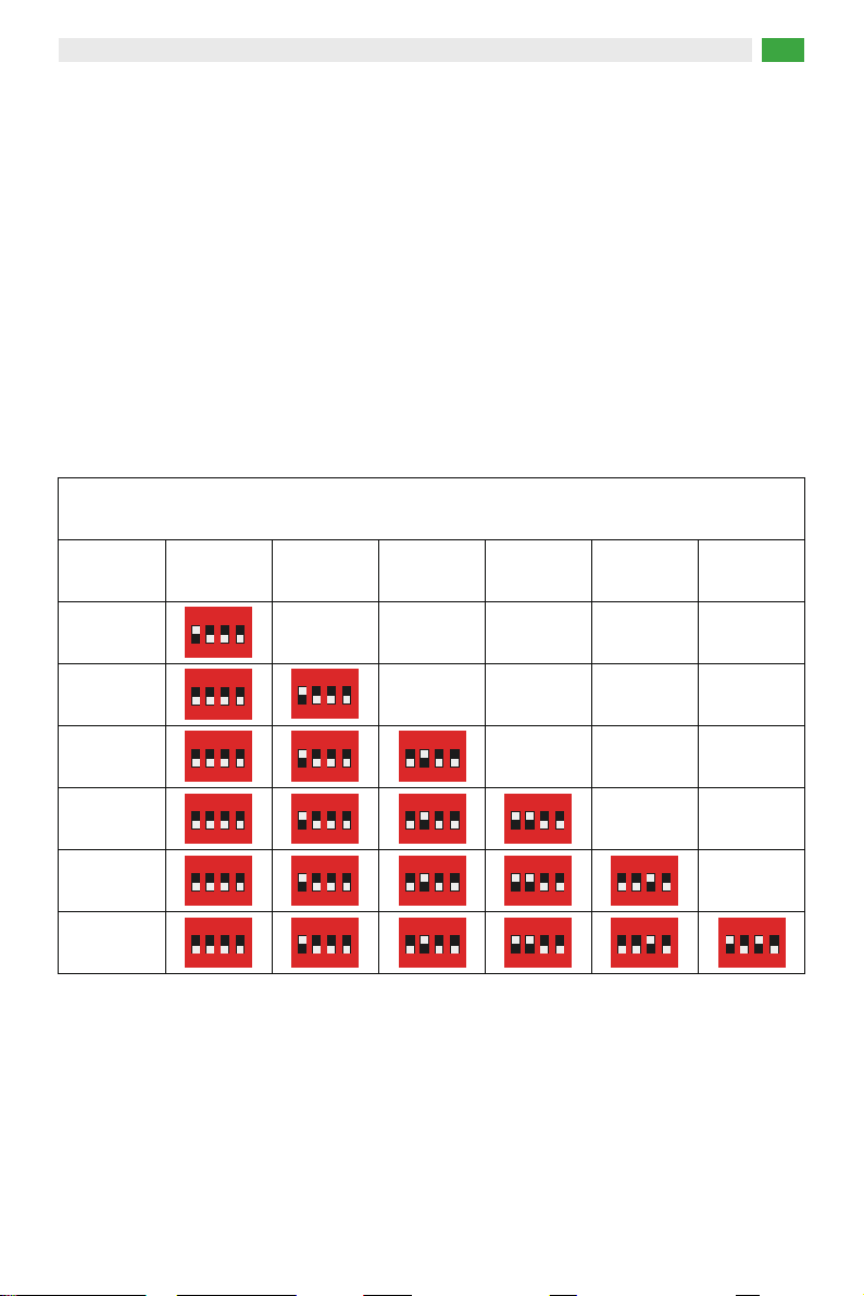
7.3 Dip Code Switch Definition and Setting
ADD switch is a 4-bit/8-bit DIP switch to manually distribute the communication address of parallel
batteries.
The BMS will only recognize the DIP address once it is reset, so please reset the BMS when the DIP
address is changed (the BMS must be reset in the standby state). When the DIP address is 0, the
battery is configured as the stand-alone working mode; when the DIP address is 1, the BMS is
configured as the master working mode; when the DIP address is 2 to 6, the BMS is configured as the
slave working mode.
Please refer to the table below to set the DIP switch for parallel connection of different batteries.
Battery pack
1
Master Slave 2 Slave 3
4-bit
Slave 4 Slave 5 Slave 6
2
3
4
5
6
ON
1 2 3 4
L
E
ON
1 2 3 4
L
E
ON
1 2 3 4
L
E
ON
1 2 3 4
L
E
ON
1 2 3 4
L
E
ON
1 2 3 4
L
E
ON
1 2 3 4
L
E
ON
1 2 3 4
L
E
ON
1 2 3 4
L
E
ON
1 2 3 4
L
E
ON
1 2 3 4
L
E
ON
1 2 3 4
L
E
ON
1 2 3 4
L
E
ON
1 2 3 4
L
E
ON
1 2 3 4
L
E
ON
1 2 3 4
L
E
ON
1 2 3 4
L
E
ON
1 2 3 4
L
E
ON
1 2 3 4
L
E
ON
1 2 3 4
L
E
ON
1 2 3 4
L
E

BASENGREEN, YOUR RELIABLE POWER 12
8. Operation
8.1 Check Before Power on
a. Check all positive, negative cables and communication lines are connected correctly and safely.
b. Check the battery is firmly installed, easy to operate and maintain, and check ventilation.
c. Insulate the unused ports.
8.2 Power on
a. Turn on the switch on the battery.
b. The green running LED is normal on(Check the status of the LED indicators)
c. If it is failed to switch on the battery system, check if all the electrical connection is correct.
d. If the electrical connection is correct, but the battery system is still unable to switch on, contact our
after-sale service within 48 hours
Battery pack
1
Master1 Slave 2 Slave 3 Slave 4 Slave 5 Slave 6
1
ON DIP
2 3 4 5 6 7 8
2
1
ON DIP
2 3 4 5 6 7 8
1
ON DIP
2 3 4 5 6 7 8
1
ON DIP
2 3 4 5 6 7 8
1
ON DIP
2 3 4 5 6 7 8
1
ON DIP
2 3 4 5 6 7 8
1
ON DIP
2 3 4 5 6 7 8
1
ON DIP
2 3 4 5 6 7 8
3
1
ON DIP
2 3 4 5 6 7 8
1
ON DIP
2 3 4 5 6 7 8
1
ON DIP
2 3 4 5 6 7 8
1
ON DIP
2 3 4 5 6 7 8
4
1
ON DIP
2 3 4 5 6 7 8
5
1
ON DIP
2 3 4 5 6 7 8
1
ON DIP
2 3 4 5 6 7 8
1
ON DIP
2 3 4 5 6 7 8
1
ON DIP
2 3 4 5 6 7 8
1
ON DIP
2 3 4 5 6 7 8
1
ON DIP
2 3 4 5 6 7 8
1
ON DIP
2 3 4 5 6 7 8
6
1
ON DIP
2 3 4 5 6 7 8
8-bit

BASENGREEN, YOUR RELIABLE POWER 13
Status Charging
L1●L2●L3●L4●
Discharge
Capacity Indicator
0~16.6%
16.6~33.2%
33.2~49.8%
49.8~66.4%
L5●L6●
L1●L2●
Light OFF OFF OFF
Light
Light
OFF OFF
Light OFF
OFF OFF
OFF
OFF OFF
Light Light
OFF OFF
Light
Light
Light Light
Light Light Light Light OFF OFF
Light Light
Light
L3●L4●L5●L6●
OFF OFF OFF OFF
OFF OFF OFF OFF
Light OFF OFF
Light Light OFF OFF
66.4~83.0% Light Light Light Light Light OFF
Light Light Light Light Light OFF
83.0~100%
Status
Capacity Indicator
0~16.6%
16.6~33.2%
33.2~49.8%
49.8~66.4%
66.4~83.0%
83.0~100%
Light Light Light Light Light Light
Light Light Light Light Light Light
OFF
Item Light OFF
Flash 1 0.25 s 3.75 s
Flash 2 0.5 s 0.5 s
Flash 3 0.5 s 1.5 s
LED Indicator Status
Flashing Definition
LED Flashing Faulty
Please turn to the next page

Status Normal/warning/
protection
RUN
●●●●● ● ● ●
Power off Sleep OFF
Stand by
Charging
Normal Flash1
Warning
ALM Battery capacity LED Specification
OFF
OFF
Flash1 OFF
Warning
Discharging
Light Flash3
Normal Flash2
Flash2
OFF
Limited charging Light OFF
Normal Light OFF
ALM OFF when
protected during
over charging
ALM OFF when
protected during
over charging
ALM OFF when
discharge over
current
Flash1
Flash1 Flash2
OFF
OFF
ALL OFF
ALL OFF
Display according
to the actual SOC
Warning
(Not including
temperature )
Over charging
protection
Flash1 OFF
Over discharge
Protection
Error refers to
hardware defection
such as BMS
voltage sampling
device,charging
MOS
damage, tempera
ture sensor
disconnection, etc.
OFF Light
Error
Invalidation
Flash1 Flash2
Over
Temperature,
Low-temperature
、Over current、
Shot Circuit、
Reverse Polarity
Protection
Over
Temperature,
Low-temperature,
Over current
protection
BASENGREEN, YOUR RELIABLE POWER 14

BASENGREEN, YOUR RELIABLE POWER 15
9. Operation of Upper System
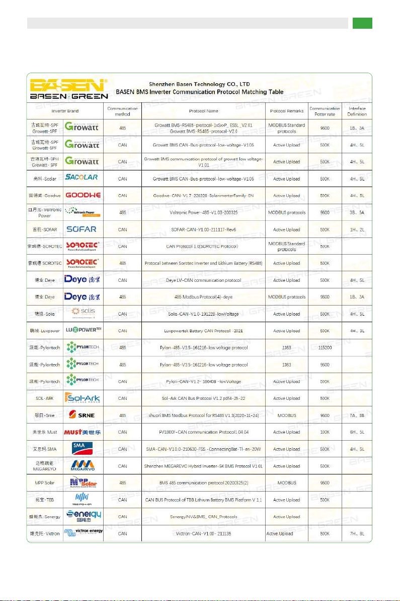
BASEN 48V battery pack supports to connect with our upper system to monitor the status of the
battery and modify the communication protocol, please contact our sales representative or visit our
website to get the latest upper system software.
9.1 Log in
a. The upper system communication cable connects to the RS485 port on the battery and then to the
USB port on the PC/Laptop
b. Download and open the upper system software
c. Modify the language
d. Updated the status of battery automatically
Notice: If it is failed to connect to the upper system, check if all the connection is correct. If the
connection is correct, but the upper system is still unable to work, please contact our after-sale service
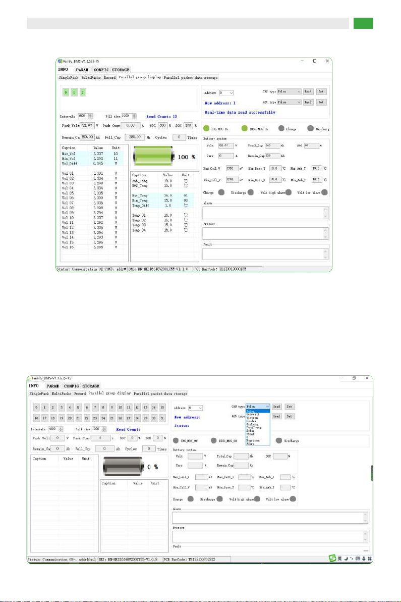
9.2 Operation of The Communication Protocol Switch
Connect to the upper system and follow the path:
INFO—Parallel Group Display—CAN Type/RS485 Type—Read—Choose the protocol—Set
BASENGREEN, YOUR RELIABLE POWER 16
BASENGREEN, YOUR RELIABLE POWER 17
9.3 Communication Compatible List

BASENGREEN, YOUR RELIABLE POWER 18
10. Storage
a. External terminals of the battery pack are insulated and protected.
b. If the battery pack is stored for a long period of time without use, it is recommended that it be
charged 30%-60%, and it is prohibited to store it completely uncharged.
c. Batteries that have been in storage for more than 3 months should be recharged for 2-3 hours at
0.2C~0.3C.
d. Batteries should be stored in a dry, clean, ventilated, non-corrosive gas environment, away from
sources of ignition, to avoid exposure to the sun.
e. Do not store or put in high temperatures over 60°C for a long period of time, otherwise, it will cause
function deterioration and life span reduction.
11. Warning
To prevent possible battery leakage, heat generation, and explosion, please observe the following
warning:
Warning!
a. It is strictly forbidden to immerse the battery in seawater or water. When not in use, it should be
placed in a cool and dry environment;
b. It is strictly forbidden to reverse the positive and negative poles to use the battery;
c. It is forbidden to use metal to directly connect the positive and negative electrodes of the battery to a
short circuit;
d. It is forbidden to transport or store batteries together with metals, such as hairpins, necklaces, etc;
e. It is forbidden to knock or throw, step on the battery, etc.;
f. It is forbidden to directly weld the battery and pierce the battery with nails or other sharp objects.
This manual suits for next models
2
Table of contents
Other BASENGREEN Batteries Pack manuals


