BASENHURT TEBAS EFka110 User manual

1
Pompa perystaltyczna / Peristaltic pump
EFka110
PL
INSTRUKCJA OBSŁUGI I INSTALACJI
EN
INSTALLATION AND MAINTENANCE INSTRUCTIONS

2
SPIS TREŚCI / TABLE OF CONTENTS
INSTRUKCJA OBSŁUGI I INSTALACJI
Lista elementów................................................................................................................ strona 4
Dane techniczne............................................................................................................................4
Zasada działania ...........................................................................................................................4
Instalacja, podłączenie hydrauliczne, podłączenie elektryczne ................................................4
Panel sterujący..............................................................................................................................6
Konfiguracja..................................................................................................................................6
Kalibracja.......................................................................................................................................8
Utrzymanie ....................................................................................................................................9
Rozwiązywanie problemów..........................................................................................................9
INSTALLATION AND MAINTENANCE INSTRUCTIONS
Packing list.........................................................................................................................page 11
Technical specifications.............................................................................................................11
Principle of operation.................................................................................................................11
Installation, Hydraulic connections, Electrical connections.................................................... 11
Control panel...............................................................................................................................13
Configuration ..............................................................................................................................13
Calibration...................................................................................................................................15
Maintenance................................................................................................................................15
Troubleshooting..........................................................................................................................16

3
OSTRZEŻENIA
Niniejsza instrukcja przeznaczona jest dla personelu technicznego odpowiedzialnego za instalację, zarządzanie i
utrzymanie urządzenia. Producent nie ponosi żadnej odpowiedzialności za uszkodzenia i usterki, które wystąpiły
po interwencji przez osoby nieuprawnione lub przez zachowania niezgodne z instrukcją.
Przed wykonaniem jakichkolwiek czynności konserwacyjnych i naprawczych, należy upewnićsię, że system jest
izolowany elektrycznie i hydraulicznie.
Z materiałem odpadowym i materiałem eksploatacyjnym należy postępowaćzgodnie z lokalnymi przepisami.
OGÓLNE WSKAZÓWKI BEZPIECZEŃSTWA
UWAGA! Przed wykonaniem jakichkolwiek operacji na pompie, należy odłączyćpompęi odprowadzićciecz
z głowicy pompy i rurek. Nigdy nie wykonuj żadnych operacji na pracującej pompie.
Podczas prac konserwacyjnych i naprawy części, które zazwyczaj sąw kontakcie z substancjami chemicznymi,
zawsze należy nosićodzieżochronną(rękawice, odzież, okulary, itp.). Pompa musi byćobsługiwana tylko przez
wykwalifikowany personel. Zawsze należy używaćoryginalnych części zamiennych.
Niezastosowanie siędo instrukcji może spowodowaćuszkodzenie sprzętu, a w skrajnych przypadkach obrażenia
ludzi.
Producent może zmodyfikowaćurządzenie, instrukcjęlub dane technicznych bez wcześniejszego
powiadomienia.
GWARANCJA
Urządzenie posiada 12-miesięcznągwarancjęod daty dostawy. Gwarancja jest nieważna, gdy instrukcje instalacji,
konserwacji i użytkowania, nie sąściśle przestrzegane przez użytkownika. Lokalne przepisy i odpowiednie normy zostały
równieżbyćprzestrzegane.
Gwarancja będzie uznana tylko wtedy, gdy spełnione zostanąnastępujące warunki:
oInstalacja, okablowanie, regulacja, konserwacja i naprawy sąwykonywane wyłącznie przez wykwalifikowany personel
oPompa dozująca była użytkowana zgodnie z jej przeznaczeniem opisanym w niniejszej instrukcji
oTylko oryginalne części zamienne były używane podczas napraw
Z gwarancji wyłączone sąwszystkie elementy eksploatacyjne (wężyki, uszczelki itp.). Uszkodzenia mechaniczne nie
podlegajągwarancji.

4
LISTA ELEMENTÓW
Pompka EFka110 jest dostarczana w komplecie z:
1) InstrukcjąObsługi
2) Uchwytem do montażu na ścianie
3) Kablem zasilającym 1.5 m
4) Standardowym zestawem: wężyk ssący z PCW, wężyk z PE, nypel ssący-filtr i zawór wtryskowy GZ½”
DANE TECHNICZNE
Przepływ/Ciśnienie 1.8 l/h / 1 bar
Wężyk ssący/wężyk głowicy 4x6 mm, PCW
Materiał Obudowa: PP
Front: Lexan – panel sterujący,
polikarbonat – przezroczyste zabezpieczenie
Uchwyt rolki: PBT
Rolki: Delrin (posiada naturalnąsmarowność)
Wewnętrzny wężyk: Santopren lub silikon
Połączenia: PP
Otoczenie Temperatura pracy maks. 45°C
Temperatura przechowywania maks. 60°C
RH maks. 90% bez kondensacji
Zabezpieczenie IP65
Wymiary 100 x 160 x 135 mm
Waga około 2 kg
Zasilanie 230 Vac, 50 Hz, jednofazowe
Pobór mocy maks. 10 VA
Zabezpieczenie elektryczne Bezpiecznik 1 A (230 V), 5x20 mm
Wyświetlacz LED, 3-cyfrowy
Wejście poziomu na odpowiednim złączu, akceptuje styk omowy z czujnikiem poziomu, 5 V/5 mA
Wejście pH/Rx na złączu BNC, impedancja wejściowa większa niż10^12 Ω,
dokładność większa niż1% FS, powtarzalność większa niż0.2% sul FS
Zakres 0.00 do 14.00 pH; 0 do +1000 mV (Redox)
ZASADA DZIAŁANIA
Zasada działania pomp perystaltycznych opiera sięo ciśnienie, a następnie zwolnienie w wężyku wewnętrznym przez rolkę
zamontowanąna uchwycie, która jest napędzana przez silnik. Podwójne działanie ciśnienia i zwolnienia wężyka wytwarza
siłęssącąwzdłużsamego wężyka, który tłoczy ciecz i napędza do przewodu wtryskowego. Natężenie przepływu zależy od
prędkości obrotowej silnika i odcinka wężyka. Polecenie jest wysyłane do silnika przez układ elektroniczny, zgodnie z
programem, aby wykryćpomiary oraz alarmy/błędy. Pompy te sąrównieżwyposażone w wbudowane narzędzie, które
wykrywa i zarządza pomiarami pH i Redoks.
INSTALACJA
Zamontuj pompęEFka110 w suchym miejscu, w maksymalnej temperaturze otoczenia 45°C, i umieść tak, aby umożliwić
łatwy dostęp dla czynności regulacyjnych i konserwacyjnych. Montażna ścianie wykonaj za pomocądołączonego uchwytu.
Przymocuj wspornik do ściany pionowej (± 15°) i podłącz pompę. Zalecane jest umieszczenie zbiornika z środkiem
chemicznym, który ma byćdozowany pod pompą, bez przekraczania maksymalnej wysokości (ok. 1,5 m). Jeśli system jest
zainstalowany poniżej poziomu środka do dozowania, okresowo sprawdzaj stan zaworu wtryskowego. W przypadku
dozowania środków, które wydzielająopary, upewnij się, że zbiornik jest zamknięty.
5
Złącze poziomu:
1 = N.C.
2 = N.C.
Podłączenie hydrauliczne
Przewód ssący
(patrz rysunek)
1. Odkręć nakrętkęmocującązłącze znajdującąsięna dole po lewej stronie głowicy
pompy, oznaczonej na rysunku strzałkąw górę.
2. Odetnij przezroczysty wężyk PCW i włóżnakrętkęmocującąna wężyk.
3. Zamontuj rurkęna stożkowym uchwycie na złączu ssącym; przesuwając, ażdo
kołnierza stopującego.
4. Zamocuj rurkę, przykręcając nakrętkęmocującądo złącza ssącego głowicy pompy.
5. Umieść rurkęw nyplu ssącym, zbiorniku lub lancy ssącej.
6. Odkręć nakrętkęmocującąnypla ssącego-filtra.
7. Odetnij przezroczysty wężyk PCW i włóżnakrętkęmocującąi docisk na rurkę.
8. Zamontuj rurkęna stożkowym uchwycie złącza filtra, przesuwając, ażdo kołnierza
stopującego.
9. Zamocuj rurkę, przykręcając nakrętkęmocującąna złączu filtra.
10. Przykręć filtr do lancy ssącej (jeśli jest używana) i/lub umieść go w jego miejscu
pracy.
Nypel ssący-filtr musi byćumieszczony w odległości minimum 5 cm od dna zbiornika.
Jeśli dozowany jest gęsty środek, zaleca się, aby usunąć filtr wewnętrzny w nyplu, w celu ułatwienia ssania.
Przewód wtryskowy
(patrz rysunek)
1. Odkręć nakrętkęmocującązłącze znajdującąsięna dole po prawej stronie głowicy pompy, oznaczonąna rysunku
ze strzałkąw dół.
2. Odetnij wężyk PCW i umieść nakrętkęmocującąna rurce.
3. Zamontuj rurkęna stożkowym uchwycie na złączu tłocznym, przesuwając, ażdo kołnierza stopującego.
4. Zamocuj rurkę, przykręcając nakrętkęmocującądo złącza głowicy pompy.
5. W miejscu wtrysku na rurociągu, zamontuj przyłącze ½ ", gwint wewnętrzny (brak w zestawie).
6. Owińgwint taśmąuszczelniającąi dokręć zawór wtryskowy do złączki.
7. Odkręć nakrętkęna złączce zaworu wtryskowego.
8. Odetnij wężyk PCW i włóżnakrętkęmocującąna przewód.
9. Zamontuj rurkęna stożkowym uchwycie na złączu zaworu wtryskowego, przesuwając, ażdo kołnierza stopującego
10. Zamocuj rurkę, przykręcając nakrętkęmocującądo złączki zaworu.
Uwaga: Zawór wtryskowy działa również, jako zawór zwrotny: nie należy go rozkręcać.
Podłączenie elektryczne
Zasilanie: 230 V~, 50/60 Hz.
Układ zasilania musi byćzabezpieczony zgodnie z odpowiednimi
przepisami prawa. Zwykle jest to wyłącznik różnicowo-prądowy 30 mA
i bezpiecznik lub bezpiecznik 1A.
Jeśli czujnik kontroli poziomu jest użyty, podłącz go do dedykowanego złącza
(patrz rysunek).
Uwaga!
Jeśli kilka pomp jest połączonych równolegle, zawsze należy przestrzegać
polaryzacji połączeńpoziomu, aby nie zagrażaćprawidłowemu
funkcjonowaniu systemu lub uszkodzeniu wejść!
Podłącz elektrodępomiarowądo złącza BNC.

6
PANEL STERUJĄCY
Wyświetlacz
podczas normalnej pracy wyświetlacz pokazuje pomiary pH i Redox (mV); następujące
komunikaty mogąsiępojawić:
-OFF pompa została wyłączona przez naciśnięcie przycisku ON/OFF
-LEU czujnik poziomu niewykryty
-PAU pompa jest „Wstrzymana” na starcie (patrz rozdział „Konfiguracja”)
-ALL „Alarm” dozowania jest aktywny (patrz rozdział „Konfiguracja”)
-UR pomiar poza zakresem, poniżej minimalnej wartości (Under-Range)
-OR pomiar poza zakresem, powyżej maksymalnej wartości (Over-Range)
przycisk ON/OFF
włącza/wyłącza system; naciśnij i przytrzymaj przez co najmniej 3 sekundy, aby wejść do trybu
KONFIGURACJI
przycisk [-]
naciśnij i przytrzymaj, aby wyświetlićwartość OFFSET elektrody (przez 3 sekundy), a następnie
wejść do trybu KALIBRACJA OFFSET
przycisk [+]
naciśnij i przytrzymaj, aby wyświetlićwartość GAIN elektrody (przez 3 sekundy), a następnie
wejść do trybu KALIBRACJA GAIN
dioda LED PULSE
czerwone światło; zapala siępodczas obrotów pompy perystaltycznej; jeśli tryb automatyczny
jest wyłączony (patrz rozdział „Konfiguracja”), dioda LED szybko miga
dioda LED ON
zielone światło; stałe świtało wskazuje normalne działanie; miga, gdy pojawi sięalarm
KONFIGURACJA
Aby skonfigurowaćpompy odpowiednio do Twoich potrzeb aplikacji, zapoznaj sięz poniższymi instrukcjami.
Parametr
Opis
Wartość
domyślna
Ustawiona
wartość
P1
Typ pomiaru:
0 = pH, dwa miejsca po przecinku
1 = pH, jedno miejsce po przecinku
2 = Redox
0
P2 Wejście poziomu:
0 = NO
1 = NC 0
P3
Przechowywanie stanu przycisku
ON/OFF przy wyłączeniu:
0 = nie
1 = tak
1
P4
Typ sterowania:
0 = OFF
1 = ON
2 = ON/OFF kwas
3 = Proporcjonalne kwas
4 = ON/OFF chlor
5 = Proporcjonalne chlor
3
P5 Próg pracy
0 do 14.0 (pH)
0 do 999 (mV) 7.00
P6 Histereza
0 do 2.00 (pH)
0 do 200 (mV) 0.40
P7 Opóźnienie uruchomienia
0 do 30 minut 0
P8 Opóźnienie alarmu
0 do 600 minut 0
Naciśnij i przytrzymaj
ON/OFF
na
co najmniej 3 sekundy.
Wyświetli się
“Edi”
przycisk [-]
przycisk [+]
Wartość
wybranego
parametru jest
wyświetlana
Zwiększenie/
zmniejszenie
numeru
parametru
Zwolnij przycisk
ON/OFF
“
Pn
” (numer
paramteru jest
wyświetlany)
ON/OFF
przycisk
[+]
przycisk
[
-
]
Zwiększenie/
zmniejszenie
wartości
parametru
ON/OFF
Zapisz ustawionąwartość i zwiększ
liczbęparametru. Na ostatnim
parametrze zamknij tryb konfiguracyjny.

7
Znaczenie parametrów
P1:
Parametr ten pozwala wybraćtyp pomiaru, pH lub Redox (mV).
Po ustawieniu P1=0 (odczyt pH z dwoma miejscami po przecinku), należy pamiętać, że te dwa miejsca po
przecinku sąwidoczne tylko dla wartości pH poniżej 10, ponieważwyświetlacz może pokazaćdo trzech
cyfr. Jednakże, na ogół dokładność pomiaru pH z jednym miejscem po przecinku jest wystarczająca w
większości zastosowań.
P2: Parametr ten pozwala na skonfigurowanie trybu pracy styku poziomu:
0 = NO (normalnie otwarty, standardowa konfiguracja)
1 = NC (normalnie zamknięty, tryb awaryjny)
P3: Ten parametr pozwala na przechowywanie stanu przycisku ON/OFF po wyłączeniu systemu:
0 = przy uruchomieniu pompa jest zawsze włączona
1 = przy uruchomieniu pompa powraca do stanu przed wyłączeniem systemu
P4: Parametr ten pozwala na ustawienie trybu pracy pompy:
0 = OFF pompa jest zawsze wyłączona, niezależnie od wartości pomiaru: ta opcja pozwala monitorować
pomiaru bez interwencji, na przykład podczas uruchomienia urządzenia
1 = ON pompa jest zawsze włączona, niezależnie od wartości pomiaru: ta opcja jest używana do
ręcznego wymuszonego dozowania, na przykład podczas uruchomienia urządzenia lub konserwacji
2 = ON/OFF kwas ta opcja jest zazwyczaj używana do zakwaszania: pompa aktywuje się, gdy pomiar
przekracza poziom „próg pracy + ½ histerezy” i dezaktywuje, gdy pomiar spada poniżej wartości „próg
pracy – ½ histerezy”
3 = Proporcjonalne kwas pompa jest całkowicie aktywna, gdy pomiar jest większy, niżwartość „próg
pracy + ½ histerezy” i całkowicie nieaktywna, gdy pomiar jest niższy, niżwartość „próg pracy – ½
histerezy”
podczas, gdy dla pomiarów między tymi ograniczeniami, czas pracy pompy jest proporcjonalny
do odległości pomiarów od wartości granicznych. Podstawa czasu stała (90 sekund) i działanie następuje
według tendencji, jako pokazano w poniższej tabeli:
Pomiar = pH ; Próg pracy = 7.20 pH ; Histereza = 0.40 pH
Pomiar <= 7.00 7.10 7.20 7.30 >= 7.40
% dozowania 0% 25% 50% 75% 100%
Pompa ON nigdy 23 sekund 45 sekund 67 sekund zawsze
Pompa OFF zawsze 67 sekund 45 sekund 23 sekund nigdy
4 = ON/OFF chlor ta opcja jest zazwyczaj używana do chlorowania lub alkalinizacji;: pompa aktywuje
się, gdy pomiar jest niższy, niżwartość „próg pracy – ½ histerezy i dezaktywuje się, gdy pomiar przekracza
„próg pracy + ½ histerezy”
5 = Proporcjonalne chlor pompa jest całkowicie aktywna, gdy pomiar jest niższy, niżwartość „próg pracy
– ½ histerezy” i całkowicie wyłączona, gdy wartość jest większa niż„próg pracy + ½ histerezy” podczas,
gdy dla pomiarów między tymi ograniczeniami, czas pracy pompy jest proporcjonalny do odległości
pomiarów od wartości granicznych. Podstawa czasu stała (90 sekund) i działanie następuje według
tendencji, jako pokazano w poniższej tabeli:
Pomiar = Redox ; Próg pra
cy = 680 mV ; Histereza = 20 mV
Pomiar <= 670 675 680 685 >= 690
% dozowania 100% 75% 50% 25% 0%
Pompa ON zawsze 67 sekund 45 sekund 23 sekund nigdy
Pompa OFF nigdy 23 sekund 45 sekund 67 sekund zawsze
P5: Ten parametr pozwala ustawićpróg pracy używany, gdy pompa działania w trybie automatycznego
sterowania
P6: Ten parametr przedstawia interwencjęhisterezy wokół progu pracy; w przypadku ON/OFF sterowanie może
byćustawione od zera do 2,00 pH (lub pomiędzy zerem a 200 mV), podczas, gdy w przypadku
proporcjonalnego sterowania histereza musi miećwartość między 0,20 a 1,00 pH (lub między 20 i 100 mV).
P7: Przy uruchomieniu urządzenia, niektóre elektrody wymagajączasu na stabilizację(lub polaryzację), w
którym pomiar nie jest wiarygodny. Parametr ten pozwala na ustawienie opóźnienia przy uruchomieniu
(w minutach), w którym pompa jest wyłączona, a na wyświetlaczu pokazuje siępomiar i komunikat "PAU".
Zazwyczaj w przypadku elektrody pH opóźnienie 1 minuty jest wystarczające, podczas gdy w przypadku
elektrody Redox zalecane jest ustawienie czasu opóźnienia na co najmniej 20 minut. Czasami czas
oczekiwania jest równieżprzydatny w celu skompensowania opóźnienia hydraulicznego, które może wystąpić
przy uruchomieniu instalacji. Po upływie ustawionego czasu, pompa zaczyna pracowaćnormalnie.

8
P8: Ten parametr pozwala określićtermin, w którym środek musi powrócićdo wartości progowej pracy (P5), w
przeciwnym razie zostanie wygenerowany alarm. Czas może byćustawiony pomiędzy 0 (funkcja
wyłączona) i 600 minut (10 godzin). Odliczanie alarmu rozpoczyna się, gdy system wykryje pomiar poza
zakresem i automatycznie zresetuje, gdy pomiar powróci do odpowiednich wartości. Jeśli pomiar pozostaje
poza zakresem dłużej, niżustawiony czas, alarm jest generowany, a wyświetlacz pokazuje naprzemiennie
pomiar i komunikat „ALL”. Gdy alarm jest aktywny, dozowanie jest wyłączone i normalna praca zostanie
wznowiona, gdy alarm zostanie zresetowany poprzez naciśnięcie przycisku ON/OFF, wyłączenie i
włączenie pompki lub automatycznie, gdy pomiar wróci do prawidłowej wartości. Taka sytuacja może
wystąpićze względu na niewystarczające dozowanie niepozwalające na osiągnięcie wartości progowej.
KALIBRACJA
Kalibracja pH
1. Przepłucz elektrodęw wodzie destylowanej, a następnie zanurz w buforze pH 7.01.
2. Poczekaj klika sekund, ażsystem sięustabilizuje.
3. Naciśnij i przytrzymaj przycisk [-], dopóki nie pojawi siękomunikat “OFS” (kalibracja OFFSET).
4. Naciśnij ON/OFF, aby potwierdzićkalibracjęlub poczekaj kilka sekund na zamknięcie bez zapisywania i zachowania
poprzedniej kalibracji.
5. Przepłucz elektrodęw wodzie destylowanej, a następnie zanurz w roztworze pH 4.01 (lub 9.01).
6. Poczekaj klika sekund, ażsystem sięustabilizuje.
7. Naciśnij i przytrzymaj przycisk [+], dopóki nie pojawi siękomunikat “GAI” (kalibracja GAIN).
8. Naciśnij ON/OFF, aby potwierdzićkalibracjęlub poczekaj kilka sekund na zamknięcie bez zapisywania i zachowania
poprzedniej kalibracji.
Uwagi
-Jeśli próbujesz wykonaćkalibracjęOFFSET, a wartość pH jest daleko od 7.00 lub kalibracjęGAIN ze zbyt neutralnym
roztworem pH, procedura nie powiedzie się, a na wyświetlaczu pojawi siękomunikat "Err".
-W trakcie normalnej pracy, możliwe jest, aby wyświetlićwartości OFFSET (naciskając [-]) i wartości GAIN (naciskając
[+]), aby sprawdzićstan elektrody. Idealne wartości dla OFFSET musząbyćbliskie zeru a dla GAIN bliskie 1.000. Gdy
te wartości sąbliskie maks./min. granicom (OFFSET: -1.00 pH…. +1.00 pH; GAIN 0.750…1.500), elektroda jest
zanieczyszczona lub zużyta.
Kalibracja Redox
1. Przepłucz elektrodęw wodzie destylowanej, a następnie zanurz w roztworze kalibracyjnym (np. 220 mV).
2. Poczekaj klika sekund, ażsystem sięustabilizuje.
3. Naciśnij i przytrzymaj przycisk [-], dopóki nie pojawi siękomunikat “OFS” (kalibracja OFFSET).
4. Naciśnij ON/OFF, aby potwierdzićkalibracjęlub poczekaj kilka sekund na zamknięcie bez zapisywania i zachowania
poprzedniej kalibracji.
Uwagi
-Kalibracja Redox jest procedurąjednopunktową(OFFSET). Jednakże, naciskając przycisk [+] powoduje, że system
wchodzi do kalibracji GAIN, ale bez żadnego wpływu.
-W trakcie normalnej pracy, możliwe jest, aby wyświetlićwartości OFFSET (naciskając [-]), aby sprawdzićstan
elektrody. Idealna wartość dla OFFSET musi byćbliska zeru. Gdy ta wartość jest bliska maks./min. granicom
(-100 mV…+100 mV), elektroda jest zanieczyszczona lub zużyta.
UTRZYMANIE
Okresowe czynności konserwacyjne sąniezbędne do prawidłowego funkcjonowania systemu i czas jego żywotności.
Poniższe porady powinny byćściśle przestrzegane.
Przed wykonaniem jakichkolwiek prac upewnij się, że urządzenie jest odłączone!
Tygodniowe prace:
-Sprawdźpoziom środka do dozowania, aby zapobiec pracy pompy na sucho
-Sprawdź, czy przewody ssące i głowica sączyste i nie zawierajążadnych zanieczyszczeń
-Sprawdź, czy nypel ssący-filtr nie jest zatkany, aby uniknąć zmniejszenia przepływu
Prace co trzy miesiące:
-Oczyść wszystkie części, które mająkontakt z substancjąchemiczną(korpusu pompy, podstawęfiltra i zaworu
wtryskowy). Jeśli pompa dozuje dodatki, które tworząkryształy, czyszczenie należy wykonaćczęściej.

9
Postępuj w następujący sposób:
oZanurz przewód ssący i nypel ssący-filtr w czystej wodzie. Uruchom pompęi pozostaw pracującąna kilka minut,
aby umożliwićwodzie umycie głowicy pompy.
Jeśli występująkryształy, które należy usunąć, postępuj w następujący sposób:
oPo pierwsze zastosuj odpowiedni środek chemiczny (zamiast wody) w celu rozpuszczenia kryształów (na przykład
kwas solny dla kryształów podchlorynu sodu) i pozwól na pracępompy na kilka minut.
oPowtórz procedurę, używając czystej wody.
Gdy czyszczenie zostało wykonywane, podłącz ponownie pompkędo urządzenia i wznów normalne działanie.
Dodatkowa konserwacja – Wymiana bezpiecznika
Ta operacja musi byćwykonana tylko przez wykwalifikowany personel. Jeśli nie jest to możliwe, należy wysłać
urządzenie do dostawcy lub producenta.
-Zdejmij pompęz uchwytu
-Odkręć 6 śrub obudowy i otwórz tylni panel
-Wymieńbezpiecznik i wystaw nowy tego samego typu (wielkość i rozmiar)
-Jeśli jednak bezpiecznik przepali sięponownie, należy wysłaćurządzenie do serwisu/dostawcy
-Zamknij tylni panel
Dodatkowa konserwacja – Wymiana wężyków perystaltycznych:
Odkręć dwie przednie śruby i zdejmij przezroczystąosłonę. Aby usunąć stary wężyk,
najpierw zwolnij lewe złącze, a następnie obróćuchwyt tak, jak pokazano na rysunku.
Ustaw pompęna ciągłąpracę(P4=1), ale zatrzymaj jąprzyciskiem ON/OFF.
Włóżlewe złącze do nowego wężyka, do jego obudowy, upewniając się, że zaokrąglona
część jest umieszczona wewnątrz. Następnie obróćuchwyt zgodnie z ruchem
wskazówek zegara tak, żeby umieścićwężyk w jego obudowie.
Włóżprawe złącze w jego obudowęi dokręć dwie przednie śruby, aby przymocować
przezroczystąosłonę. Podłącz przewód ssący i wtryskowy, a następnie ustaw
prawidłowo parametr P4.
Przezimowanie pompki:
Przed wyłączeniem systemu na przezimowanie, a także podczas dłuższego czasu nieużytkowania
urządzenia, dozuj czystąwodę, aby przepłukaćrurki, a następnie obróćw prawo uchwyt, aby
ustawićgo w sposób, jak pokazano na rysunku.
ROZWIĄZYWANIE PROBLEMÓW
1. Jeśli pompa nie włącza się:
-Sprawdźpodłączenie zasilania
2. Jeśli pompa włącza się, ale nie pracuje:
-Sprawdź, wyświetlacz i konfigurację: pompa może byćodłączona lub alarm jest aktywny
3. Pompa pracuje prawidłowo, ale nie wtryskuje środka do urządzenia:
-Sprawdźpoziom środka w zbiorniku
-Sprawdź, czy nypel ssący-filtr nie jest zatkany
-Sprawdź, czy zawór wtryskowy nie jest zatkany
-Sprawdźzawór ssący i tłoczny
4. Wyciek cieczy z pompy:
-Sprawdź, czy rurki sądobrze włożone, a nakrętki dokręcone
-Sprawdź, czy ciśnienie w punkcie wtrysku nie jest za wysokie
-Zdejmij przezroczystąpokrywęi sprawdźrurkęwewnętrzną

10
WARNINGS
This manual is dedicated to the technical personnel responsible of the installation, management and maintenance of the
plants. The manufacturer assumes no responsibility for damages or malfunctions occurring after intervention by non-authorized
personnel, or not compliant with the prescribed instructions.
Before performing any maintenance or repair action, ensure that the system is electrically and hydraulically insulated.
Dispose of waste material and consumables accordingly with local regulations.
GENERAL SAFETY TIPS
WARNING! Before performing any operation on the pump, unplug the pump and discharge the liquid from the
pump head and tubes. Never operate on working pump.
During maintenance and repair of parts that normally become in contact with chemicals, The pump has to
be handled by qualified personnel only. Always use original spare parts for maintenance.
Failure to follow instructions can cause damage to the equipment and, in extreme cases, to people.
Warranty
The EFka110 is warranted for a period of 12 months from the delivery date.
Warranty is not valid if all instructions of installation, maintenance and use, are not strictly followed by the user.
Local regulations and applicable standards have also to be followed.
In particular, the warranty will be recognized only if the following conditions are fulfilled:
oThe installation, wiring, adjustment, maintenance and repairs performed only by qualified personnel
oThe dosing pump was used according to instructions provided in this manual
oOnly original spare parts have been used for repairs
The manufacturer can modify the instrument or the technical manual without advanced notice.
From the guarantee are excluded all consumables (tubing, seals, etc.). Mechanical damage is not covered under warranty.

11
PACKING LIST
The EFka110 pump is supplied complete with:
-Bracket for wall installation
-Standard kit including suction and head tube, foot filter and injection valve
-Power cable, 1.5 m (internally pre-wired)
-Instruction manual
TECHNICAL SPECIFICATIONS
Flow rate / Pressure 1.8 l/h / 1 bar
Suction / head tube 4x6 mm, PVC Crystal
Materials Case: PP
Front: Lexan control panel,
polycarbonate transparent protection
Roller-holder: PBT
Rollers: Delrin (self-lubricant)
Internal tube: Santoprene or silicone
Connections: PP
Environment Working temperature max. 45°C
Storage temperature max. 60°C
RH max. 90% noncondensing
Protection rate IP65
Dimensions 100 x 160 x 135 mm
Weight approx. 2 kg
Power supply 230 Vac, 50 Hz, single phase
Power consumption max 10 VA
Electrical protection Fuse 1 A (@ 230 V), 5x20 mm
Display LED, 3 digit
Level input on proper connector, accept ohmic contact from level sensor, 5 V / 5 mA
pH/RX input on BNC connector, input impedance greater than 10^12 Ω,
precision better than 1% FS, repeatability better than 0.2% sul FS
Measure ranges 0.00 to 14.00 pH; 0 to +1000 mV (redox)
PRINCIPLE OF OPERATIONS
The principle of operation of the peristaltic pumps is based on the pressure and subsequent release of the internal tube by
the roller mounted on the roller-holder, which is driven by the motor. The dual action of pressure and release of the tube
generates a suction force along the tube itself which primes the liquid and guide it to the injection line.
The command is sent to the motor by the electronic unit according to the program, to the detected measurement and to the
absence of alarms/errors. These pumps are also equipped with a built-in instrument, that detects and manages pH and
redox measurements.
INSTALLATION
Install the EFka110 pump in a dry area, at a maximum ambient temperature of 45°C, and place it such as to allow easy
adjustment and maintenance operations. Wall mount the pump using the supplied bracket. Secure the bracket to a vertical
wall (±15°) and attach the pump. It is recommended to place the tank of the product to be dosed below the pump, without
exceeding the maximum suction height (approx. 1.5 m). If the system is installed below the level of the liquid, periodically
check the status of the injection valve. If dosing a liquid that gives off fumes, make sure the tank is sealed.

12
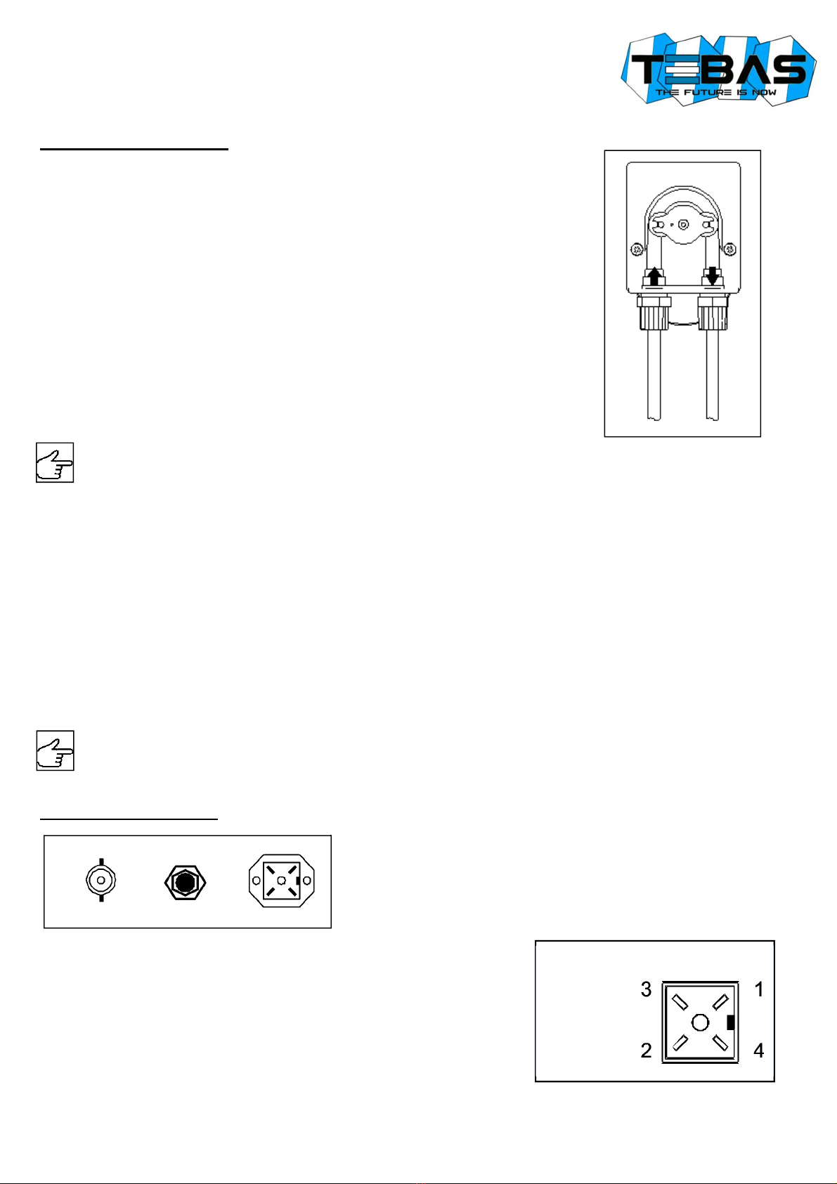
Level Connector:
1 = N.C.
2 = N.C.
Hydraulic connections
Suction line
(also see drawing)
1. Unscrew the fixing nut of the suction fitting located at the bottom left of the pump body,
marked with the entering arrow.
2. Cut the PVC Crystal tube and insert the tube fixing nut onto the tube.
3. Mount the tube on the conic hose of the suction fitting, pushing it to reach the stop
collar.
4. Secure the tube by screwing the tube fixing nut on the suction fitting of the pump body.
5. Place the tube inside the tank and/or the suction lance.
6. Unscrew the tube fixing nut of the foot filter fitting.
7. Cut the PVC Crystal tube and insert the tube fixing nut onto the tube.
8. Mount the tube on the conic hose of the foot filter, pushing it to reach the stop collar.
9. Secure the tube by screwing the tube fixing nut on the foot filter fitting.
10. Screw the foot filter on the suction lance and/or place it in its working site.
Place the foot filter at a minimum distance of 5 cm from the tank bottom.
If a dense product is dosed, it is advisable to remove the internal filter, in order to
facilitate the aspiration.
Injection line
(also see drawing)
1. Unscrew the fixing nut of the injection fitting located at the bottom left of the pump body,
marked with the exiting arrow.
2. Cut the PVC Crystal tube and insert the tube fixing nut onto the tube.
3. Mount the tube on the conic hose of the injection fitting, pushing it to reach the stop collar.
4. Secure the tube by screwing the tube fixing nut on the injection fitting of the pump body.
5. Apply at the injection point of the pipeline a ½” GAS fitting, internally threaded (not supplied).
6. Garnish the thread with PTFE tape and screw the injection valve on the fitting.
7. Unscrew the tube fixing nut of the injection valve fitting.
8. Cut the PVC Crystal tube and insert the tube fixing nut onto the tube.
9. Mount the tube on the conic hose of the injection valve, pushing it to reach the stop collar.
10. Secure the tube by screwing the tube fixing nut on the valve fitting.
The injection valve also works as non-return valve. Never disassemble it internally.
Electrical connections
Power supply: 230 V~, 50/60 Hz.
The mains circuit must be protected in accordance with the relevant laws
and regulations. Typically, the protection is given by a 30 mA differential
switch and a breaker or 1 A fuse.
If a level control sensor is used, plug it to its connector (see figure).
Warning! If several pumps are connected in parallel, always observe the
polarity of the level connection, not to endanger the proper functioning of the
system or damage the inputs!
Connect the measurement electrode to the BNC connector.

13
CONTROL PANEL
Display
during normal operations displays the measured pH or redox (mV); the following messages may
also appear:
-OFF the pump has been disabled by pressing the ON/OFF button
-LEU the level sensor consent is missing
-PAU the pump is “Paused” at start-up (also see “Configuration” section)
-ALL a dosage “Alarm” is active (also see “Configuration” section)
-UR measurement out of range, below the minimum value (Under-Range)
-OR measurement out of range, above the maximum value (Over-Range)
ON/OFF key
enables/disables the system; press and hold for at least 3 seconds to enter the CONFIGURATION
mode
[-] key
press and hold to display the electrode offset value (for 3 seconds) and then enter the OFFSET
CALIBRATION mode
[+] key
press and hold to display the electrode gain value (for 3 seconds) and then enter the GAIN
CALIBRATION mode
PULSE LED
red light; lights up during rotation of the peristaltic pump; if the automatic mode is disabled (see
“Configuration” section), the LED flashes quickly
ON LED
green light; fixed ON indicates normal operations; flashes when an alrm occurs
CONFIGURATION
To configurate the pump accordingly with your application needs, refer to the below instructions.
Parameter
Description Default
value Set
value
P1 Measure type:
0 = pH with two decimal
1 = pH with one decimal
2 = Redox
0
P2 Level input:
0 = NO
1 = NC
0
P3 Storage of the ON/OFF key status at shutdown:
0 = no
1 = yes
1
P4
Control type:
0 = OFF
1 = ON
2 = ON/OFF acid
3 = Proportional acid
4 = ON/OFF chlorine
5 = Proportional chlorine
3
P5 Working threshold
0 to 14.0 (pH)
0 to 999 (mV)
7.00
P6 Hysteresis
0 to 2.00 (pH)
0 to 200 (mV)
0.40
P7 Delay at start-up
0 to 30 minutes 0
P8 Alarm delay
0 to 600 minutes 0
Press and hold the
ON/OFF key for at least
3 seconds
“
Edi
” is
displayed
[-] key
[+] key
The value of
the selected
parameter is
displ
a
yed
Increase /
decrease the
parameter
number
Release the
ON/OFF key
“
Pn
” (no. of
parameter)
is
displayed
ON/OFF
[+]
key
[
-
]
key
Increase /
decrease the
parameter value
ON/OFF
Store the set value and
increase the parameter
number.

14
Meaning of parameters
P1: This parameter allows to select the measurement type, pH or redox (mV).
When setting P1=0 (pH reading with two decimal), please note that the two decimal places are visible only
for pH values below 10, because the display can show up to three digits. However, generally the precision of
pH measurements with one decimal is sufficient in most applications.
P2: This parameter allows to configure the working mode of level contact:
0 = NO (normally open, standard configuration)
1 = NC (normally closed, fail-safe mode)
P3: This parameter allows to store the status of the ON/OFF button at the system shutdown:
0 = at start-up the pump is always enabled
1 = at start-up the pump restores its status at shutdown
P4: This parameter allows to set the pump working mode:
0 = OFF the pump is always off, independently from measured value: this option allows to monitor the
measurement without intervening, for example during the plant start-up
1 = ON the pump is always on, independently from measured value: this option is used to manually force
the dosage, for example during the plant start-up or maintenance
2 = ON/OFF acid this option is typically used for acidification; the pump activates when the measurement
exceeds the “working threshold +½ hysteresis” level, and deactivates when the measurement falls below the
“working threshold – ½ hysteresis” value
3 = Proportional acid the pump is definitely active when the measurement is greater than the “working
threshold + ½ hysteresis” level, and definitely off when measurement is lower than the “working threshold
– ½ hysteresis” value, while for measurements between these limits, the operating time of the pump is
proportional to the distance of measurement from the limits. The time base is fixed (90 seconds) and
operation follows the trend shown in the table below:
Measurement = pH ; Working threshold = 7.20 pH ; Hysteresis = 0.40 pH
Measure <= 7.00 7.10 7.20 7.30 >= 7.40
% dosage 0% 25% 50% 75% 100%
Pump ON never 23 seconds 45 seconds 67 seconds always
Pump OFF always 67 seconds 45 seconds 23 seconds never
4 = ON/OFF chlorine this option is typically used for chloration or alkalinization; the pump activates when
the measurement is lower than the “working threshold – ½ hysteresis” value, and deactivates when the
measurement exceeds the “working threshold + ½ hysteresis” level.
5 = Proportional chlorine the pump is definitely active when the measurement is lower than the “working
threshold – ½ hysteresis” value, and definitely off when measurement is greater than the “working threshold
+ ½ hysteresis” level, while for measurements between these limits, the operating time of the pump is
proportional to the distance of measurement from the limits. The time base is fixed (90 seconds) and
operation follows the trend shown in the table below:
Measurement = Redox ; Working threshold = 680 mV ; Hysteresis = 20 mV
Measure <= 670 675 680 685 >= 690
% dosage 100% 75% 50% 25% 0%
Pump ON always 67 seconds 45 seconds 23 seconds never
Pump OFF never 23 seconds 45 seconds 67 seconds always
P5: This parameter allows to set the working threshold used when the pump operates in automatic control.
P6: This parameter represents the intervention hysteresis around the working threshold; in the case of ON/OFF
controls it can be set between zero and 2.00 pH (or between zero and 200 mV), while in the case of
proportional controls the hysteresis must have a value between 0.20 and 1.00 pH(or between 20 and 100mV).
P7: At the device start-up, some electrodes require a stabilization (or polarization) time, during which the
measurement is not reliable. This parameter allows to set a delay at start-up (in minutes), during which the
pump is off and the display alternates between the measurement and the “PAU” message. Typically, in the
case of pH electrode a delay of 1 minute is sufficient, while in the case of redox electrode it is recommended
to set a delay of at least 20 min. Sometime this standby time is also useful to compensate for hydraulic delays
that can occur at the plant start-up. Once the set time has elapsed, the pump begins to operate normally.
P8: This parameter allows to set a time limit within which the measure must return to the working threshold value
(P5), otherwise an alarm is generated. A time between 0 (feature disabled) and 600 min. (10 hours) can be
set. The alarm time count begins when the system detects a measurement out of range, and automatically
resets when the measure returns within the threshold value. If the measurement remains outside this
threshold longer than the set time, an alarm is generated and the display alternates between the measurement
and the “ALL” message. When the alarm is active, the dosage is disabled and normal operation is resumed
when the alarm is reset by pressing the ON/OFF button, by turning the pump off and on again, or
automatically when measurement returns to an acceptable value. This condition may occur due to an
insufficient dosage, such as not to allow the achievement of the threshold value.

15
CALIBRATION
pH calibration
1. Rinse the pH electrode with distilled water, then immerse it in the pH 7.01 buffer solution
2. Wait a few seconds for the system stabilization
3. Press and hold the [-] key until the message “OFS” (OFFSET calibration) is displayed
4. Press ON/OFF to confirm the calibration or wait for a few seconds for exiting without saving and keeping the previous
calibration
5. Rinse the electrode with distilled water, then immerse it in the pH 4.01 (or 9.01) buffer solution
6. Wait a few seconds for the system stabilization
7. Press and hold the [+]key until the message “GAI” (GAIN calibration) is displayed
8. Press ON/OFF to confirm the calibration or wait for a few seconds for exiting without saving and keeping the previous
calibration
Notes
-If trying to perform an OFFSET calibration at a pH value very far from 7.00 or a GAIN calibration with a buffer
solution of pH too close to neutrality, the procedure is not successful and the display shows the “Err” message.
-During normal operation you can see the offset (by pressing [-]) and gain (by pressing [+]) values, to check the status
of the electrode. The ideal values are an offset close to zero and a gain close to 1.000. When these values are close
to the max / min limits (offset: -1.00pH ... +1.00pH; gain: 0.750 ... 1.500), it means that the electrode is contaminated
or dead.
Redox calibration
1. Rinse the redox electrode with distilled water, then immerse it in the calibration solution (220 mV)
2. Wait a few seconds for the system stabilization
3. Press and hold the [-] key until the message “OFS” (OFFSET calibration) is displayed
4. Press ON/OFF to confirm the calibration or wait for a few seconds for exiting without saving and keeping the previous
calibration
Notes
-The redox calibration is a single point procedure (offset). However, pressing the [+] key the system enters the GAIN
calibration, but this will not have any effect.
-During normal operation you can see the offset value (by pressing [-]),to check the status of the electrode. The ideal
value is an offset close to zero. When this value is too close to the max / min limits (-100mV ... +100mV), it means
that the electrode is contaminated or dead.
MAINTENANCE
Regular maintenance is essential if the pump has to give good service over a long period. The following advice should be
strictly followed.
Before any operation, make sure the system is unplugged!
Weekly operations:
-Check the level of the liquid to be dosed to avoid the pump working dry
-Check that in the suction and injection pipes there are no impurities
-Check the filter clogging, which may cause the decrease of flow rate
Operations every three months::
-Cleaning: clean all parts that are in contact with the dosed chemical (pump body, foot filter and injection valve). If using
additives that form crystals, clean more frequently.
Proceed as follows:
oImmerse the suction tube and foot filter into a tank containing clean water
oStart the pump for a few minutes to let the water pass through the pump body
If there are crystals to be removed, proceed as follows:
oReplace the water with an adequate chemical (e.g. hydrochloric acid for sodium hypochlorite crystals) and let
the pump work for a few minutes
oRepeat the operation with clean water
Once completed the cleaning, the pump can be connected again to the plant and start to work.

16
Extraordinary maintenance – Replacing the fuse:
This operation must be performed only by qualified personnel. If the intervention of a technician is not possible,
send the pump to the manufacturer for proper maintenance.
-Remove the pump from the mounting bracket
-Unscrew the 6 screws holding the case and open the back panel
-Replace the blown fuse on the circuit with a new one of the same type (size and dimensions)
-If the fuse blows again, send the pump to the manufacturer for repair
-Close the back panel
Extraordinary maintenance – Replacing the peristaltic tube:
Unscrew the nuts and remove the suction and injection hoses, then remove the
transparent cover by unscrewing the two front screws.
Remove the old tube first unlocking the left fitting and turning the roller-holder as
indicated by the arrow in the figure, in order to release the tube to the fitting at the right.
Set the pump for continuous operation (P4 = 1), but stop it with the ON/OFF key.
Insert the left fitting onto the new tube, in its place, while paying attention that the
rounded part is positioned inwards.
Then turn the roller-holder clockwise, so that the tube is inserted in its seat.
Insert the right fitting in its seat and secure the transparent cover by screwing the two
front screws.
Connect the suction and injection tubes, then set correctly the parameter P4.
Pump wintering:
Before turning off the system at the end of the season or for a long period, dose clean water to rinse the
tube, then place the roller-holder as shown in the figure, rotating it clockwise.
TROUBLESHOOTING
1. The pump does not turn on:
-Check the power supply connection
2. The pump turns on but does not function:
-Check display and configuration: the pump could be disabled or an alarm is active
3. The pump works correctly but does not inject liquid into the plant:
-Check the level of product in the tank
-Check that the foot filter is not clogged
-Check that the injection valve is not clogged
-Check the suction and head valves
4. Liquid leakages from pump body:
-Check that the tubes are well inserted and the nuts well tightened
-Check that the pressure at the injection point is not too high
-Remove the transparent protection cover and check the integrity of the internal tube
Table of contents
Languages:
Other BASENHURT Water Pump manuals


