SIA SIA-24-L25-CR-TSB-6050-DC-S-PS User manual

MANUAL
INSTALLATION, OPERATION & MAINTENANCE
SiA CHEMICAL INJECTION PUMP
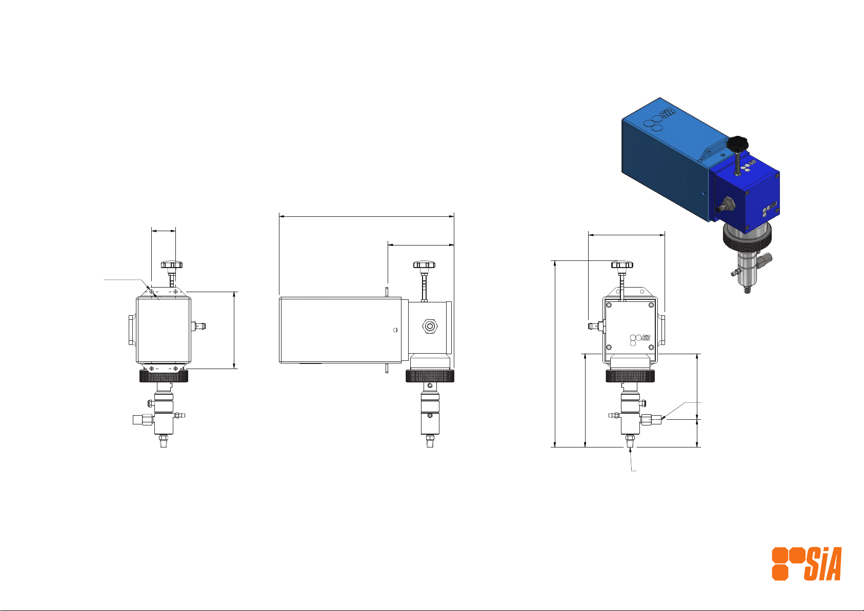
ILLUSTRATION & PARTS LIST SIA-24-L25-CR-TSB-6050-DC-S-PS
www.solarinjection.com.au
A
123 4 5 6
6
5
4321
B
C
D
E
F F
E
D
C
B
A
NO MANUAL REVISIONS ALLOWED
A3
592 Tarragindi Road,
Salisbury, Qld 4107 Tel: +61 7 3277 8822
SCALE STATUS
SIZE
SHEET OF
DWG NO. REV
TITLE
NOTES
FILE NAME
THIS DRAWING CONTAINS
CONFIDENTIAL INFORMATION
AND IS COVERED BY COPRIGHT
LAWS. REPRODUCTION EITHER
PARTIAL OR COMPLETE IS
PROHIBITED, UNLESS PRIOR
CONSENT HAS BEEN GIVEN IN
WRITING BY SOLAR INJECTION
AUSTRALIA PTY LTD
SIA-24-L25-CR-TSB-6050-DC-S-PS.idw
1
SIA-24-L25-CR-TSB-6050-DC-S-PS
GENERAL ARRANGEMENT
SIIA-24-L25-CR-TSB-6050-DC-S-PS10
F.P.
A.S.
04/09/2021
1:5
DRAWN TO AS1100-1992
UNLESS NOTED OTHERWISE:
- ALL DIMENSIONS IN mm (in)
- TOLERANCES:
MACHINING ±0.1 mm
WELDING ±1.0 mm
ANGULAR ±0.5°
DRAWN
CHECKED
DATE
5
TOTAL MASS
15.2 kg
MATERIAL
10 REVISIED FOR VAULT 7/09/2021 A.S.
REV DESCRIPTION DATE APP'D
159 APPROX
388APPROX
364
IN 1/4" NPT
OUT 1/4" NPT
160
50
8 TYP
137.5
137
195
58
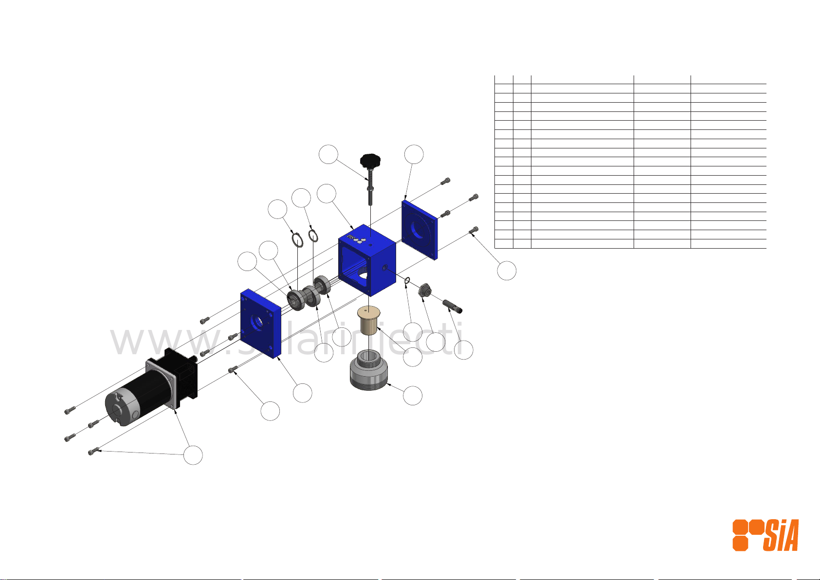
ILLUSTRATION & PARTS LIST
www.solarinjection.com.au
www.solarinjection.com.au
SIA-24-L25-CR-TSB-6050-DC-S-PS
MaterialPart NumberDescriptionQTYItem
Aluminum 606140042-1DRIVE CASE11
Aluminum-606140044-1
MOTOR END PLATE
12
Aluminum 606140047BEARING END PLATE13
431 SS40045-15-SSCRANK SHAFT 15 mm14
40023Bearing15
40024
Bearing
16
30032Bearing1
7
Steel, Mild40029Circlip18
Steel, Mild
40033
Circlip
19
Aluminum-606140046-WPump Adaptor - W Series110
Ertalyte TX40043PLUNGER ADAPTOR UPPER111
Zinc Plated40011-16
Cylinder Head Cap Screw
412
40084STROKE LENGTH ASSEMBLY113
316 SS40220SENSOR HOUSING114
Viton40067-014ORING VITON115
Stainless Steel30103SENSOR116
40069-24-6050GEARBOX 50:1, 24 VDC 60w MOTOR117
Steel, Mild40011-10Cylinder Head Cap Screw419
A
123 4 5 6
6
5
4321
B
C
D
E
F F
E
D
C
B
A
NO MANUAL REVISIONS ALLOWED
A3
592 Tarragindi Road,
Salisbury, Qld 4107 Tel: +61 7 3277 8822
SCALE STATUS
SIZE
SHEET OF
DWG NO. REV
TITLE
NOTES
FILE NAME
THIS DRAWING CONTAINS
CONFIDENTIAL INFORMATION
AND IS COVERED BY COPRIGHT
LAWS. REPRODUCTION EITHER
PARTIAL OR COMPLETE IS
PROHIBITED, UNLESS PRIOR
CONSENT HAS BEEN GIVEN IN
WRITING BY SOLAR INJECTION
AUSTRALIA PTY LTD
SIA-24-L25-CR-TSB-6050-DC-S-PS.idw
4
DRIVE ASSEMBLY
EXPLODED VIEW 2
SIAL70000-24-6050-DC-PS 10
F.P.
A.S.
04/09/2021
1:3
DRAWN TO AS1100-1992
UNLESS NOTED OTHERWISE:
- ALL DIMENSIONS IN mm (in)
- TOLERANCES:
MACHINING ±0.1 mm
WELDING ±1.0 mm
ANGULAR ±0.5°
DRAWN
CHECKED
DATE
5
TOTAL MASS
11.5 kg
MATERIAL
10 REVISIED FOR VAULT 7/09/2021 A.S.
REV DESCRIPTION DATE APP'D
19
313
16
14
15
11
10
1
9
8
7
6
5
4
2
12
17

ILLUSTRATION & PARTS LIST
www.solarinjection.com.au
www.solarinjection.com.au
SIA-24-L25-CR-TSB-6050-DC-S-PS
MaterialPart NumberDescriptionQTYItem
316 SS40057-SFLANGE - LEGACY SERIES11
316 SS
40049-1
PUMP ADAPTOR RING
12
Ertalyte Tx40008-LPLUNGER ADAPTOR LOWER - LEGACY 0.25 UNC13
TZP Ceramic / 316 SS40066-1PLUNGER CERAMIC 0.250"14
316 SS / Ceramic40130-MINLET CHECK VALVE 1/4"15
316 SS40064
BLEED VALVE
16
316 SS40068LUBE PLUG1
7
316 SS40061PUMP BODY UPPER18
Delrin40055-1-5
BACKUP SEAL 0.250"
29
316 SS40060PUMP BODY MIDDLE110
SS Filled PTFE with Buna-N Energiser40065-1-6MAIN SEAL TSB 0.250"111
Viton40067-021
O-RING VITON
212
316 SS40059PUMP BODY LOWER113
UHMWPE40065-1-2MAIN SEAL UHMWPE 0.250"114
Stainless Steel40056-2- Compressed 1 Rev 10HELICOIDAL SPRING115
ASTM A 240 316L40089-40 Rev 101/8" NPT VENT SCREEN116
316 SS / PTFE40063-BCHECK VALVE117
A
123 4 5 6
6
5
4321
B
C
D
E
F F
E
D
C
B
A
NO MANUAL REVISIONS ALLOWED
A3
592 Tarragindi Road,
Salisbury, Qld 4107 Tel: +61 7 3277 8822
SCALE STATUS
SIZE
SHEET OF
DWG NO. REV
TITLE
NOTES
FILE NAME
THIS DRAWING CONTAINS
CONFIDENTIAL INFORMATION
AND IS COVERED BY COPRIGHT
LAWS. REPRODUCTION EITHER
PARTIAL OR COMPLETE IS
PROHIBITED, UNLESS PRIOR
CONSENT HAS BEEN GIVEN IN
WRITING BY SOLAR INJECTION
AUSTRALIA PTY LTD
SIA-24-L25-CR-TSB-6050-DC-S-PS.idw
5
CHEMICAL INJECTION PUMP
SiA LEGACY SERIES
EXPLODED VIEW 3
SIAP-L25-2-CR-TSB-S 10
F.P.
A.S.
04/09/2021
1:5
DRAWN TO AS1100-1992
UNLESS NOTED OTHERWISE:
- ALL DIMENSIONS IN mm (in)
- TOLERANCES:
MACHINING ±0.1 mm
WELDING ±1.0 mm
ANGULAR ±0.5°
DRAWN
CHECKED
DATE
5
TOTAL MASS
1.9 kg
MATERIAL
10 REVISIED FOR VAULT 7/09/2021 A.S.
REV DESCRIPTION DATE APP'D
3
15
1
2
4
7
8
9
11
12
10
16
9
14
12
6
13
5
17

4
TABLE OF CONTENTS
ILLUSTRATION & PARTS LIST
SECTION 1 GENERAL DESCRIPTION
1.0 Drive Assembly
1.1 Liquid End
1.2 Motor End
SECTION 2 INSTALLATION
2.0 Fuses
2.1 Mounting, Orientation & Environment
2.2 Installation - Step by Step
SECTION 3 PUMP OPERATION
3.0 Operating Pump With SiA Timer/Controller
3.1 Chemical Injection Flow Rate Adjustment
SECTION 4 MAINTENANCE
4.0 Routine Maintenance: Drive Assembly
4.1 Routine Maintenance: Liquid End
4.2 Routine Maintenance: Gearmotors tted to the drive
4.3 Corrective Maintenance
2
6
6
7
7
8
8
9
9
10
14
15
15
16
17
16
10
5
SECTION 1 GENERAL DESCRIPTION
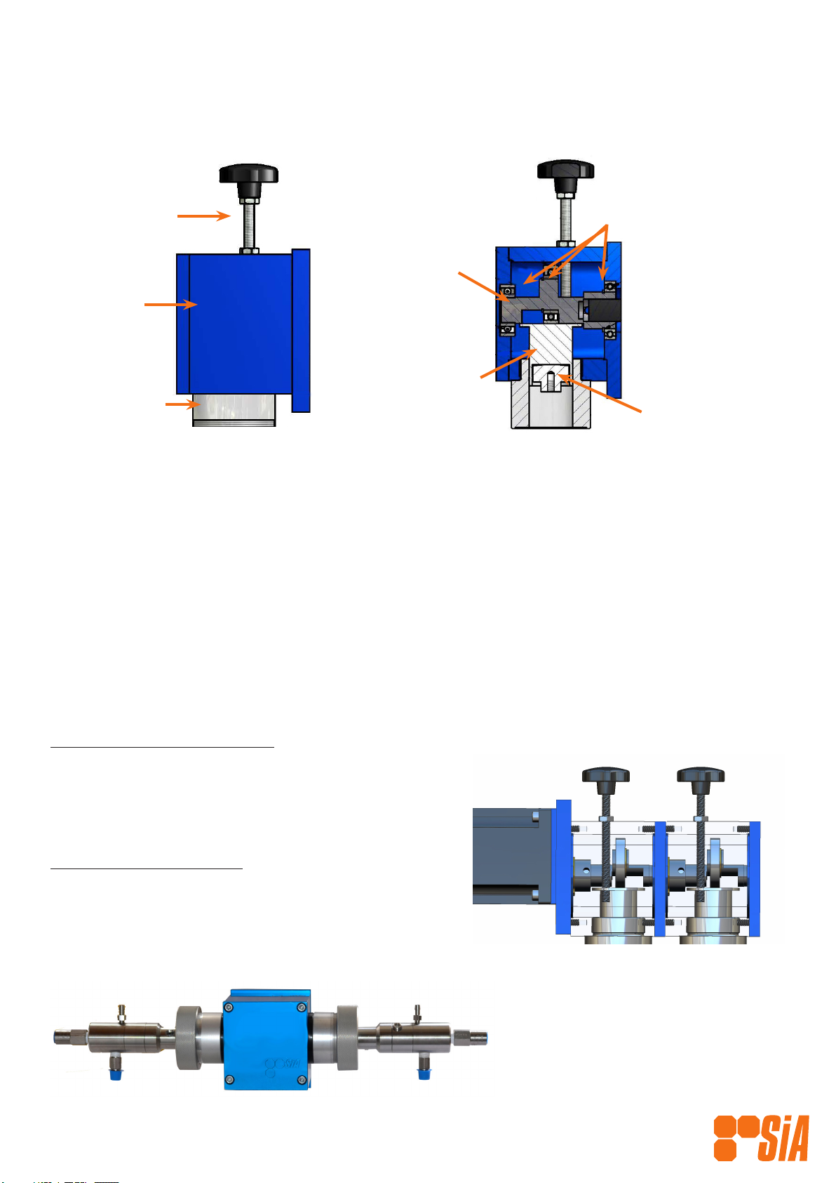
1.0 Drive Assembly
Drive Assembly Main Components
1.01 How the Drive Works
The SiA Drive Assembly has been designed to give a reliable means of driving a reciprocating
chemical injection pump by means of electricity in general, and solar energy in particular.
The standard motive force of the Drive Assembly consists of a PMDC, BLDC or A.C. motor driving
through an integrally mounted gearbox. This gear-motor mounts directly to the drive case’s ange
mount and the drive shaft connects to the drive crank shaft via a keyed connection. The crank
shaft is supported either end by oversized sealed bearings so as to eliminate all overhung loads.
This greatly increases the life of the gear-motor’s gearbox.
By applying a rotary force to the end of the crank shaft, the force is transmitted to the pump by
way of the plunger adaptor, which is directly acting on the pump plunger.
Multiplex Drive Conguration
The SiA multiplex conguration works as described
above, with the added benet of allowing combined or
multiple separate chemical ows in the one chemical
injection pump.
Liquid End Congurations
Simplex— One liquid end per drive case with Stroke
Adjustment.
Duplex— Two liquid ends per drive case without Stroke
Adjustment
Multiplex 2 Conguration
Duplex Conguration
Manual Stroke
Length Adjustor
Drive Case
Pump Adaptor
Bearings
Crank Shaft
Plunger Adaptor
Upper Plunger Adaptor
Lower

6
1.1 Liquid End
Liquid End Main Components
1.2 Motor & Gearbox
A number of motor/gearbox options are available with SiA pumps depending on your application’s
requirements. The table below provides an outline of these different options, refer to the Parts List
at the front of this manual for part numbers specic to your pump.
Voltage Watts Ratio Gearbox Type Hazardous Area
Certications
Standard
12; 24;
120/240;
220/415;
20; 40; 60;
90; 120;
150;
50; 75; 150 Spur N/A
Standard BLDC
12; 24;
100; 120; 200;
400;
40; 50; Spur N/A
Heavy Duty
(Motor Optional)
12; 24;
120/240;
220/415;
Motor
dependant
26; 32 Planetary IECex;
ATEX;
UL/CSA
SiA Pump
Connection Ring
Body Upper
Body Middle
Bleed Screw
Body Lower
Check Valve Inlet
Check Valve
Outlet
Flange
Plunger
Return Spring
Seals
7
SECTION 2 INSTALLATION
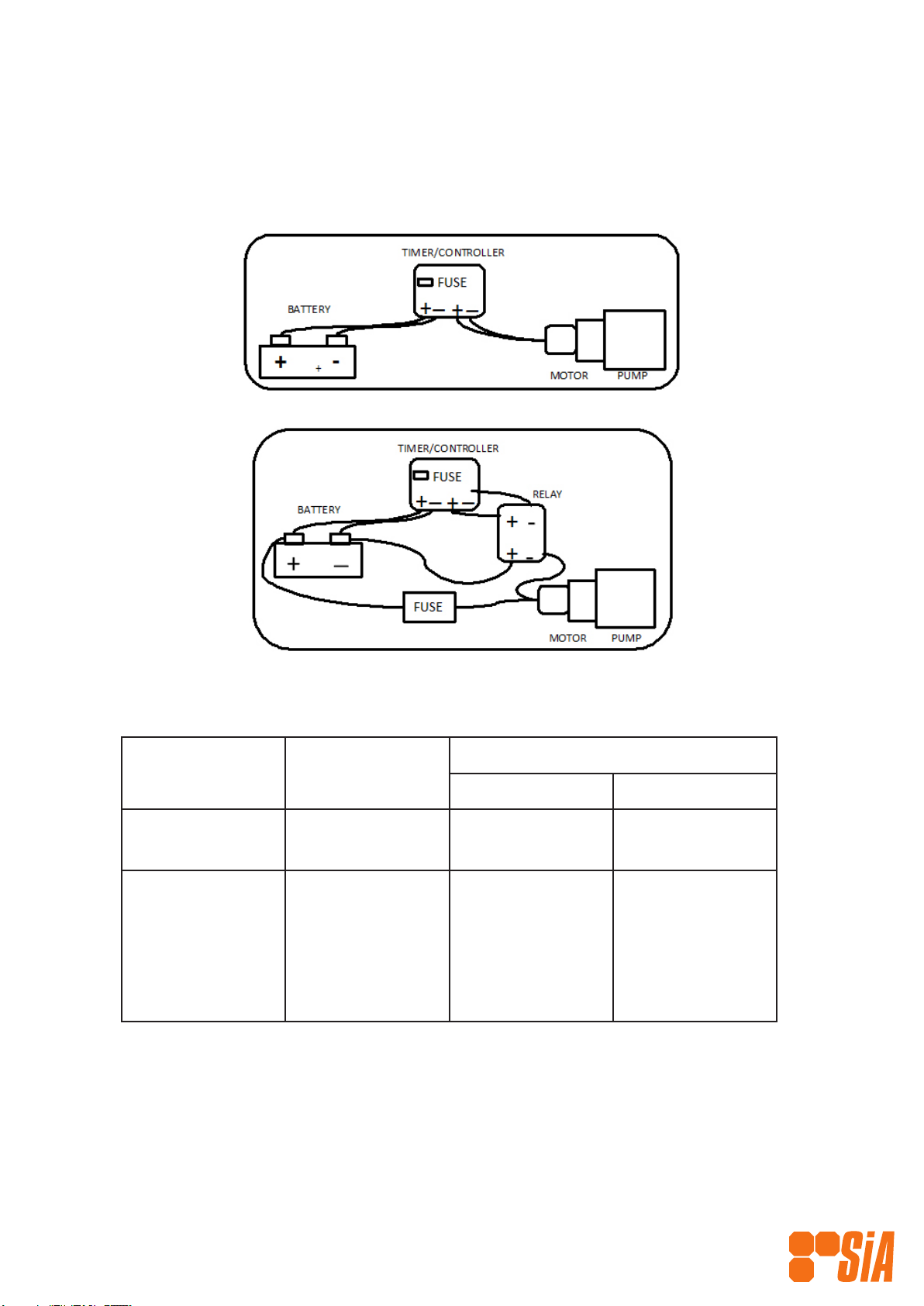
2.0 Fuses (PLEASE READ BEFORE INSTALLING)
Always ensure the correct fuse is tted and connections are as per diagrams below to prevent
damage to the pump that could void warranty.
Always ensure the correct fuse is tted and connections are as per diagrams below to prevent
damage to the pump that could void warranty.
Motor
Wattage
FUSE REQUIRED
12 Volt 24 Volt
High Eciency 150
100 (IEC)
NA
NA
7.5 amp
5 amp
Standard 40
60
90
120
150
5 amp
10 amp
15 amp
20 amp
25 amp
2.5 amp
5 amp
7.5 amp
10 amp
12.5 amp
For other wattage motors, or where no motor is supplied with the pump, please consult Solar
Injection Australia to ensure correct fuse.
If the motor is being driven directly via an SIAT71500 Timer/Controller the maximum fuse rating
is 10 amp.
Note: Drive case is limited to maximum input of 22 Nm, maximum of 150 Watts at 60 rpm. For
loads above this, our Heavy Duty Drive should be used.

8
2.1 Mounting,Orientation & Environment
The preferred orientation for mounting is with the Liquid End pointing down, the Timer Module
on top and the Gearmotor horizontal to the ground. This facilitates “bleeding” of the pump and
maximises the life of the seals within the pump. The inlet of the Liquid End should be no higher
than level with the lowest chemical level, to ensure a positive head on the inlet check valve. With
Duplex congurations (ie 2 liquid ends on 1 drive), the Liquid Ends will be horizontal to the ground
and the position of the inlet and outlet check valves will be reversed. Ensure that the inlet check
valves, which are gravity-style, are facing downwards.
We recommend installing the assembly within a weatherproof enclosure. Where this is not practical,
ensure as much weather and dust protection is afforded the whole assembly and the motor in
particular. An SiA custom cover for the motor and gearbox assembly can be ordered separately if
required.
Where environmental conditions are harsh, ie very wet, where there is salt water &/or dust or
snow, consider coating the assembly with an appropriate coating or cover. In wet conditions in
particular, we recommend use of a non hardening mastic on all mating parts, which is available
as an option. Please contact Solar Injection Australia or an SiA Authorised Technical Agent before
nalising the design of the installation.
Use the two M6 mounting holes to securely mount the assembly to any rigid frame or sub-
assembly with mounting brackets (not supplied but available).
2.2 Installation — Step by Step
1. Discard all plastic closures on the Liquid End and align pump connections as dictated by your
overall system design.
2. Connect the suction check valve to a gravity-fed chemical source. This pump requires a ooded
suction. We recommend installation of lters to the suction of each Liquid End and some form
of pump inlet isolation. Warranty may be affected if you do not.
3. Connect the discharge check valve to the process line. We recommend installation of a pressure
relief valve to the discharge of each Liquid End. Warranty may be affected if you do not.
4. Check that the pump adaptor ring is rm.
5. Open the bleeder valve until chemical starts to ow then re-tighten.
6. Ensure that the DC power supply that you are using corresponds to the DC power required. 12
volts supply to 12 volts equipment. 24 volts supply to 24 volts equipment
WARNING: Ensure the DC power supply to the DC Drive Motor is fused with the correct
fuse. See Section 2.0 for details.
WARNING: For AC models, all AC equipment must be installed by licenced electrical
personnel.
7. Before connecting the supply leads to the DC motor make ensure the supply is isolated.
8. Connect motor power leads to supply, Red to Red (+) and Black to Black (-).
If installing with an SIAT75001 Timer/Controller, connect the battery power supply and
motor leads to the four screw terminals clearly marked and located on the lower front
face of the timer.
WARNING: Connecting the main power supply in the reverse polarity can cause
immediate failure of the electronics within the timer module.
WARNING: As the control and isolation of the DC Drive is supplied by the operator,
care must be taken in selecting equipment to carry out these functions. We recommend
discussing alternative operator-designed control methods prior to installation.
9
SIAT75001 SiA Smart Controller
Revision: TH1
QUICK START GUIDE
Thank you for purchasing an SiA Smart Controller.
INSTALLATION
Physical Installation
Use the DIN Rail mounts at the back of the controller to mount timer within a suitable enclosure.
Ensure the enclosure provides a dry, well-ventilated environment that prevents
direct sunlight reaching timer.
The SIAT75001 must not be installed or operated in a dened Hazardous Area.
Important Information Before Connecting Power to the Controller
1. Ensure the correct rated fuse is installed in the Fuse Holder.
Refer to Fuses Section for details
2. Ensure your have correctly wired the power connections to the
Power Terminal Header (PTH).
3. Ensure only either 12 VDC or 24 VDC power is connected to the
“IN” terminals.
NOTE:As the controller will always return to the state it was last in before power was disconnected, the timer could
give an output to the Motor Terminals on the PTH immediately when the power is connected. To avoid this, t an
On/Off isolating switch between the timer’s Motor Terminals on the PTH and the motor’s terminals.
Fuses
It is very important that the correctly sized fuse is installed on the Controller. We suggest using Littlefuse ATO
Automotive Quick Acting Fuses.
Never use a fuse greater than 20 amps.
Choose a fuse that is suited for the protection of other equipment within the electrical circuit (providing it calls for
a fuse of no more than 20amps). Usually, the most important piece of equipment within the timer circuit is the DC
Motor. To work out the appropriate fuse rating to protect the motor, refer to the data-plate attached to the motor.
For SiA PMDC motors the following table is a guide:
Power
(watts)
Voltage Recommended
Max. Fuse Rating
25 12 5
25 24 2
40 12 5
40 24 3
60 12 10
60 24 5
Power
(watts)
Voltage Recommended
Max. Fuse Rating
90 12 10
90 24 5
120 12 15
120 24 7.5
HE 24 5
If the motor power selected requires a fuse greater than 15 amps, SiA recommends the use of a suitable relay that
can carry the extra load required.
SECTION 3 PUMP OPERATION
3.0 Operating Pump with SiA Timer/Controller: SIAT75001

10
OPERATION
First time connection of power (standard software & default settings)
It is important to review the default settings (see table below). Please note your controller may have been pre-
programmed to your application’s specications.
Setting Setting Purpose Default
Value
All Values
Units The type of units used. Metric Metric; US
Power On State Sets what happens to
the Timer when power is
applied.
Resume
Mode Sets the pump running
conditions.
Auto Cont - Pumps continuously
Auto - Pumps to chosen Flow Rate
Fixed - Pumps to chosen On/Off Times.
Batch - Pumps to chosen On/Off Times
at different times/days of week.
On Time Sets the On Time (in
seconds) used in Fixed
Mode
2 1 - 60
Off Time Sets the Off Time (in
seconds) used in Fixed
Mode
10 1 - 60
Flow Rate Sets the desired ow rate in
Auto Mode.
1.0 LPH
Pump Size Aligns the Timer with the
pump size.
L25 1/4” L15 1/8” L75 3/4”
L25 1/4” L100 1”
L35 3/8” L150 1 1/2”
L50 1/2” L225 2 1/4”
Battery Voltage Sets the battery voltage. Auto 12V; 24V; AUTO
Low Power
Voltage
Sets the battery voltage
that will trigger Low Power
Mode.
12.1
Cut Out Voltage Sets the battery voltage that
will turn the pump off.
11.8
Restore Voltage Sets the battery voltage that
will turn the pump back on
after Cut Out.
11.9
Power Save
Percentage Sets the percentage of the
ow rate in Low Power
Mode.
50
SIAT75001 SiA Smart Controller
Revision: TH1
11
Select Mode
1. Depress the ‘+’ & ‘-’ buttons until ‘Mode Select’
appears on the screen.
2. Depress “Select” button and cycle to required
mode.
3. Depress “Select” again to select.
4. Depress the “Back”button to return to the
“Start Timer” screen and start controller as per
step 2.
OPERATION (cont.)
Show Current Settings
1. Depress the ‘+’ & ‘-’ buttons until ‘Show Settings’
appears on the screen.
2. Depress “Select” button to cycle through settings.
3. Depress “Back” to exit.
4
5
Set Units
1. Ensure the controller has power on and the display shows as per on the previous page.
2. Depress the ‘+’ twice or until the display shows ‘OPTIONS’ and then depress the ‘Select’ button.
3. Depress the ‘+’ or ‘-’ buttons until the display shows ‘UNITS’ and then depress the ‘Select’ button.
4. Use the ‘+’ or ‘-’ buttons to choose either ‘Metric LPH’ or ‘US GPH’ and then depress the ‘Select’ button.
5. From here you can either depress the ‘Back’ button until the display shows as per to start the controller
or you can go on to set other parameters such as ‘PUMP SIZE’; FLOW RATE’; or ‘MODE SELECT’.
1
1
6
Set Pump Size
1. Ensure the controller has power on and the display shows as per on the previous page.
2. Depress the ‘+’ twice or until the display shows ‘OPTIONS’ and then depress the ‘Select’ button.
3. Depress the ‘+’ or ‘-’ buttons until the display shows ‘PUMP SIZE’ and then depress the ‘Select’ button.
4. Use the ‘+’ or ‘-’ buttons to get to the correct pump size (e.g ‘L150 1 1/2” ’)and then depress the ‘Select’
button.
5. From here you can either depress the ‘Back’ button until the display shows as per to start the controller
or you can go on to set other parameters such as ‘UNITS’; FLOW RATE’ or ‘MODE SELECT’.
1
1
Set Flow Rate
1. Ensure the controller has power on and the display shows as per on the previous page.
2. Depress the ‘+’ twice or until the display shows ‘OPTIONS’ and then depress the ‘Select’ button.
3. Depress the ‘+’ or ‘-’ buttons until the display shows ‘FLOW RATE...’ and then depress the ‘Select’ button.
4. Use the ‘+’ or ‘-’ buttons to set your desired ow rate (in LPH or GPH depending on the UNITS selected
previously), and then depress the ‘Select’ button.
5. From here you can either depress the ‘Back’ button until the display shows as per to start the controller or
you can go on to set other parameters such as ‘UNITS’; PUMP SIZE’ or ‘MODE SELECT’.
7
8
1
1
SIAT75001 SiA Smart Controller
Revision: TH1
12
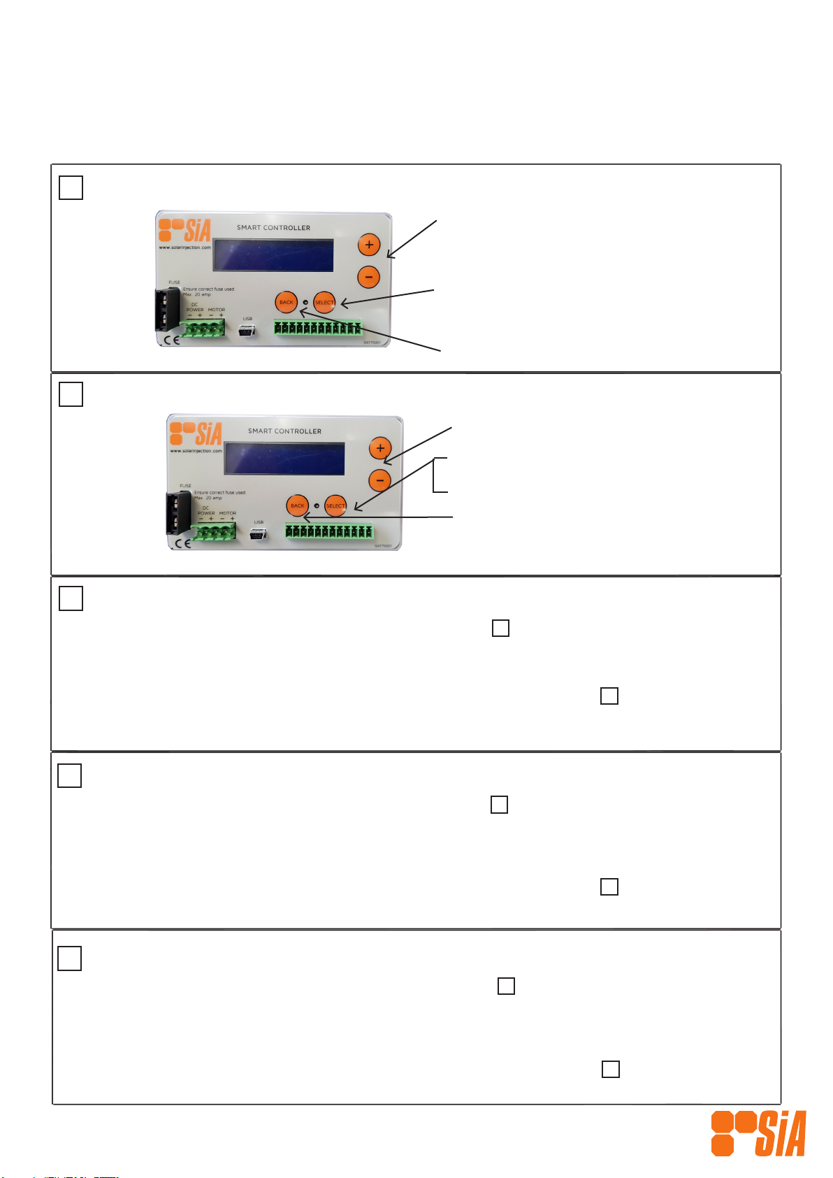
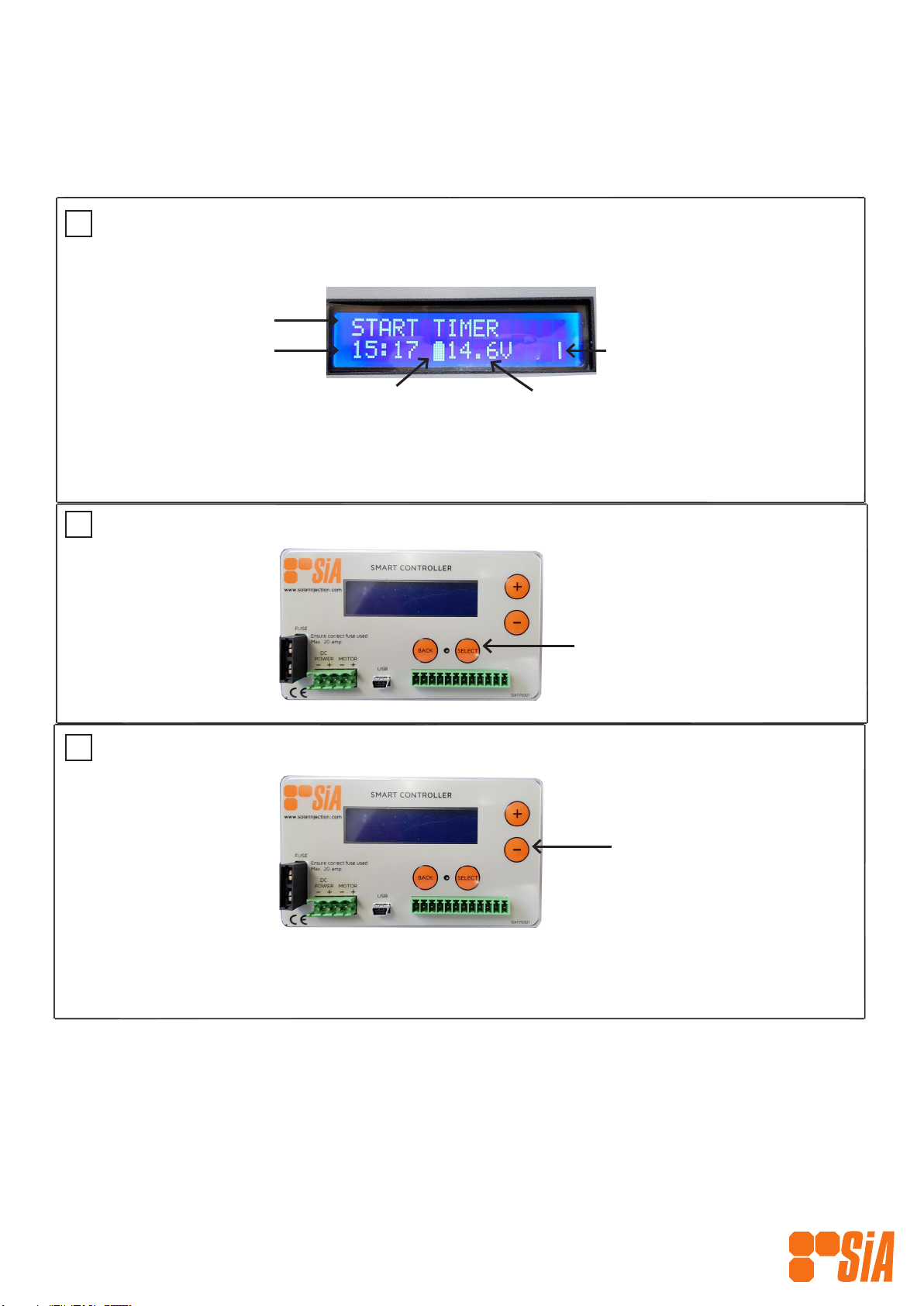
Stop Timer
Depress the ‘+’ button
until you cycle to the ‘Stop
Timer’ screen and then press
‘Select’.
Alternate option for stopping the Timer:
1. Cycle to the ‘Kill Timer’ screen by pressing the ‘+’ button and then press ‘Select’ to initiate the operation
command. This will stop the Controller instantly, turning the pump off if it was on.
OPERATION (cont.)
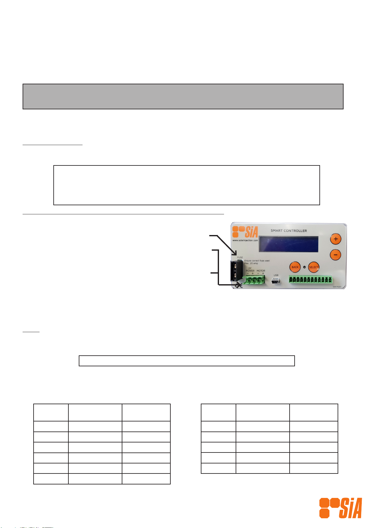
1Power On
LCD DISPLAY
When rotating, indicates
Controller is running.
Clock
Indictaes operation
Start Timer
Depress ‘Select’ button to
quick start Controller from
this screen.
Battery Status Voltage
Full - normal state
Half - low power state
Empty - power cut state
Note: This will stop the Controller at the next ‘Pump Off’ state ie if the pump is running when you are pressing
the ‘Select’ button, it will continue until the pump is in an “off’ state.
2
3
SIAT75001 SiA Smart Controller
Revision: TH1

13
3.1 Chemical Injection Flow Rate Adjustment
There are two ways of adjusting the injection ow rate, 1) electronic variable ow and 2) stroke
length adjustment .
The two methods can be used together to nely tune the ow rate.
Depending on the type of electric motor selected, two types of electric variable ow control can
be achieved. The cycles per minute (cpm) can be altered from maximum by either slowing the
electric motor with an electronic variable speed control device or preferably by using a Cycle Timer
to ‘start’, ‘stop’ and vary the ‘stop’ time of the electric motor. We recommend using a cycle timer
as it is simpler, more cost effective, robust, capable of operating at more extreme ambients and
has been found to use less energy per volume of chemical injected.
Solar Injection Australia manufactures a range of DC Timers, please contact us or an SiA Distributor
for details.
3.11 Electronic Variable Flow Adjustment
All drives, except those with a Duplex Liquid End conguration (ie 2 liquid ends on the 1 drive),
are tted with a mechanical stroke length adjustor that allows the operator to adjust the length
of the stroke and therefore the output per cycle innitely between 0% and 100% while the pump
is running.
Simply twist the adjustor until the desired ow is achieved. The lock nut provided will hold the
chosen setting.
An optional micrometer stroke adjustor is available on request.
3.12 Stroke Length Adjustment
Manual Stroke
Length Adjustor
Lock Nut

14
SECTION 2 MAINTENANCE
4.0 Routine Maintenance: Drive Assembly
Providing the Drive Assembly is selected and installed correctly, the Drive should perform for a
long period of time with little or no routine maintenance. We recommend however, that checks
are made at least every 6 months. The only wearing parts of the Drive are the Bearings and the
Plunger Adaptors.
4.01 Bearings
Inspection of the bearings should take place regularly. If operating in clean and dry conditions we
recommend 6 monthly inspections of moving parts. If operating in wet and/or dirty conditions,
we recommend more frequent inspections, starting with monthly inspections until the operator is
comfortable with longer service intervals.
To inspect bearings, follow these steps (refer to ILLUSTRATION & PARTS LIST, Page 2):
1. For Simplex pumps, ensure the Liquid End is facing downwards, so that no liquid runs into the
Drive Case.
2. For all pump congurations unscrew the Pump Connection Ring by hand to loosen and remove
the Liquid End/s.
3. Remove the Gearmotor or Gearbox by removing the 4 long screws attaching it to the Drive
Case
4. Unscrew the Bearing End Plate by removing the 4 screws
5. Remove the Crank Shaft and Bearings and inspect. You may need to move the Plunger Adaptor/s
to enable you to do this.
WARNING: Should the bearings become worn in any way they should be replaced
immediately with new parts available from Solar Injection Australia or SiA Distributors.
6. Place the Crank Shaft and Bearings (or replacement Bearings) into the Drive Case
7. Place the Bearing End Plate back on the Drive Case and secure with the 4 screws
8. Reattach the Liquid End/s and tighten the Pump Connection Ring/s. You may need to carefully
push down and hold the Plunger into the Liquid End to enable you to do this.
9. Position the Gearmotor or Gearbox back on the Drive Case and secure with the 4 screws.
All three Precision Roller Bearings are sealed type and do not require in-eld lubrication. They
have been selected using design loads far in excess of the loads that should be generated by the
design limitations of the product. Providing no moisture or dirt penetrates and that the Drive is
used in accordance with its design parameters a long life can be expected.
We have both Ertalyte and stainless steel versions of our Plunger Adaptors. No grease is applied
on assembly and providing abrasive dirt does not come between the Cam Bearing and the Plunger
Adaptor, negligible wear should take place through millions of cycles. If replacing Plunger Adaptor/s,
ensure you replace like for like as Ertalyte and stainless steel versions are not interchangeable.
To inspect Plunger Adaptor/s follow the steps outlined above for inspecting Bearings. After step 5,
remove and inspect Plunger Adaptor/s and then replace and continue to follow steps 6—9.
4.02 Plunger Adaptors

15
4.1 Routine Maintenance: SiA Liquid Ends
The maintenance of any Chemical Injection Pump (CIP)/Liquid End, other than an SiA unit is not
covered in this document.
WARNING: Solar Injection Australia accepts no responsibility should a Liquid End be tted
to an SiA Drive without rst seeking a recommendation from SiA to ensure correct
matching of the Gearmotor, Drive and Liquid End (pump).
4.10 Pressure Seal Grease
Check main pressure seal grease periodically and rell when necessary. This is done by removing
the Lube Plug on the side of the Liquid End and if required, injecting a small quantity of SiA
approved grease.
CAUTION: If injecting chemicals that cause the lubricant to foam, select an alternative
lubricant compatible with the injected uid. When it is essential that the injected
chemical must have a high level of purity, use distilled water as the lubricant.
4.11 Injection Chemicals
Ensure the chemicals being injected are clean and free of foreign matter to prevent damage to the
seal and the Liquid End’s plunger assembly. We recommend the installation of a suitable chemical
lter.
4.12 Seals
Check the seals regularly. Seal material and chemical compatibility is paramount. Our standard
plunger seal (TS) is a specially formulated PTFE and stainless steel compound that is energized
with a Viton o’ring, which is compatible with most chemicals, however we do have numerous
alternative materials available, please consult Solar Injection Australia or an SiA Distributor for
further assistance with choosing the right seal or when changing the chemicals you are injecting.
To inspect Seals & Back Ups follow these steps (refer to ILLUSTRATION & PARTS LIST,Page 2):
1. For Simplex pumps, ensure the Liquid End is facing downwards, so that no liquid runs into the
Drive Case.
2. For all pump congurations unscrew the Pump Connection Ring by hand to loosen and remove
the Liquid End/s.
3. Carefully remove the Plunger section and place gently on a at surface.
4. Remove the Flange and the Pump Connection Ring
5. Unscrew the three parts of the Pump Body (Upper, Middle, Lower)
6. Very carefully remove the Back Ups and Seals using either the plunger or a brass or plastic pick.
To use the plunger, insert it into the pump body below the seal and push the seal and back up
out. To use the pick, hook the seal and back up carefully and pull them out.
CAUTION: Be very careful not to damage the seal or other surfaces when extracting.
7. Replace the Seals and Back ups and then Follow Steps 1– 5 in reverse to complete.

16
4.2 Routine Maintenance: Gearmotors tted to the Drive
Generally, the gearmotor does not require routine maintenance other than periodic brush
replacement on our Standard DC models. Apart from these brushes there are no service parts
available. Should the DC gearmotor fail (or separately the motor or gearbox), we recommend the
whole DC gearmotor be replaced with a new unit, available from Solar Injection Australia or an
SiA distributor.
We recommend that the brushes be inspected as often as practical until the operator obtains
experience of the expected brush life for each situation, but at least every 6 months.
Note: There are no brushes in a BLDC Motor.
To inspect and or replace brushes on our Standard PMDC Gearmotor models, please follow the
steps below:
1. Disconnect power to pump before any servicing takes place.
2. Use large at blade screwdriver to unthread the plastic caps on either side of the motor.
3. Remove the brushes carefully (they are spring loaded).
4. Examine them. They should be at least 1/8” thick. If they are not, replace them. They will not
last much longer.
5. Replace new brushes into the holes on either side of the motor’s outer shell and rethread the
plastic caps.
6. As with the moving internals of the Drive, the operator can expect longer service intervals and
life by keeping the gearmotor clean and dry.
WARNING: Should the gearmotor show signs of wear in any way it should be replaced
immediately with new parts available from Solar Injection Australia or SiA Distributors.

17
4.3 Corrective Maintenance
Situation Cause Resolution
NO PUMP DISCHARGE • Suction &/or discharge check
valves not seating
• Pump vapour locked
• Suction or discharge line
plugged/blocked
• Clean or replace suction &/or
discharge check valves
• Open bleed plug & prime
• Check for closed isolating valve
• Check inlet and discharge lines for
blockage
PUMP DOES NOT CYCLE • Plunger stuck due to tight or
dry seal
• Process line pressure too high
for unit selected
• Blown fuse
• No power supply to DC motor
drive
• Timer switch in OFF position
• Timer set to minimum cycle
rate
• Check seal, if swollen , check
chemical compatibility and replace
• Check selection and ensure
discharge line is not blocked
• Check and replace fuse in DC
supply. If this condition repeats
itself, check the drive mechanism
for seizure.
• Check and connect correct power
supply
• Set switch to CONTINUOUS for
testing
• Adjust timer accordingly
SHORT SEAL LIFE • Nick, Burr or scratches on
plunger
• Seal &/or plunger materials not
compatible with chemical being
injected
• Lack of lubricant
• Incorrect lubricant or chemical
crystallising on plunger and
scoring seal/plunger
• Replace plunger
• Refer to chemical compatibility
charts or contact Solar Injection
Australia
• Maintain visible lubricant level in
reservoir.
• Change lubricant to be compatible
with chemicals being pumped.

18
APPENDIX: CHEMICAL COMPATIBILITY CHART
Key to Rating: A - Substantial Resistance, B - Moderate Resistance, C - Severe Effect, Blank - No Data
Corrosive Agent Steel 304 SS 316 SS C-20 Teflon PVC Viton Buna-N Fluoraz
Acetaldehyde B A A A A C C B C
Acetate Solvents B A A A A C C C C
AceticAcid,20% B A A A A A C A C
Acetic Acid Concentrated to
l5O°F(66° C)
B A A A C C C
Acetic Acid Concentrated to
2l2°F(100 C )
C B A A A C C C
Acetic Anhydride C B A A A C C A C
Acetone B A A A A C C B C
Alum C C B A A A A A A
Aluminum Chloride C C C B A A A A A
Aluminum Nitrate B A A A A A A
Aluminum Sulfate C C B A A A A A A
Ammonia Anhydrous A A A A A C A A
Ammonium Bicarbonate A A A A A A A C
Ammonium Bisulfite B A A A A A A
Ammonium Bifluoride C B B A A A A
Ammonium Hydroxide C A A A A A B A A
Ammonium Nitrate B A A A A A B C
Ammonium Phosphate C B A A A A A A
Ammonium Sulfate C B B B A A A A C
Ammonium Sulfite C A A A A A A
Amyl Acetate Dry A A A A A C C C C
Amyl Alcohol A A A A A B A A B
Amyl Chloride C B A A A C C C
Aniline Chloride C B A A A B
Aniline Dyes C A A A A C B C
Animal Fats and Oils A A A A A A C A
Aqua Regia C C C C A B C
Ascorbic Acid C A A A A
Barium Chloride C C C B A A A A A
Barium Sulfite B A A A A A A A
Benzaldehyde B A A A A C C C
Benzene A A A A A C B C C
Benzene Sulfonic Acid lO% C B B A A A A C C
Benzoic Acid C B B A A A C A
Benzoyl Chloride C C C C A B
Boric Acid C A A A A A A A A
Bromine Anhydrous C C C B A C A C C
Bromine Dilute C C C C A B A C C
Bromine Trifluoride C C B B A C C
Butadiene C A A A A A C
Butane B A A A A A A A A
Butyric Acid 2O% C A A A A C A A
Butyric Acid, Concentrated C B B B A C A
Calcium Bisulfite B A A A A A A A A
Calcium Carbonate AAAAAAAAA
Calcium Chlorate C A A A A A A A A
Calcium Chloride C B B A A A A A A
Calcium Hydroxide AAAAAAAAA
Calcium Hypochlorite C C C C A A A C A
Calcium Nitrate C A A A A A A
Calcium Sulfite C A A A A A A
Calcium Sulfate A A A A A A C
Camphor Alcohol Sol B A A A A
Carbon Disulfide C A A A A A C
Carbon Tetrachloride Dry B A A A A C C
Carbon Tetrachloride Wet C B B B A C C C
Carbon Water Slurries C B A A A A A A
Cesium, 260°F(127°C) C A A A A C C
Chlorine, Anhydrous A A A A A C C C
Chlorine Water C C C A A A A C C
Chloroacetic Acid C C C C A C C
Chlorobenzene C A A A A C A B
Chloroform B A A A A C A C
Chlorosulfonic Acid C B B B A C C C B
Choline Chloride A A A A
Chromic Acid to l5O°F(66°C) C B B B A C A
Citric Acid C B B A A A A A A
Copper Chloride C C C C A A A A A
Copper Fluoride C B B B A A

19
Corrosive Agent Steel 304 SS 316 SS C-20 Teflon PVC Viton Buna-N Fluoraz
Copper Nitrate C B A A A A A A A
Copper Sulfate B A A A A A A A A
Cottonseed Oil A A A A A A A A
Creosols A A A A A C C C A
Cyclohexane B A A A A C A C A
Cyclohexanone B A A A A C C C B
Dichlorethane, Dry A A A A A C C C
Diethanolamine A A A A A C C A
Diethyl Benzene A A A A A C
Diethyl Ether A A A A A C C
Diethyl Sulfate C B B A A
Diethylene Glycol B A A A A A A A
Dimethyl Amine A A A A A C
Dimethyl Phthalate A A A A A C C B
Ether A A A A A C C C
Ethyl Acetate A A A A A C C C C
Ethyl Alcohol A A A A A A C A
Ethyl Benzene A A A A A A C
Ethyl Bromide C C C C A C
Ethyl Chloride C A A A A C A C A
Ethyl Mercaptan B A A A A C A C
Ethylene(Liquefied) A A A A A
Ethylene Dichioride C A A A A B C A
Ethylene Glycol B A A A A A A A A
Ethylene Oxide C A A A A C C C C
Fatty Acids C A A A A A A A
Ferric Chloride C C C C A A A A A
Ferric Nitrate C B B A A A A A
Ferric Sulfate C C B C A A A A A
Ferrous Chloride C C C C A A A A
Ferrous Sulfate C C C C A A A A
Filter Aid Slurries B AAAAAAA
Fluosilicic Acid C C C B A A A A
Copper Fluoride C B B B A A
Copper Nitrate C B A A A A A A A
Copper Sulfate B A A A A A A A A
Cottonseed Oil A A A A A A A A
Creosols A A A A A C C C A
Cyclohexane B A A A A C A C A
Cyclohexanone B A A A A C C C B
Dichlorethane, Dry A A A A A C C C
Diethanolamine A A A A A C C A
Diethyl Benzene A A A A A C
Diethyl Ether A A A A A C C
Diethyl Sulfate C B B A A
Diethylene Glycol B A A A A A A A
Dimethyl Amine A A A A A C
Dimethyl Phthalate A A A A A C C B
Ether A A A A A C C C
Ethyl Acetate A A A A A C C C C
Ethyl Alcohol A A A A A A C A
Ethyl Benzene A A A A A A C
Ethyl Bromide C C C C A C
Ethyl Chloride C A A A A C A C A
Ethyl Mercaptan B A A A A C A C
Ethylene(Liquefied) A A A A A
Ethylene Dichioride C A A A A B C A
Ethylene Glycol B A A A A A A A A
Ethylene Oxide C A A A A C C C C
Fatty Acids C A A A A A A A
Ferric Chloride C C C C A A A A A
Ferric Nitrate C B B A A A A A
Ferric Sulfate C C B C A A A A A
Ferrous Chloride C C C C A A A A
Ferrous Sulfate C C C C A A A A
Filter Aid Slurries B AAAAAAA
Fluosilicic Acid C C C B A A A A
Formaldehyde,80°F(27°C),Rm.
Temp
B B A A A B A A C
Formic Acid,80°F(27°C) C B A A A B B C A
CHEMICAL COMPATIBILITY CHART (continued)
Key to Rating: A - Substantial Resistance, B - Moderate Resistance, C - Severe Effect, Blank - No Data
Table of contents
Other SIA Water Pump manuals


Popular Water Pump manuals by other brands

EINHELL
EINHELL RG-GP 1355 NM Original operating instructions

Richter
Richter MNK Series Installation and operating manual

Wilo
Wilo CronoLine-IL Installation and operating instructions

Hydro-Force
Hydro-Force V115 manual

Everbilt
Everbilt LTS250A Use and care guide

Grundfos
Grundfos APG Series Installation and operating instructions

Draper
Draper SWP220A Instructions for use

Graf
Graf 202561 Instructions for installation

GORMAN-RUPP PUMPS
GORMAN-RUPP PUMPS 62 1/2A1-CH13 Series Installation, operation, and maintenance manual with parts list

Grundfos
Grundfos SCALA1 Installation and operating instructions

Everbilt
Everbilt UTA02510 quick start guide

Torrent
Torrent AP265 Installation and operating instructions


