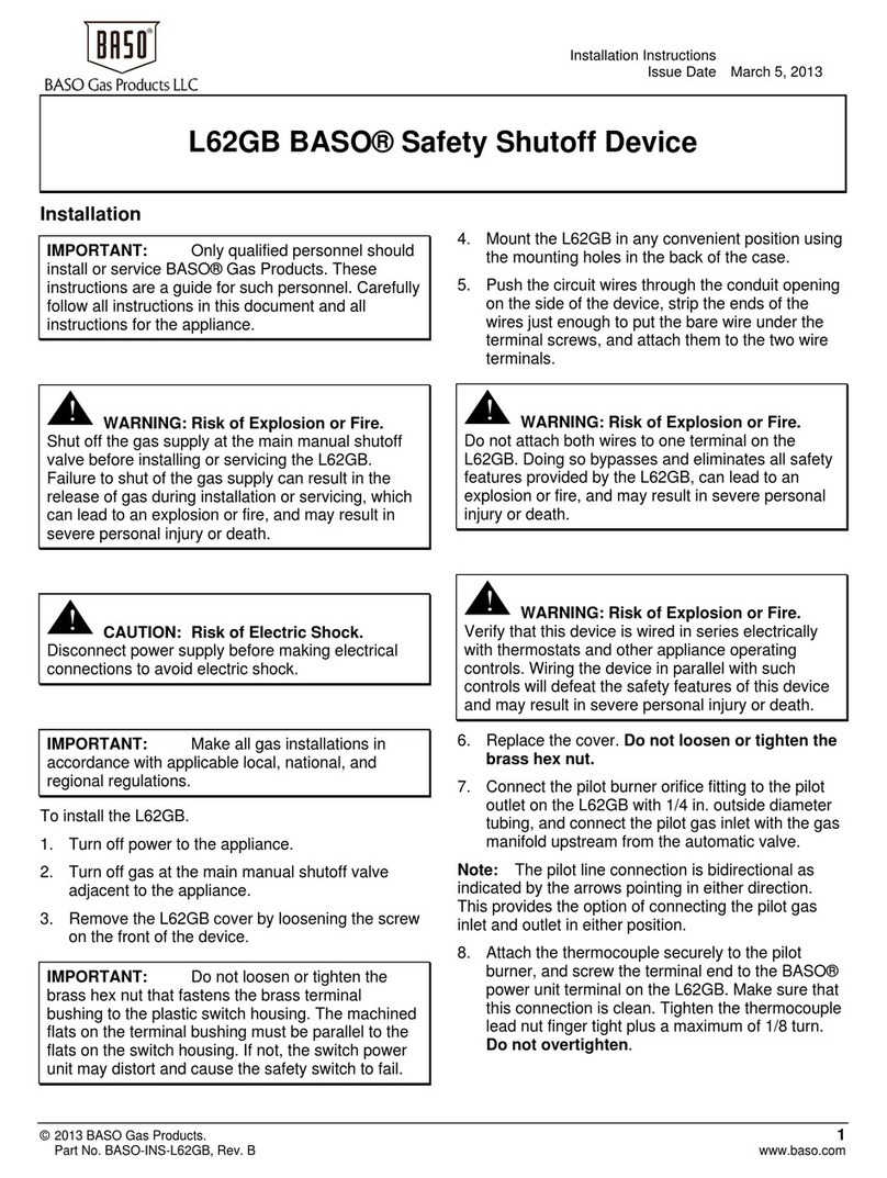
Baso L62AA User manual

Installation Instructions
Issue Date May 14, 2007
© 2007 BASO Gas Products 1
Part No. BASO-INS-L62AA, Rev. - www.baso.com
L62AA BASO® Safety Shutoff Device
Installation
IMPORTANT: This bulletin is intended as a
guide for authorized service personnel installing or
servicing BASO® Gas Products. Carefully follow
all instructions in this bulletin and all instructions
on the appliance. Limit repairs, adjustments, and
servicing to the operations listed in this bulletin or
on the appliance.
!
WARNING:Risk of Fire or Explosion.
The system must meet all applicable codes.
Improper installation may cause gas leaks,
explosions, property damage, and injuries.
!
WARNING: Risk of Fire or Explosion.
To prevent leakage of upstream gas, shut off the
gas supply at the main manual shutoff valve
before installing or servicing the L62AA safety
shutoff device.
!
WARNING: Risk of Shock.
Avoid electrical shock and equipment damage by
disconnecting the electrical power before wiring
the L62AA.
To install the L62AA.
1. Turn off power to the appliance.
2. Turn off gas at the main manual shutoff valve
adjacent to the appliance.
3. Remove the L62AA cover by loosening the
screws at the side of the device.
4. Mount the L62AA in any convenient position
using the mounting holes provided. See Figure 1
for mounting hole locations.
5. Push the circuit wires through the conduit
opening on the bottom of the L62AA, strip the
ends of the wires just enough to put the bare
wire under the terminal screws, and attach them
to the two wire terminals (see Figure 1).
6. Replace the cover.
7. Attache the thermocouple securely to the pilot
burner, and screw the terminal end to the BASO
power unit terminal on the L62AA (see Figure 1
and Figure 2). Make sure tat this connection is
clean. Tighten the thermocouple lead nut finger
tight plus a maximum of 1/8 turn. Do not
overtighten.
!
WARNING: Risk of Fire or Explosion.
Never attach both wires to one terminal. Doing so
eliminates all safety features provided by the
L62AA device.
!
WARNING: Risk of Fire or Explosion.
Always wire the safety shutoff device in series with
a thermostat or other such control. Wiring it in
parallel defeats the safety features of the L62AA
device.

2 L62AA BASO Safety Shutoff Device Installation Instructions
SAFETY MECHANISM
WARNING
EXPLOSION HAZARD
SERIOUS INJURY OR
DEATH CAN RESULT
DO NOT REMOVE SHIELD
0.206 in. (5.23 mm)
Diameter
Mounting Holes Reset
Button
Power Unit
Assembly
BASO Power
Unit Terminal
0.206 in. (5.23 mm)
Diameter
Mounting Hole
Wire
Terminals
Conduit
Opening
Figure 1: View of the L62AA Without the Cover
Red Lever
Transformer
Power Source
Thermostat
"X”
"X”
Main Manual
Shutoff Valve
(”A” Valve)
L62GB BASO
Safety Shutoff Device
Pilot Valve
(“B” Valve)
“X” indicates possible
locations for other controls.
Thermocouple
Lead
Pilot Gas
Outlet
Power Unit
Terminal
3 in. (76.2 mm)
Sediment
Trap
Pilot Gas
Inlet
Basotrol
Valve
Figure 2: Typical L62AA Installation

L62AA BASO Safety Shutoff Device Installation Instructions 3
Setup and Adjustments
Checkout
!
WARNING: Risk of Fire or Explosion.
Avoid personal injury or property damage by making
sure the safety shutoff device functions properly and
there are no gas leaks. Follow this checkout
procedure before leaving the installation.
Make sure all components are functioning properly by
performing the following test.
1. Test all joints and connections for leaks with a
soap solution.
2. Set the thermostat to the lowest setting.
3. Close the main manual shutoff valve (“A” valve)
and the pilot valve (“B” valve [see Figure 2]) and
wait at least five minutes for unburned gas to
escape from the appliance.
4. Reopen the “B” valve and ignite pilot gas. Wait for
30 to 45 seconds.
5. Push down the red indicator and aluminum reset
button to its full limit of travel and release. If the
red indicator remains depressed, the unit is
operative. If the red button does not stay
depressed, wait an additional 30 seconds and try
again. If the second attempt is not successful,
check that the thermocouple output meets the
value in Table 1.
6. Open the “A” valve after the red indicator button
remains in the depressed position. The main
burner will ignite from the pilot burner when the
thermostat calls for heat.
7. Disconnect the thermocouple from the L62AA. The
main valve should close immediately. If it does not
close, check for wiring errors. Reconnect the
thermocouple to the L62AA when it is operating
correctly.
8. Check the millivoltage output of the thermocouple
and milliampere dropout range at the BASO power
unit terminal to see that they meet the values in
Table 1 and Table 2. Step-by-step procedures for
these checks are included with the Y99AB BASO
Test Kit.
9. Re-light the pilot.
10. Observe at least three complete operating cycles
to make sure that all components are functioning
correctly.
11. Reset the thermostat to a normal temperature
setting before leaving the installation.

4 L62AA BASO Safety Shutoff Device Installation Instructions
Repairs and Replacement
Check the millivoltage output of the thermocouple and
milliampere dropout range at the BASO power unit
terminal to see that they meet the values in
Table 1 and Table 2 If the readings do not meet these
values, replace the thermocouple and/or the safety
shutoff device.
Table 1: Thermocouple Output
Thermocouple mV Range
Lead Type Turn
Down
Normal Not Less
Than
K15 4 mV 20-28 15
K16 4 mV 25-35 17
K19 4 mV 25-35 17
Table 2: L62AA Dropout Range
mA Range of Power Unit Assembly
Low High
100 300
Pilot Servicing
If pilot flame problems occur, check the following:
•If the pilot flame burns yellow it may be due to dirt
or lint covering the lower portion of the pilot
burner. Remove dirt and lint using a soft brush or
a vacuum.
•A flame approximately 1/2 in. (12.7 mm) high must
surround the thermocouple tip (see Figure 3
•Because this is an electrical connection, the
thermocouple lead connection to the BASO power
unit must be clean and free of grease.
Approximately
1/2 in. (12.7 mm)
Figure 3: Flame Position
Replacement Procedure
!
WARNING: Risk of Shock.
Avoid electrical shock and equipment damage by
disconnecting the electrical power before replacing
or rewiring the safety shutoff device.
!
WARNING: Risk of Fire or Explosion.
Turn off the gas at the main manual shutoff valve
next to the appliance before loosening any gas
connections.
!
WARNING: Risk of Fire or Explosion.
Label all wires prior to disconnection when servicing
controls. Wiring errors can cause improper and
dangerous operation.
When necessary, replace the safety shutoff device as
follows:
1. Turn off power to the appliance.
2. Close the main manual shutoff valve and the pilot
valve.
3. Disconnect the thermocouple lead from the safety
shutoff device.
4. Remove the cover.
5. Disconnect and label the wires from the two wire
terminals and remove the device from the
appliance.
6. Replace with the new BASO L62AA according to
the instructions in the Installation section.
7. Perform the Checkout section before leaving the
installation.
Repairs
Field repairs must not be made to the L62AA safety
shutoff device. If the thermocouple meets the output
listed in Table 1 and the valve does not function,
replace the entire device. Any attempt to repair this
assembly voids the manufacturer’s warranty. For a
replacement safety shutoff device, contact the nearest
BASO Gas Products distributor.

L62AA BASO Safety Shutoff Device Installation Instructions 5
Technical Data
Product L62AA BASO Safety Shutoff Device
100% Shutoff No
Conduit Opening 1 or 2 as Special
24/25 VAC 125 VAC 250 VAC 230 VDC Motor Rating 125/250 VACSwitch Contacts
Electrical Specifications * 8 A 3 A 0.06 A 1/4 hp
Ambient Temperature
Range -40 to 150°F (-40 to 66°C)
Reset Manual
Switch Action SPST
Type of Gas Natural
Packaging Bulk pack supplied to original equipment manufacturer (individual pack optional).
Bulk Pack Quantity 30
Weight 24 lb (10.9 kg)
Agency Listings CSA Certificate Number 229521-1656085
UL File Number MH2926
Specification Standards ANSI Standard Z21.20
CAN1-6.4
UL Standard 372
*Switch can be used on 24/25 VAC installation.
Performance specifications are nominal and conform to acceptable industry standards. All agency certification of BASO products is performed
under dry and controlled indoor environmental conditions. Use of BASO products beyond these conditions is not recommended and may void
the warranty. Product must be protected if exposed to water (dripping, spraying, rain, etc.) or other harsh environments. The original
equipment manufacturer or end user is responsible for the correct application of BASO products. Consult BASO Gas Products LLC for
questionable applications. BASO Gas Products LLC shall not be liable for damages or product malfunctions resulting from misapplication or
misuse of its products.
Refer to the L61, L62 Series BASO Safety Shutoff Device Product Bulletin (BASO-PB-L61/L62) for necessary information on operating and
performance specifications of this product.
1007 South 12th Street
PO Box 170
Watertown WI 53094 www.baso.com
1-877-227-6427 (1-877-BASOGAS) Printed in U.S.A.
Table of contents
Other Baso Security Sensor manuals
Popular Security Sensor manuals by other brands
Risco
Risco WatchU quick start guide
ADEC Technologies
ADEC Technologies TDC3 F-F-31 Series Quick reference guide
quiko
quiko QK-RADAR manual

Rielta
Rielta Ladoga MK-RK installation guide

ITALIANA SENSORI
ITALIANA SENSORI 8058-ISR044 Installation, operation and maintenance manual
Takex
Takex PXB-100SW instruction manual
