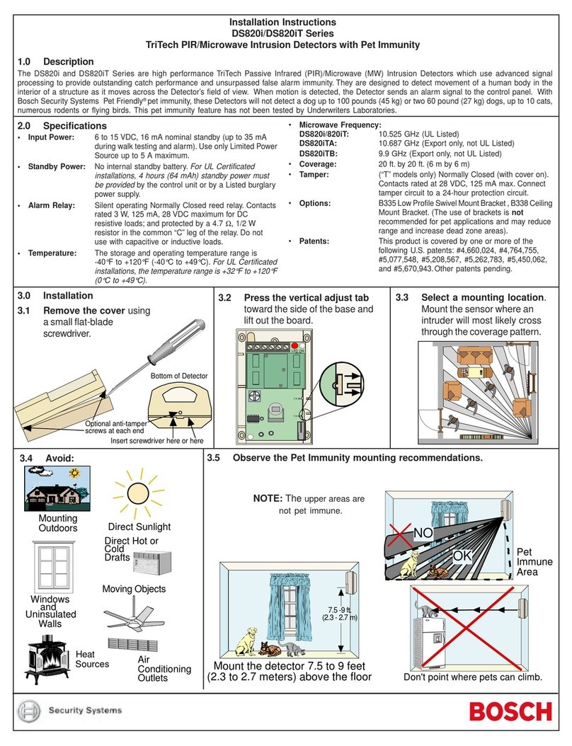
Page 2 © 2011 Bosch Security Systems, Inc. DS935Z Installation Instructions
- The angle adjust markings are on the mirror. Slide the
mirror forward or back until the angle hash marks are in-
line with the markers on each side of the frame.
3.0 Wiring
Only apply power after all connections have been
made and inspected.
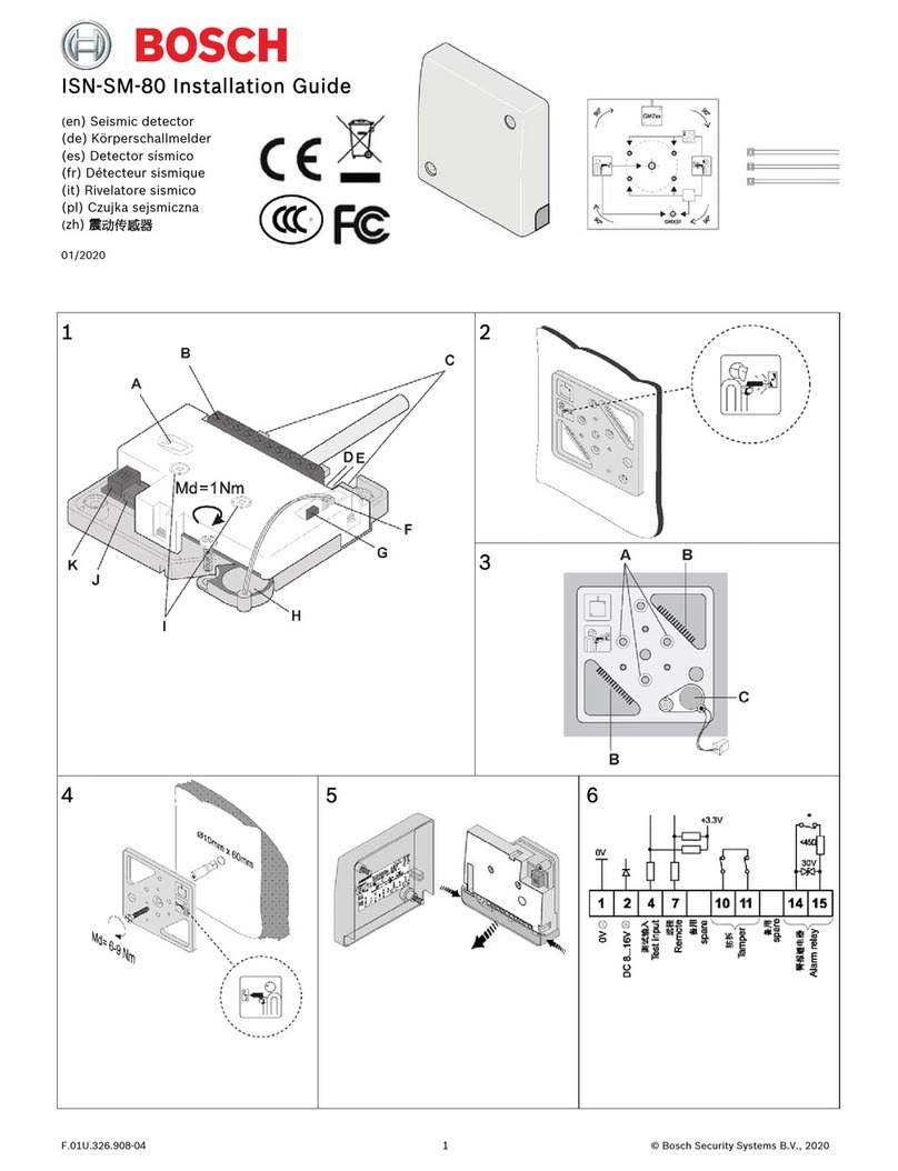
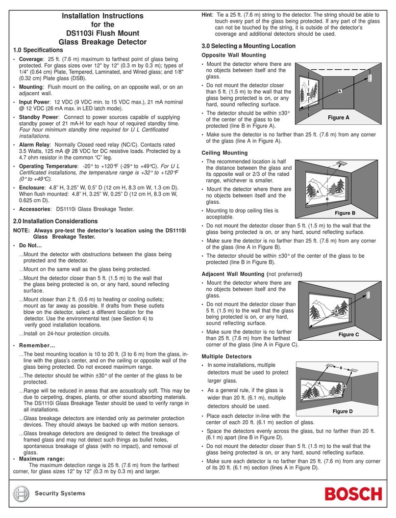
• Connect wiring as shown.
NOTE: Do not coil excess wiring inside unit.
• Seal the Wire Entrance using the foam plug provided.
Terminal Descriptions
•1 (-) & 2 (+): Input Power. Use no smaller than #22 AWG
(0.8 mm) wire pair.
•3, 4, 5: Form "C" reed relay contacts rated at 3 W, 125 mA,
28 VDC maximum for DC resistive loads and protected by a
4.7 ohm resistor in the common "C" leg of the relay. Do not use
with capacitive or inductive loads.
•6 & 7: Tamper Contact, rated 28 VDC, 125 mA.
•8: Trouble. Solid state open collector; maximum current load is
25 mA. Shorts to ground (-) when the detector is in a Trouble
condition.
5.0 Configuring Detector
1 ON = LED ON
1 OFF = LED OFF
2 ON = Standard
2 OFF = Intermediate
3 ON and 4 OFF = 4 Day Motion Monitor
3 OFF and 4 ON = 30 Day Motion Monitor
3 OFF and 4 OFF = Motion Monitor Disabled
OPEN
12 34
OFF
ON
(ON) 1
(OFF) 0
5.1 S1 - LED Operation
•ON: Allows the LED to operate when activated by alarm.
•OFF: The LED will not operate on alarm.
5.2 S2 - Sensitivity Mode
•Standard Sensitivity: Recommended setting for maximum
false alarm immunity. Tolerates environment extremes on this
setting. Not recommended for Long Range or Barrier type
patterns. The detector is shipped in Standard Sensitivity
mode.
•Intermediate Sensitivity: Recommendedsetting for anylocation
where an intruder is expected to cover only a small portion of the
protected area. Tolerates normal environments on this setting.
This setting will improve your intruder catch performance.
5.3 S3 and S4 - Motion Monitor:
Set for the desired Motion Monitor time (see Supervision
Features). The detector is shipped with the Motion Monitor
feature disabled.
6.0 Setup and Walk Testing
Before walk testing, the system should be fully wired,
powered, and programmed.
• Turn LED Switch ON.
• Replace the front cover.
NOTE: All testing must be performed with the front
cover in place.
• Wait at least two minutes (with no motion in the
coverage area) for the detector to setup.
• Walk test across the coverage pattern.
• The edge of the coverage is determined by activation of the
LED.
• Walk test the unit from both directions to determine the
boundaries.
7.0 Supervision Features
A supervision trouble condition is indicated at the detector by the
LED. The LED indicates the cause of the trouble using coded
pulses. The trouble signal activates the Trouble output available
at Terminal 8, which should be connected to a 24-hour zone.
The supervision features function as follows:
•PIR: PIRoperation is checkedelectronically approximately every
12 hours. If the circuit fails, the LED will pulse four times, the
Trouble output will activate and the unit must be replaced.
•Motion Monitor Supervision: This feature verifies that the
detector has a clear view of the detection area.
- When selected, a supervision timer is activated. A trouble
condition will be indicated if the detector has not alarmed at
least once during the selected time period (this feature can be
disabled by placing both switches [S3 and S4] in the OFF
position). The time period selected should be long enough to
allow adequate time for holiday weekends.
- If the time period selected has elapsed from the last alarm,
the LED will flash two times and the Trouble output will activate.
The following chart displays the LED response to the supervision
features: LED Cause
ON
Two Flashes
Four Flashes
Unit Alarm
Motion Monitor Timeout
PIR Self-Test Failure
(replace detector)
• Trouble Reset: An alarm activation will reset a motion monitor
trouble condition.
8.0 Maintenance
At least once a year, the range and coverage should be checked
in accordance with the Walk Testing section. To ensure continual
daily operation, the end user should be instructed to daily walk
through the outer edge of the coverage pattern and observe the
LED operation (if used). This assures an alarm output prior to
arming.
TR
-+
12345678
NO CNC TT
larm
larm
