Bastl CV Trinity User manual

CV Trinity hs 6 independent chnnels for CV genertion.
The generted signls re in the 0-5 volts rnge. Ech
ofthem cn be set to AUTOMATION (red), LFO (green)
orADSR (blue).
Use the SELECT buttons to select chnnel to edit. The
lyout of the 3 big buttons corresponds to the output
connector lyout. The 3 big buttons select the column
ndthe smll button select which row you re editing.
Theselected chnnel is indicted by the LEDs.
The SELECT OUT connector outputs copy of the CV from
the chnnel tht is selected for editing. The current signl
is indicted by n LED.
Pressing the mode button chnges between the modes.
The mode of the selected chnnel is indicted by the color
of the RGB LED. In ech mode the knobs hve different
functions which re indicted by the front pnel print.
Ech chnnel lso hs CV/gte/clock INPUT. The
function of these inputs depends on the selected mode
nd its settings.
Clk IN is used by AUTOMATION or LFO to synchronize to
mster clock.
Clk OUT outputs clock signl from the built-in clock
instruction
genertor. The clock genertor frequency cn be djusted
by holding the FN button nd turning the top knob. Clk
OUT is normlized to Clock IN.
The FN button lets you to ccess dditionl settings for
ech mode. While you hold the FN button the SELECT
buttons show the setting informtion bits. Plese refer
tothe mode description for detils.
The record button is used during utomtion to record
knob movement. If you press the record button while
holding the FN button CV Trinity sves ll settings for
llchnnels into preset.
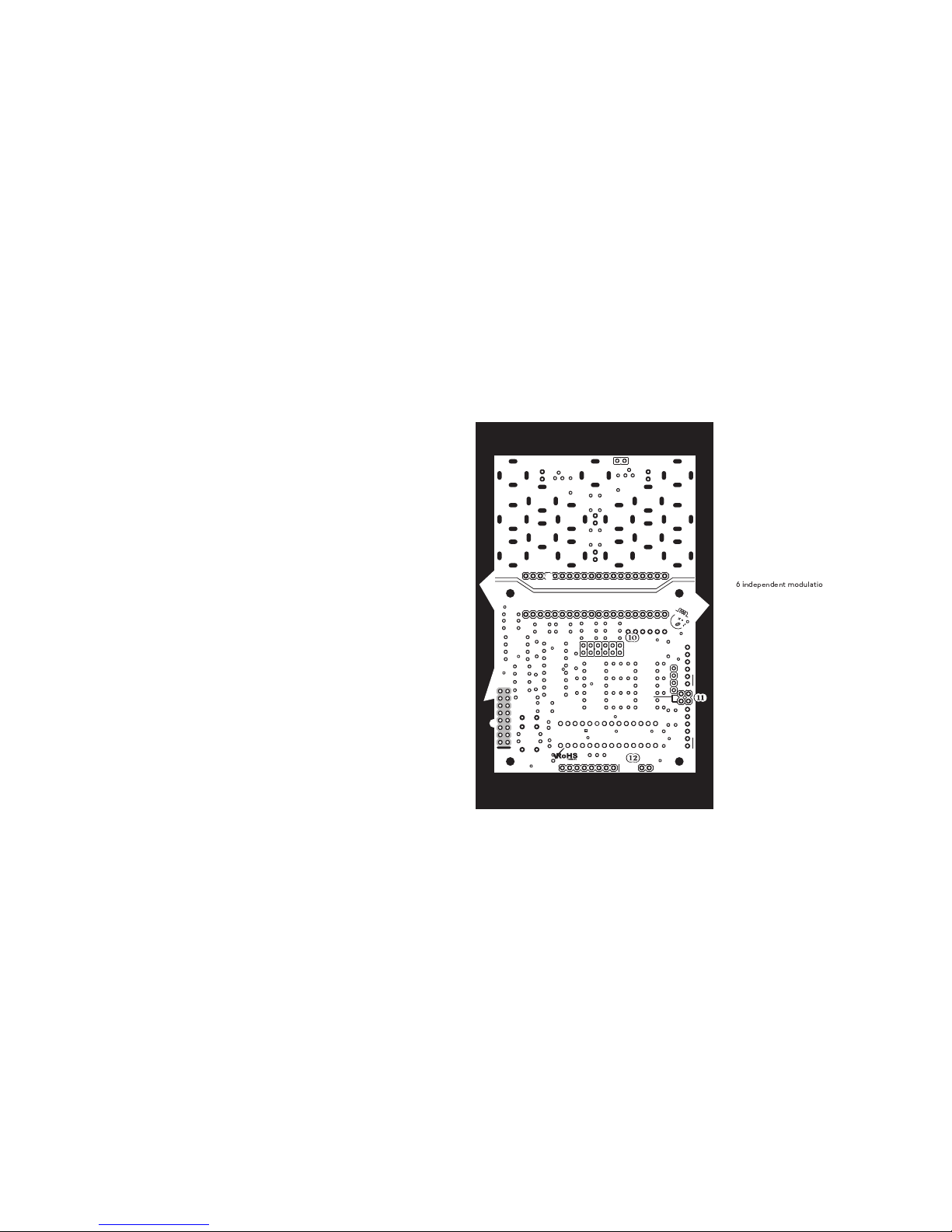
Six jumpers on the bck side of the CV Trinity select
whether the CV input should rect to 0-5V (jumper
inserted) or 0-10V (jumper not inserted). This cn be
setfor ech chnnel individully.
Two jumpers in between the programming headers
assurecommunication between the circuit boards. Both
of them have to be inserted (vertical position) for proper
operation. In case you would like to hack the Trinity or
upgrade the source code you can use the standard FTDi
USB adaptor pin headers for programming the interface
(top) board and the CV (bottom) board. The “disconnect
for programming” jumpers have to be unplugged for
proper upload procedure.
Expansion pin headers are here for connecting expansion
modules. please follow the side marking on the
appropriate expansion boards.
FN
RST
CLOCK RATE
SAV E
CV
GATE IN
C V
O U T
CV TRINITY
RREC
loop
R
R
E
C
O
R
D
G
L
F
O
R
A
T
E
B
A
T
T
A
C
K
R
Q
U
A
N
T
I
Z
E
G
S
H
A
P
E
B
R
E
L
E
A
S
E
R
S
M
O
O
T
H
G
X
O
R
S
H
A
P
E
B
S
U
S
T
A
I
N
R
A
U
T
O
M
A
T
I
O
N
G
L
F
O
B
A
D
S
R
I
II
MODE
SELECT
select OUTclk OUTclk IN
modultion signl source
RCLEAR
GPING
BLOOP
RCLK
GSYNC
BHOLD
RODD
GRANGE
BLINEAR
RihtLeft
To
CV Trinit
HEX MODULATION SIGNAL SUPERHERO
technical details
14HP
35mm deep
PTC fuse nd diode protected 16 pin power connector
requires +5V on bus bord
current consumption: +12V: <5mA, -12V <5mA, +5V: <35mA
Before connectin the ribbon cable to this module
disconnect our sstem from ower !
Double check the olarit of the ribbon cable and
that it is not shifted in an direction. the red cable
should match the -12V rail both on the module and
on the bus board !
lease make sure of the followin
you hve stndrd pinout eurorck bus bord
you hve +5, +12 nd -12 power rils on tht bus
bord
the power rils re not overloded by current
Although we put protection circuits in the device,
we do not tke ny responsibility for dmges
cused by wrong power supply connection.
After you connected everything, double-checked
it nd closed your system, so no power lines cn
be touched by hnd, turn on your system nd test
the module.
!
Connectin module to our sstem
6
tmodultion chnnels
CV input nd CV output per chnnel
select OUT outputs current selected modultion
chnnel
indiction LED for select OUT
ech chnnel cn be either AUTOMATION, LFO or ADSR
AUTOMATION: clocked 32 step memory with djustble
liner interpoltion, number of steps nd possibility of
independent clocking
LFO: rte, XOR wveshpe, shpe (rmp, inverted
rmp, tringle, flopping rmp, flopping tringle, stepped
rndom with smoothing nd looping), synchronistion
with clock
ADSR: ttck, sustin , decy set to sme vlue s
relese, liner or exponentil, looping mode, ttck-hold-
relese mode
jumpers to select 0— 5V or 0—10V rnge for ech CV
input
clock input
clock genertor output normlized to clock input
AUTOMATION
Automtion is 32 step knob recorder with djustble
mount of liner interpoltion. Hold the record button
nd use the TOP knob to enter voltges into the memory.
Pulse signl on Clock input dvnces to next step. The
LEFT knob djusts the mount of smoothing. When it is
fully to the left, the signl is stepped nd when fully right
it is linerly interpolted. The RIGHT knob djusts how
mny of 32 steps re used.
Holding the FN button nd pressing the big SELECT
buttons gives you ccess to more settings. The leftmost
big button sets whether the utomtion is clocked by
themster clock (light ON) or if it is expecting clock
on the selected chnnel input (light OFF). The middle
big button clers the whole memory to 0 volts. The
rightmost big button selects whether the number of
steps set by the RIGHT knob llows ny number including
odd numbers or if it filters them out nd lets you set the
number of steps only to 1,2,4,8,16 or 32 steps.
LFO
LFO is n dvnced low frequency oscilltor with
wveshper nd mny extr fetures including loopble
clocked rndom genertor with smoothing.
In the defult settings, the TOP knob sets the LFO rte.
In synchronistion mode it sets the divider of the clock
input to which the LFO will synchronise nd in pingble
mode it sets the reltive phse shift of the ping input
clock.
The RIGHT knob selects the wveform/ type of the LFO.
In order from leftmost to rightmost the wveforms re:
tringle, sw, rmp, flopping tringle, flopping sw,
stepped rndom, looped stepped rndom. The stepped
rndom mode is either clocked by the LFO rte, or by the
divider of the clock input, when in synchronistion mode.
The looped stepped rndom mode tkes the lst 32 steps
of the stepped rndom pttern nd loops them.
features
The LEFT knob sets wveshping or smoothing for the
stepped rndom wve. For rmp wveform it cts s
bit reducer nd for the stepped rndom wve it works
s smoothing. For ll other wveforms it cts s XOR
modultion. This mens tht the wveform is XORed with
number from 0-255 set by this knob. XORing with 255
inverts the wveform.
Holding the FN button nd pressing the big SELECT
buttons gives you ccess to the following settings.
The leftmost big button sets whether the LFO is free
running (light OFF) or synchronised to the min CLK
IN. When synchronised, the TOP knob sets the divider
specifying how mny clock pulses one LFO period should
lst. The leftmost chnnels synchronize with no phse
offset to the clock, the middle chnnels synchronize with
90°phse shift nd the leftmost chnnels synchronize
with 180°phse shift. This cn be used for vrious
qudrture effects.
The middle big button sets whether the CV input is
ffecting the LFO rte proportionlly with the voltge on
tht input (light OFF) or if it works in pingble mode. This
mens tht if you send t lest two pulses to this input,
the LFO sets its rte to the time in between these pulses.
When this setting is ctivted the synchronistion to the
min clock is dectivted nd the TOP knob ffects the
phse shift reltive to the clock on CV input.
The rightmost big button selects the rnge of the LFO. It cn
be slow with periods in the rnge of 2 min to 200ms (light
off) of fst: 2 s -10 ms. This pplies only to the free running
LFO (both middle nd leftmost lights re turned OFF).
ADSR
ADSR uses the CV input s GATE input for triggering
the envelope. The TOP knob sets ttck (1ms—10s). The
LEFT knob sets sustin or hold time, when in hold mode
(1ms —10s). The RIGHT knob sets both decy nd relese
time (1ms — 10s).
Holding the FN button nd pressing the big SELECT
buttons gives you ccess to more settings. The leftmost
big button cn turn on HOLD mode (light ON). In hold
mode, the envelope is in ttck - hold - relese mode.
Theenvelope resets the full cycle nytime there is rising
edge from clock pulse t the GATE input.
The middle big button sets whether the envelope is in
LOOP mode (light ON). In the this mode, the GATE input
resets the envelope cycle.
The rightmost big button selects whether the envelope
isliner (light ON) or exponentil (light OFF).
Red
Green
Blue
Take it Carefull
CV5 CV2CV3CV6 CV4 CV1
BASTL-INSTRUMENTS.com
designed and produced in czech republic
red
GND +12 +5-12
POWER
jumper = 0-5V range
no jumper = 0-10V range
disconnect for programming
program top
exp D2-prot
program bottom
!
P C B
Table of contents
Other Bastl Music Equipment manuals


