Bauer B-Timer User manual

Filter Cartridge Lifetime Computer
for Filter Systems P21 P31 P41
1
01/2011
Introduction
Read the operating instructions carefully before operating the
unit. (Applicable for units from version 300.301.811 up).
The settings in the setup menu are essential
for the correct indication of the filter capac
ity. Without correct settings, the B-Timer can
be used as an hourmeter, only!
Make sure that the pressure maintaining
valve of the compressor is adjusted to 150 bar
(factory setting) and is working properly to
ensure correct indication of the filter capacity and com
pressor operation recognition.
Make sure that all maintenance counter
(a+b+c) were reset directly before the
delivery. (Otherwise storage times would be
taken into account and wrong maintenance intervals are
displayed on the B-Timer.) If no reset of the maintenance
counters has been done, you are obliged to reset them.
Refer to Reset on page 4.
Description
The B-Timer (Fig. 1) is a self-activating mini-computer that
counts the operating hours of the compressor and calculates
the saturation of the filter cartridge from time, temperature,
cartridge type, and delivery rate of the compressor. It displays
operating hours, cartridge lifetime, and all maintenance due for
the compressor. The B-Timer does neither need external power
nor any other connection to the pressure system. It is simply fas
tened to the filter housing which has to be monitored, by means
of a clamp, and is therefore the ideal filter control device for all
mobile compressor units, especially for portable petrol or diesel
driven scuba diving models. In addition, the B-Timer can be
mounted easily to any unit as an upgrade device.
Authorized use
This unit is to be used exclusively as operating status monitoring
device and does not release the user from additional surveil
lance and testing of the breathing air quality of the filter system
according to national standards (e.g. EN 12021). With the B-
Timer, this is not possible!
The B-Timer may only be used with the filter systems specified
above, it cannot be used on Verticus and Mini-Verticus com
pressor units. The respective filter cartridge numbers are stored
in the software. Other use is strictly prohibited. The manufac
turer and the supplier void all responsibility for risk, damage or
injury resulting from failure to follow these instructions.
Observe the operating limits of the unit:
Operating temperature range 0°C to +50 °C,
Storage temperature -20°C bis +70 °C
Protection class IP65 (Protection against contact with wire, dust,
and jet of water
Vibration $3g in operation
max. 95% humidity, not condensating
Mounting
Mount the B-Timer with the supplied clamp in the center of the
golden filter housing, on P41 filter system at the grey purifier
housing. It has to have contact to the housing with both straps
of the back plate. Make sure not to touch other mounting
clamps of the filter. Should the B-Timer have to be re-mounted,
e.g. when changing the filter housing, ensure that the tempera
ture pad on the back plate is not damaged.
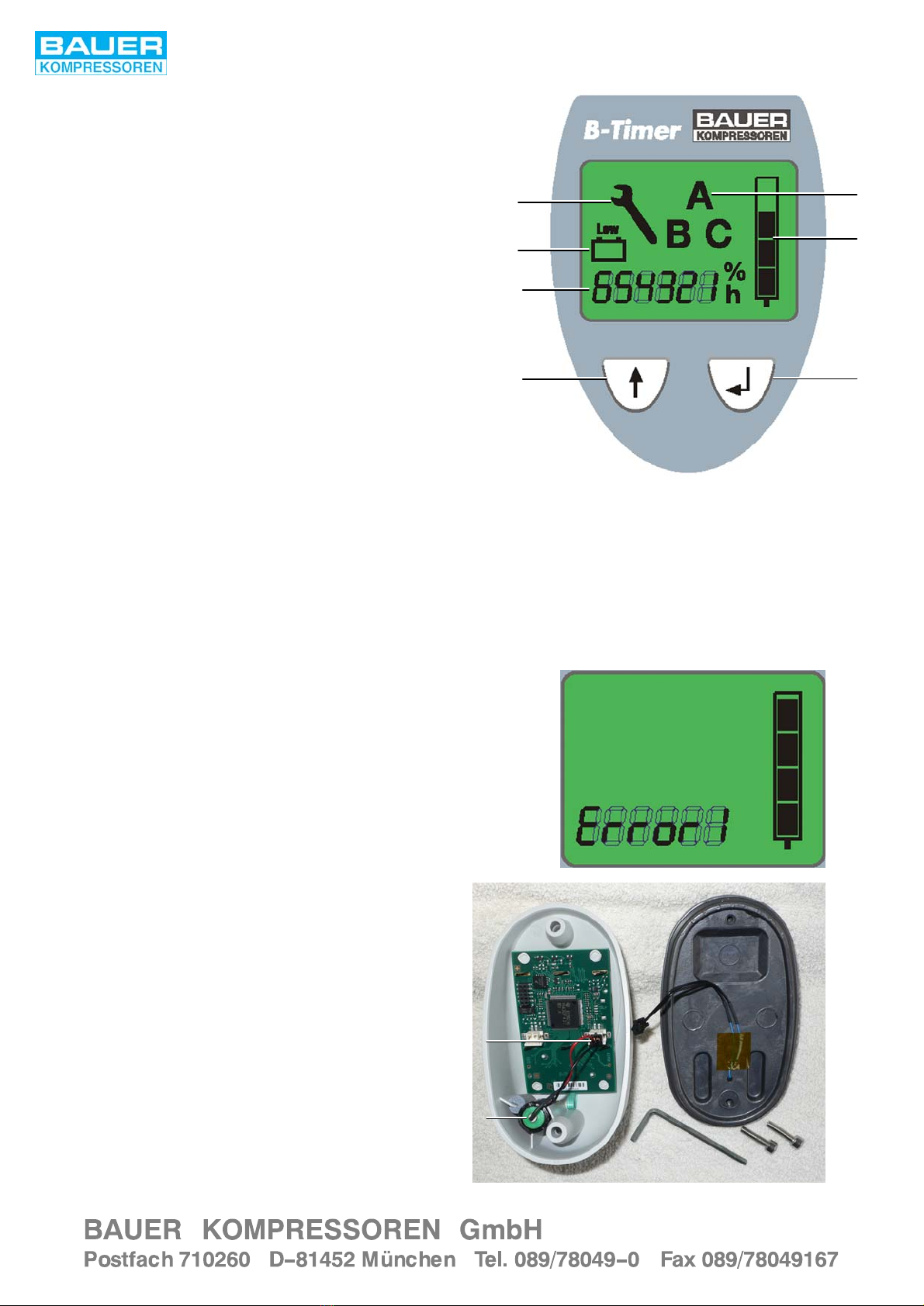
Fig. 1 B-Timer
2
Function
The B-Timer display shows the following functions:
•Operating hours of the compressor unit The flashing h-sym
bol shows that compressor operation has been detected.
•Cartridge lifetime in % by means of four segments in the car
tridge symbol.
•Flashing last segment and change from operating hours in
dication to cartridge part no. if capacity is equal or less than
20% of the original lifetime.
•Indication of compressor maintenance due by means of
letter symbols and operating hours.
A = 500 hours or 1 year
B = 1000 hours or 2 years
C = 2000 hours or 4 years
•Battery symbol indicating that the lithium battery is low and
has to be changed. All data are stored and will not be
lost when changing battery.
The B-Timer is operated using the mode select and the enter
keys.
Error indication
If the temperature sensor in the unit should be defective, an
error message “Error 1” or “Error 2” is shown at the display
(Fig. 3). In this case the unit should not be used but sent to the
factory or the nearest BAUER representative for repair.
Battery change
The battery (1, Fig. 4) is merely inserted into the holder. To
change the battery remove plug (2) and pull out battery. Make
sure to use the same type battery (BAUER part no. 82743).
Fig. 2 Display
12
34
5
6 7
1 Key symbol (maintenance due)
2 Letter symbol (maintenance type)
3 Low battery symbol
4 Cartridge saturation indicator
5 Operating hours or cartridge number
6 Mode select key
7 Enter key
Fig. 3
Fig. 4 Battery
1
2

3
01/2011
Operation
The B-Timer is activated when starting the
compressor. Compressor operation is indi
cated by the flashing “h” symbol.
To switch on the B-Timer press one of the keys on the display.
Main menue will be displayed (Fig. 5).
If no key is pressed within 1 minute, the in
dication will return to the main menue. After
2 minutes the B-Timer is switched off, if no
compressor operation is detected.
Function Display
To display the desired function, press the se
lect key ().
Press key. Remaining filter capacity is shown, Fig. 6)
Press key again. Remaining operating hours to service interval
A (500 hours or annually) are shown (Fig. 7).
Press key again. Remaining operating hours to service interval
B (1000 hours or annually) are shown (Fig. 8).
Press key again. Remaining operating hours to service interval
C (2000 hours or biennially) are shown (Fig. 9).
Fig. 5
Fig. 6
Fig. 7
Fig. 8
Fig. 9
4
Press key. Filter cartrige number is shown (Filter symbol flash
ing, Fig. 10).
Press key again. Display returns to the main menue.
Reset
The filter capacity must not be reset unless a
new filter cartridge has been fitted!
To reset the filter capacity or the A, B, and C maintenance inter
vals, press key for more than 5 seconds from the respective
maintenance interval display (Fig. 11).
Setup
To enter the setup for the different functions of the B-Timer
press the and keys on the display simultaneously for more
than 5 seconds from the cartridge number display (Fig. 10).
Filter symbol starts flashing (Fig. 12) indicating the setup mode.
Under setup A the filter cartridge number is set. To change car
tridge type, press key for 3 seconds, the number starts flash
ing. Press the key to select the correct number, press key to
accept the new setting.
Numbers beginning with 999 require a
special adjustment:
Press key for 3 seconds. Press the key to select 999000, the
last 0 starts flashing. Press the key to select the correct
number, then press key: the second 0 will start flashing, pro
ceed as above and finally adjust the 3rd 0 accordingly.
Pressing the key, display changes to setup B for the delivery
setting (in ltrs/min). Filter symbol starts flashing (Fig. 13). To
change delivery, press key for 3 seconds, the 1st digit starts
flashing. Press the key to select the correct number, press
key to accept the new setting. Repeat procedure for the other
two digits
Pressing the key again, display changes to setup C for the
pressure range setting. Filter symbol starts flashing (Fig. 14). To
change pressure, press key for 3 seconds. Press the key to
select the correct pressure (200, 300 or 200/300), press key
to accept the new setting.
After finishing setup and fitting a new car
tridge, the filter capacity has absolutely to be
reset, see “Reset” above.
Pressing the key again, display changes to the menue for ad
justing the operating hours. Press key for 2 seconds, the last
digit will start flashing. Press the key to select the correct
number, then press key etc., until all digits are set. Then pres
sing the key twice will lead back to the main menue, Pressing
the the key and the key gives the possibility to readjust the
hours again, if required.
Fig. 10
Fig. 11
Fig. 12
Fig. 13
Fig. 14


