Baum HOG 75 K User manual

MB046 - 11055649 Baumer_HOG75K_II_DE-EN (14A1)
HOG 75 K • HOG 75 KC
Inkrementaler Drehgeber
Incremental Encoder
Montage- und Betriebsanleitung
Installation and operating instructions

Baumer_HOG75K_II_DE-EN (14A1) MB046 - 11055649
Inhaltsverzeichnis
Inhaltsverzeichnis
1Allgemeine Hinweise ...................................................................................................................................................1
2Betrieb in explosionsgefährdeten Bereichen .............................................................................................3
3Sicherheitshinweise .....................................................................................................................................................5
4Vorbereitung ......................................................................................................................................................................7
4.1 Lieferumfang ........................................................................................................................................................7
4.2 Zur Montage erforderlich bzw. empfohlen (nicht im Lieferumfang enthalten) ...................8
4.3 Zur Demontage erforderlich (nicht im Lieferumfang enthalten) ................................................9
4.4 Erforderliches Werkzeug (nicht im Lieferumfang enthalten) .......................................................9
5Montage ............................................................................................................................................................................. 10
5.1 Schritt 1 ................................................................................................................................................................ 10
5.2 Schritt 2 ................................................................................................................................................................ 10
5.3 Schritt 3 .................................................................................................................................................................11
5.4 Schritt 4 ................................................................................................................................................................ 12
5.5 Schritt 5 - Drehmomentstütze .................................................................................................................. 13
5.6 Hinweis zur Vermeidung von Messfehlern ........................................................................................ 14
5.7 Schritt 6 ................................................................................................................................................................ 15
5.8 Schritt 7 ................................................................................................................................................................ 15
5.9 Schritt 8 ................................................................................................................................................................ 16
5.10 Anbauhinweis .................................................................................................................................................... 16
6Abmessung ......................................................................................................................................................................17
7Elektrischer Anschluss .......................................................................................................................................... 18
7.1 Klemmenbelegung ......................................................................................................................................... 18
7.2 Ausgangssignale ............................................................................................................................................. 18
7.3 Sensorkabel HEK 8 (Zubehör) ................................................................................................................. 19
8Demontage ...................................................................................................................................................................... 20
8.1 Schritt 1 und 2 .................................................................................................................................................. 20
8.2 Schritt 3 ................................................................................................................................................................ 21
8.3 Schritt 4 ................................................................................................................................................................ 21
8.4 Schritt 5 ................................................................................................................................................................ 22
8.5 Schritt 6 ................................................................................................................................................................ 22
8.6 Schritt 7 ................................................................................................................................................................ 22
9Technische Daten ....................................................................................................................................................... 23
9.1 Technische Daten - elektrisch .................................................................................................................. 23
9.2 Technische Daten - mechanisch ............................................................................................................ 23
10 Anhang: EU-Konformitätserklärung .............................................................................................................. 25
11 Zubehör .............................................................................................................................................................................. 26

MB046 - 11055649 Baumer_HOG75K_II_DE-EN (14A1)
Table of contents
Table of contents
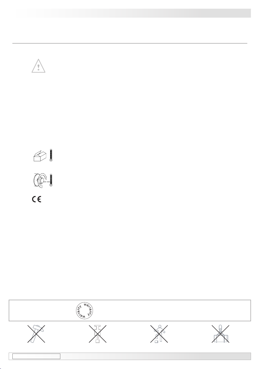
1General notes ...................................................................................................................................................................2
2Operation in potentially explosive environments ....................................................................................4
3Security indications .....................................................................................................................................................6
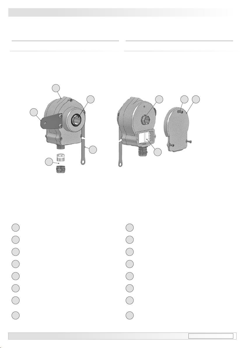
4Preparation .........................................................................................................................................................................7
4.1 Scope of delivery ...............................................................................................................................................7
4.2 Required resp. recommended for mounting (not included in scope of delivery) .............. 8
4.3 Required for dismounting (not included in scope of delivery) ....................................................9
4.4 Required tools (not included in scope of delivery) ...........................................................................9
5Mounting ........................................................................................................................................................................... 10
5.1 Step 1 .................................................................................................................................................................... 10
5.2 Step 2 .................................................................................................................................................................... 10
5.3 Step 3 .....................................................................................................................................................................11
5.4 Step 4 .................................................................................................................................................................... 12
5.5 Step 5 - Torque arm ....................................................................................................................................... 13
5.6 How to prevent measurement errors .................................................................................................... 14
5.7 Step 6 .................................................................................................................................................................... 15
5.8 Step 7 .................................................................................................................................................................... 15
5.9 Step 8 .................................................................................................................................................................... 16
5.10 Mounting instruction ...................................................................................................................................... 16
6Dimension ........................................................................................................................................................................ 17
7Electrical connection ................................................................................................................................................ 18
7.1 Terminal assignment ..................................................................................................................................... 18
7.2 Output signals ................................................................................................................................................... 18
7.3 Sensor cable HEK 8 (accessory) ........................................................................................................... 19
8Dismounting ................................................................................................................................................................... 20
8.1 Step 1 and 2 ...................................................................................................................................................... 20
8.2 Step 3 .................................................................................................................................................................... 21
8.3 Step 4 .................................................................................................................................................................... 21
8.4 Step 5 .................................................................................................................................................................... 22
8.5 Step 6 .................................................................................................................................................................... 22
8.6 Step 7 .................................................................................................................................................................... 22
9Technical data ............................................................................................................................................................... 24
9.1 Technical data - electrical ratings ........................................................................................................... 24
9.2 Technical data - mechanical design ...................................................................................................... 24
10 Appendix: EU Declaration of conformity .................................................................................................... 25
11 Accessories .................................................................................................................................................................... 26

1 Baumer_HOG75K_II_DE-EN (14A1) MB046 - 11055649
1Allgemeine Hinweise
Achtung!
Beschädigung des auf dem Gerät bendlichen Siegels führt zu Gewährleistungsverlust.
1Allgemeine Hinweise
1.1 Zeichenerklärung:
Gefahr
Warnung bei möglichen Gefahren
Hinweis zur Beachtung
Hinweis zur Gewährleistung eines einwandfreien Betriebes des Produkts
i
Information
Empfehlung für die Produkthandhabung
1.2
Der
inkrementale
Drehgeber HOG 75 K(C) ist ein opto-elektronisches Präzisionsmessgerät, das
mit Sorgfalt nur von technisch qualiziertem Per sonal gehandhabt werden darf.
1.3 Die zu erwartende Lebensdauer des Gerätes hängt von den Kugellagern ab, die mit einer
Dauerschmierung ausgestattet sind.
1.4 Der Lagertemperaturbereich des Gerätes liegt zwischen -15 °C bis +70 °C.
1.5 Der Betriebstemperaturbereich des Gerätes liegt zwischen -30 °C bis +85 °C
(eingeschränkt im Ex-Bereich, siehe Abschnitt 2),
am Gehäuse gemessen.
1.6 EU-Konformitätserklärung gemäß den europäischen Richtlinien.
1.7 Das Gerät ist zugelassen nach UL (gilt nicht für Einsatz in explosionsgefährdeten Bereichen).
1.8 Wir gewähren 2 Jahre Gewährleistung im Rahmen der Bedingungen des Zentralverbandes der
Elektroindustrie (ZVEI).
1.9
Der Drehgeber darf nur wie in dieser Anleitung beschrieben geöffnet werden. Reparaturen oder
Wartungsarbeiten, die ein vollständiges Öffnen des Drehgebers erfordern, sind vom Hersteller
durchzuführen. Am Gerät dürfen keine Veränderungen vorgenommen werden.
1.10 Bei Rückfragen bzw. Nachlieferungen sind die auf dem Typenschild des Gerätes angege-
benen Daten, insbesondere Typ und Seriennummer, unbedingt anzugeben.
1.11 Alle Bestandteile des Drehgebers sind nach länderspezischen Vorschriften zu entsorgen.
i

MB046 - 11055649 Baumer_HOG75K_II_DE-EN (14A1) 2
General notes 1
1General notes
1.1 Symbol guide:
Danger
Warnings of possible danger
General information for attention
Informations to ensure correct product operation
i
Information
Recommendation for product handling
1.2 The incremental encoder HOG 75 K(C) is an opto electronic precision measurement device
which must be handled with care by skilled personnel only.
1.3 The expected operating life of the device depends on the ball bearings, which are equipped with
a permanent lubrication.
1.4 The storage temperature range of the device is between -15 °C and +70 °C.
1.5 The operating temperature range of the device is between -30 °C and +85 °C
(restricted in potentially explosive environments, see section 2),
measured at the housing.
1.6 EU-Declaration of Conformity meeting to the European Council Directives.
1.7 The device is UL approved (not applicable for operation in potentially explosive atmospheres).
1.8 We grant a 2-year warranty in accordance with the regulations of the ZVEI (Central Association
of the German Electrical Industry).
1.9 The encoder may be only opened as described in this instruction. Repair or mainte-
nance work that requires opening the encoder completely must be carried out by the
manufacturer. Alterations of the device are not permitted.
1.10 In the event of queries or subsequent deliveries, the data on the device type label must be
quoted, especially the type designation and the serial number.
1.11 Encoder components are to be disposed of according to the regulations prevailing in the re-
spective country.
Warning!
Damaging the seal on the device invalidates warranty.
i

3 Baumer_HOG75K_II_DE-EN (14A1) MB046 - 11055649
2Betrieb in explosionsgefährdeten Bereichen
Das Gerät entspricht der Norm EG-Richtlinie 94/9/EG für
explosionsgefährdete Bereiche.
Der Einsatz ist gemäß den
Gerätekategorien 3 G (Ex-Atmosphäre Gas) und 3D(Ex-Atmosphäre
Staub) zulässig.
Gerätekategorie 3 G: - Ex-Kennzeichnung: II 3 G Ex nA IIC T4 Gc
- Normenkonformität: EN 60079-0:2009
EN 60079-15:2010
- Zündschutzart: nA
- Temperaturklasse: T4
- Gerätegruppe: II
Gerätekategorie 3 D: - Ex-Kennzeichnung: II 3 D Ex tc IIIB T85°C Dc
- Normenkonformität: EN 60079-31:2009
- Schutzprinzip: Schutz durch Gehäuse
- Max. Oberächentemperatur: +85 °C
- Gerätegruppe: III
Der Einsatz in anderen explosionsgefährdeten Bereichen ist nicht zulässig.
2.1 Der maximale Umgebungstemperaturbereich für den Einsatz des Gerätes im Ex-Bereich
beträgt -20 °C bis +40 °C.
2.2 Der Anlagenbetreiber hat zu gewährleisten, dass eine mögliche Staubablagerung eine maxi-
male Schichtdicke von 5 mm nicht überschreitet (gemäß EN 60079-14).
2.3 Eine gegebenenfalls an anderen Stellen aufgeführte UL-Listung gilt nicht für den Einsatz im
Ex-Bereich.
2.4 Das Gerät darf nur in Betrieb genommen werden, wenn ...
– die Angaben auf dem Typenschild des Gerätes mit dem zulässigen Ex-Einsatzbereich vor
Ort übereinstimmen (Gerätegruppe, Kategorie, Zone, Temperaturklasse bzw. maximale
Oberächentemperatur),
– die Angaben auf dem Typenschild des Gerätes mit dem Spannungsnetz übereinstimmen,
– das Gerät unbeschädigt ist (keine Schäden durch Transport und Lagerung) und
– sichergestellt ist, dass keine explosionsfähige Atmosphäre, Öle, Säure, Gase, Dämpfe,
Strahlungen etc. bei der Montage vorhanden sind.
2.5 An Betriebsmitteln, die in explosionsgefährdeten Bereichen eingesetzt werden, darf keine
Veränderung vorgenommen werden. Reparaturen dürfen nur durch vom Hersteller autorisierte
Stellen ausgeführt werden. Bei Zuwiderhandlung erlischt die Ex-Zulassung.
2.6 Bei der Montage und Inbetriebnahme ist die Norm EN 60079-14 zu beachten.
2Betrieb in explosionsgefährdeten Bereichen
Das Gerät ist entsprechend den Angaben in der Montage- und Betriebsanleitung zu be-
treiben. Die für die Verwendung bzw. den geplanten Einsatzzweck zutreffenden Gesetze,
Richtlinien und Normen sind zu beachten.

MB046 - 11055649 Baumer_HOG75K_II_DE-EN (14A1) 4
2Operation in potentially explosive environments
The device complies with the EU standard 94/9/EG for potentionally explosive atmospheres.
It can be used in accordance with equipment categories 3 G (explosive gas atmosphere) and
3 D (explosive dust atmosphere).
Equipment category 3 G: - Ex labeling: II 3 G Ex nA IIC T4 Gc
- Conforms to standard: EN 60079-0:2009
EN 60079-15:2010
- Type of protection: nA
- Temperature class: T4
- Group of equipment: II
Equipment category 3 D: - Ex labeling: II 3 D Ex tc IIIB T85°C Dc
- Conforms to standard: EN 60079-31:2009
- Protective principle: Protection by enclosure
- Max. surface temperature: +85 °C
- Group of equipment: III
The operation in other explosive atmospheres is not permissible.
2.1 In Ex areas the device must only be used within the ambient temperature range from -20 °C to
+40 °C.
2.2 The plant operator must ensure that any possible dust deposit does not exceed a thickness of
5 mm (in accordance with EN 60079-14).
2.3 An UL listing that may be stated elsewhere is not valid for use in explosive environ-
ments.
2.4 Operation of the device is only permissible when ...
– the details on the type label of the device match the on-site conditions for the permissible
Ex area in use (group of equipment, equipment category, zone, temperature class or maxi-
mum surface temperature),
– the details on the type label of the device match the electrical supply network,
– the device is undamaged (no damage resulting from transport or storage), and
– it has been checked that there is no explosive atmosphere, oils, acids, gases, vapors,
radiation etc. present during installation.
2.5 It is not permissible to make any alteration to equipment that is used in potentially explosive envi-
ronments. Repairs may only be carried out by authorized authorities provided by the manufacturer.
Contravention invalidates the EX approval.
2.6 Attend the norm EN 60079-14 during mount and operation.
Operation in potentially explosive environments 2
The device must be operated in accordance with the stipulations of the installation and
operating instructions. The relevant laws, regulations and standards for the planned ap-
plication must be observed.

5 Baumer_HOG75K_II_DE-EN (14A1) MB046 - 11055649
3Sicherheitshinweise
3.1 Verletzungsgefahr durch rotierende Wellen
Haare und Kleidungsstücke können von rotierenden Wellen erfasst werden.
•Vor allen Arbeiten alle Betriebsspannungen ausschalten und Maschinen stillsetzen.
3.2 Zerstörungsgefahr durch elektrostatische Auadung
Die elektronischen Bauteile im Drehgeber sind empndlich gegen hohe Spannungen.
•Steckkontakte und elektronische Komponenten nicht berühren.
•Ausgangsklemmen vor Fremdspannungen schützen.
•Max. Betriebsspannung nicht überschreiten.
3.3 Zerstörungsgefahr durch mechanische Überlastung
Eine starre Befestigung kann zu Überlastung durch Zwangskräfte führen.
•Die Beweglichkeit des Drehgebers niemals einschränken. Unbedingt die Montagehinweise
beachten.
•Die vorgegebenen Abstände und/oder Winkel unbedingt einhalten.
3.4 Zerstörungsgefahr durch mechanischen Schock
Starke Erschütterungen, z. B. Hammerschläge, können zur Zerstörung der Abtastung führen.
•Niemals Gewalt anwenden. Bei sachgemäßer Montage lässt sich alles leichtgängig zusam-
menfügen.
•Für die Demontage geeignetes Abziehwerkzeug benutzen.
3.5 Zerstörungsgefahr durch Verschmutzung
Schmutz kann im Drehgeber zu Kurzschlüssen und zur Beschädigung der optischen Abtastung
führen.
•Während aller Arbeiten am geöffneten Klemmenkasten auf absolute Sauberkeit achten.
•Bei der Demontage niemals Öl oder Fett in das Innere des Drehgebers gelangen lassen.
3.6 Zerstörungsgefahr durch klebende Flüssigkeiten
Klebende Flüssigkeiten können die optische Abtastung und die Lager beschädigen. Die Demon-
tage eines mit der Achse verklebten Drehgebers kann zu dessen Zerstörung führen.
3.7 Explosionsgefahr
Der Drehgeber darf in explosiongefährdeten Bereichen der Kategorien 3 D und 3 G eingesetzt
werden. Der Betrieb in anderen explosionsgefährdeten Bereichen ist nicht zulässig.

MB046 - 11055649 Baumer_HOG75K_II_DE-EN (14A1) 6
Security indications 3
3Security indications
3.1 Risk of injury due to rotating shafts
Hair and clothes may become tangled in rotating shafts.
• Before all work switch off all operating voltages and ensure machinery is stationary.
3.2 Risk of destruction due to electrostatic charge
Electronic parts contained in the encoder are sensitive to high voltages.
• Do not touch plug contacts or electronic components.
• Protect output terminals against external voltages.
• Do not exceed max. operating voltage.
3.3 Risk of destruction due to mechanical overload
Rigid mounting may give rise to constraining forces.
• Never restrict the freedom of movement of the encoder. The installation instructions must be
followed.
• It is essential that the specied clearances and/or angles are observed.
3.4 Risk of destruction due to mechanical shock
Violent shocks, e. g. due to hammer impacts, can lead to the destruction of the optical sensing system.
• Never use force. Assembly is simple when correct procedure is followed.
• Use suitable puller for disassembly.
3.5 Risk of destruction due to contamination
Dirt penetrating inside the encoder can cause short circuits and damage the optical sensing sys-
tem.
• Absolute cleanliness must be maintained when carrying out any work on the open terminal box.
• When dismantling, never allow lubricants to penetrate the encoder.
3.6 Risk of destruction due to adhesive uids
Adhesive uids can damage the optical sensing system and the bearings. Dismounting an en-
coder, secured to a shaft by adhesive may lead to the destruction of the unit.
3.7 Explosion risk
You can use the encoder in areas with explosive atmospheres of category 3 D and 3 G. The opera-
tion in other explosive atmospheres is not permissible.

7 Baumer_HOG75K_II_DE-EN (14A1) MB046 - 11055649
4Vorbereitung / Preparation
1Gehäuse
2Konuswelle mit Schlüsseläche SW 17 mm
3Stützblech für Drehmomentstütze
4Abdeckhaube
5Torx-Schraube M3x12 mm
6Erdungsband ~195 mm lang
7Kabelverschraubung M16x1,5
für Kabel ø5-9 mm
8Anschlussklemmen, siehe Abschnitt 7.1.
1Housing
2Cone shaft with spanner at 17 mm a/f
3Support plate for torque arm
4Cover
5Screw with torx drive M3x12 mm
6Earthing strap, length ~195 mm
7Cable gland M16x1.5
for cable ø5-9 mm
8Connecting terminal, see section 7.1.
4Vorbereitung
4.1 Lieferumfang
4Preparation
4.1 Scope of delivery
1
2 2 45
3
68
7

MB046 - 11055649 Baumer_HOG75K_II_DE-EN (14A1) 8
Vorbereitung / Preparation 4
4.2
Zur Montage erforderlich bzw. empfohlen
(nicht im Lieferumfang enthalten)
4.2
Required resp. recommended for mounting
(not included in scope of delivery)
9
11a 11e 11d 11b 11c
12a
15
12b
14 13
10
3x
3x
11 12
L
9Drehmomentstütze, als Zubehör erhältlich,
Bestellnummer (Länge L, Version):
11043628 (67-70 mm, Standard)
11004078 (125 (±5) mm, Standard,
kürzbar auf ≥71 mm)
11083179 (440 (+20/-15) mm, Standard,
kürzbar auf ≥131 mm)
11054917 (67-70 mm, isoliert)
11072795 (125 (±5) mm, isoliert,
kürzbar auf ≥71 mm)
11082677 (440 (+20/-15) mm, isoliert,
kürzbar auf ≥131 mm)
11054918 (67-70 mm, rostfreier Stahl)
11072787 (125 (±5) mm, rostfreier Stahl,
kürzbar auf ≥71 mm)
11072737 (440 (+20/-15) mm,
rostfreier Stahl,
kürzbar auf ≥131 mm)
10 Sensorkabel HEK 8,
als Zubehör erhältlich, siehe Abschnitt 6.3.
11 Montageset als Zubehör erhältlich,
Bestellnummer 11077197, bestehend aus:
11a
Gewindestange M6 (1.4104), Länge variabel
(≤210 mm)
11b
Scheibe B6,4, ISO 7090 (A2)
11c
Selbstsichernde Mutter M6, ISO 10511 (A2)
11d
Zylinderschraube M6x8, ISO 1207 (Ms)
für Erdungsband
11e
Scheibe B6,4, ISO 7090 (Ms)
für Erdungsband
12
Montage-/Demontageset als Zubehör erhältlich,
Bestellnummer 11077087, bestehend aus:
12a
Federring 6, DIN 7980
12b
Zylinderschraube M6x30, ISO 4762 (A2)
13
Sechskantschraube M6x18 mm, ISO 4017 (A2)
14 Scheibe B6,4, ISO 7090 (A2)
15 Selbstsichernde Mutter M6, ISO 10511 (A2)
9Torque arm, available as accessory,
order number (length L, version):
11043628 (67-70 mm, standard)
11004078 (125 (±5) mm, standard,
can be shortened to ≥71 mm)
11083179 (440 (+20/-15) mm, standard,
can be shortened to ≥131 mm)
11054917 (67-70 mm, insulated)
11072795 (125 (±5) mm, insulated,
can be shortened to ≥71 mm)
11082677 (440 (+20/-15) mm, insulated,
can be shortened to ≥131 mm)
11054918 (67-70 mm, stainless steel)
11072787 (125 (±5) mm, stainless steel)
can be shortened to ≥71 mm)
11072737 (440 (+20/-15) mm,
stainless steel,
can be shortened to ≥131 mm)
10 Sensor cable HEK 8,
available as accessory, see section 6.3.
11 Mounting kit available as accessory,
order number 11077197, including:
11a
Thread rod M6 (1.4104), length variabel
(≤210 mm)
11b
Washer B6.4, ISO 7090 (A2)
11c
Self-locking nut M6, ISO 10511 (A2)
11d
Cylinder screw M6x8, ISO 1207 (Ms)
for earthing strap
11e
Washer B6.4, ISO 7090 (Ms)
for earthing strap
12
Mounting/dismounting kit available as accessory,
order number 11077087, including:
12a
Spring washer 6, DIN 7980
12b
Cylinder screw M6x30, ISO 4762 (A2)
13 Hexagon screw M6x18 mm, ISO 4017 (A2)
14 Washer B6.4, ISO 7090 (A2)
15 Self-locking nut M6, ISO 10511 (A2)

9 Baumer_HOG75K_II_DE-EN (14A1) MB046 - 11055649
4Vorbereitung / Preparation
12
Montage-/Demontageset als Zubehör erhältlich,
Bestellnummer 11077087, bestehend aus:
12c
Gewindestift M6x10, ISO 7436 (5,8 Vzk)
12d
Abdrückschraube M8x45, ISO 4762 (A2)
12
Mounting/dismounting kit available as accessory,
order number 11077087, including:
12c
Setscrew M6x10, ISO 7436 (5.8 Vzk)
12d
Jack screw M8x45, ISO 4762 (A2)
4.3 Zur Demontage erforderlich
(nicht im Lieferumfang enthalten)
4.3 Required for dismounting
(not included in scope of delivery)
4.4 Erforderliches Werkzeug
(nicht im Lieferumfang enthalten)
4.4 Required tools
(not included in scope of delivery)
12
12c 12d
16 Werkzeugset als Zubehör erhältlich,
Bestellnummer: 11068265 16 Tool kit available as accessory,
order number: 11068265
5 und 6 mm
1,6x8,0 mm und 0,8x4 mm
10 (2x) und 17 mm
TX 10
5 und 6 mm
1.6x8.0 mm and 0.8x4 mm
10 (2x), and 17 mm
TX 10

MB046 - 11055649 Baumer_HOG75K_II_DE-EN (14A1) 10
Montage / Mounting 5
5.2 Schritt 2 5.2 Step 2
5Montage
5.1 Schritt 1
5Mounting
5.1 Step 1
9*
15 14 ** *
45 **
* Siehe Seite 7 oder 8
See page 7 or 8
13
10 mm
10 mm
TX 10

5Montage / Mounting
11 Baumer_HOG75K_II_DE-EN (14A1) MB046 - 11055649
5.3
Schritt 3
5.3 Step 3
20 mm
1:10
Zentrierbohrung
Center hole
DIN 332-D, M6x16 mm
ø17JS8 mm
Motorwelle einfetten! Lubricate motor shaft!
Die Antriebswelle sollte einen mög-
lichst kleinen Rundlauffehler auf-
weisen, da dieser zu einem Winkel-
fehler führen kann (siehe Abschnitt
5.6). Außerdem verursachen Rund-
lauffehler Vibrationen, die die Le-
bensdauer des Drehgebers verkür-
zen können.
The drive shaft should have as less
runout as possible because this
can otherwise result in an angle
error (see section 5.6). In addition,
any radial deviation can cause vi-
brations, which can shorten the
lifetime of the encoder.

MB046 - 11055649 Baumer_HOG75K_II_DE-EN (14A1) 12
Montage / Mounting 5
5.4 Schritt 4 5.4 Step 4
Zul. Anzugsmoment:
Max. tightening torque:
Mt= 3-4 Nm
12b12a
11a
11e 11d
11b 11b21b
11c11b
9
**
*
* *
* **
**
*
11c
*
* Siehe Seite 7 oder 8
See page 7 or 8
6*
17 mm
5 mm
10 mm
1.6x8 mm

5Montage / Mounting
13 Baumer_HOG75K_II_DE-EN (14A1) MB046 - 11055649
5.5 Schritt 5 - Drehmomentstütze 5.5 Step 5 - Torque arm
15°
15°
9°
9°
9°
9°
L1
L2 (≥L1)
Die Montage der Drehmomentstütze sollte
spielfrei erfolgen. Ein Spiel von beispiels-
weise ±0,03 mm entspricht einem Rund-
lauffehler des Drehgebers von 0,06 mm,
was zu einem großen Winkelfehler führen
kann (siehe Abschnitt 5.6).
The torque arm should be mounted
free from clearance. A play of just
±0.03 mm, results in concentricity
error of the encoder of 0.06 mm.
That may lead to a large angle error
(see section 5.6).

MB046 - 11055649 Baumer_HOG75K_II_DE-EN (14A1) 14
Montage / Mounting 5
5.6
Hinweis zur Vermeidung von Messfehlern
Für einen einwandfreien Betrieb des
Drehgebers ist ein korrekter Anbau, ins-
besondere auch der Drehmomentstütze,
notwendig, wie beschrieben in Abschnitt
5.1 bis 5.5.
Die Rundlaufabweichung der Motorwelle
sollte möglichst nicht mehr als 0,2 mm
(0,03 mm empfohlen) betragen, da hier-
durch Winkelfehler verursacht werden.
Solche Winkelfehler können durch einen
größeren Abstand L1 reduziert werden1).
Dabei ist zu beachten, dass die Länge L2
der Drehmomentstütze (siehe Abschnitt
5.5) mindestens gleich L1 sein sollte2).
Der Winkelfehler kann wie folgt berechnet
werden:
Δρmech = ± 90°/π· R/L1
mit R: Rundlaufabweichung in mm
L1: Abstand der Drehmomentstütze
zum Drehgebermittelpunkt in mm
Berechnungsbeispiel:
Für R= 0,06 mm und L1 = 69,5 mm ergibt
sich ein Winkelfehler Δρmech von ± 0,025°.
1) Auf Anfrage sind hierzu verschiedene Befes-
tigungsbleche für die Stützen erhältlich.
2) wenn L2 < L1 muss mit der Länge L2 gerechnet
werden
Weitere Informationen erhalten Sie
unter der Telefon-Hotline
+49 (0)30 69003-111
i
5.6
How to prevent measurement errors
To ensure that the encoder operates cor-
rectly, it is necessary to mount it accurately
as described in section 5.1 to 5.5, which in-
cludes correct mounting of the torque arm.
The radial runout of the motor shaft
should not exceed 0.2 mm (0.03 mm
recommended), if at all possible, to prevent
an angle error.
An angle error may be reduced by in-
creasing the length of L11). Make sure
that the length L2 of the torque arm
(see section 5.5) is at least equal to L12).
The angle error can be calculated as fol-
lows:
Δρmech = ± 90°/π· R/L1
with R: Radial run-out in mm
L1: Distance of the torque arm to the
center point of the encoder in mm
Example:
For R= 0.06 mm and L1 = 69.5 mm the re-
sulting angle error Δρmech equals ± 0.025°.
1) For this different braces for the torque arm are
available on request.
2) If L2 < L1, L2 must be used in the calculation
formula
For more information,
call the telephone hotline at
+49 (0)30 69003-111
i

5Montage / Mounting
15 Baumer_HOG75K_II_DE-EN (14A1) MB046 - 11055649
5.7 Schritt 6
5.8 Schritt 7
5.7 Step 6
5.8 Step 7
Zur Gewährleistung der angege-
benen Schutzart sind nur geeignete
Kabeldurchmesser zu verwenden.
To ensure the specied protection
of the device the correct cable dia-
meter must be used.
7*
Ansicht X
siehe Abschnitt 7.1.
View X
see section 7.1.
ø5-9 mm
Kabelschirm
Cable shield
* Siehe Seite 7
See page 7
17 mm
10 *
8*

MB046 - 11055649 Baumer_HOG75K_II_DE-EN (14A1) 16
Montage / Mounting 5
5.10 Anbauhinweis 5.10 Mounting instruction
5.9 Schritt 8 5.9 Step 8
* Siehe Seite 7
See page 7
5*
4*
TX 10
Wir empfehlen, den Drehgeber so
zu montieren, dass der Kabelan-
schluss keinem direkten Was-
sereintritt ausgesetzt ist.
i
i
It is recommended to mount the
encoder with cable connection fa-
cing downward and being not ex-
posed to water.

17 Baumer_HOG75K_II_DE-EN (14A1) MB046 - 11055649
6Abmessung
(73278, 73286)
6Dimension
(73278, 73286)
All dimensions in millimeters (unless otherwise stated)
6Abmessung / Dimension
Positive Drehrichtung
Positive rotating direction
Zubehör
Accessory
17
This manual suits for next models
2
Table of contents
Popular Media Converter manuals by other brands

Keysight Technologies
Keysight Technologies M9403A User's and service guide

Imagine communications
Imagine communications Selenio 6800 HUC6800+C Installation and operation manual

IMC Networks
IMC Networks McPC TP/BNC supplementary guide

Apogee
Apogee AD-8000 datasheet

Blonder tongue
Blonder tongue NXG-SDI4 user manual

PR electronics
PR electronics 9116 Series manual