Baumax RMD650 User manual

Operator’s Manual
Track Dumper RMD650 / RMD650-B
Do not use this device until you have fully read and
understood these instructions!
www.geargb.co.uk [email protected]
28

Do not use this equipment if you are under the influence of drugs, alcohol
or any kind of medication that can affect your reactions.
Table of Contents
Chapter
1. Introduction
2. Safety
3. Hazards, risks & behaviours
4. Operator requirements
5. Applications
6. Conditions and intended operation
7. Before starting
8. Start-up
9. Driving the Track Dumper
10. Tipping the skip
11. Shut down
12. Care and maintenance
13. Steering and braking adjustment
14. Track tensioning
15. Maintenance intervals
16. Technical Data
17. Description - Engine
18. Tightening torques
19. Fault finding
20. Exploded diagram Track Dumper RMD650
21. Service record
EC Declaration of Conformity
Page
3
3
4
6
6
6
8
9
12
12
13
13
15
15
16
17
18
19
19
21
22
23
©Technickhandel Echterdingen Ltd., Esslinger Str 7, 70771 Leinfedlen-Echterdingen.
All right reserved. E&OE.
2
23

27. Service Record for Model _________ Purchase Date: _________
Date
Work carried out
Signature
Date
Work carried out
Signature
Date
Work carried out
Signature
Date
Work carried out
Signature
Date
Work carried out
Signature
Date
Work carried out
Signature
Date
Work carried out
Signature
Date
Work carried out
Signature
This machine should only be used by a competent person who
has read and understood this manual!
1. Introduction
This manual contains information and procedures for the safe operation and safe
maintenance of your machine. Improper operation or incorrect maintenance can lead
to dangerous situations. For your safety, you must thoroughly familiarise yourself with
the safety information described herein and always adhere to it. Repair work must be
performed by authorised specialists. Defective parts must be replaced immediately.
We reserve the right to make technical changes.
Our goal is to provide construction equipment that provides the operator with efficient
and safe operation. Caution and good judgment are the best protection against
injury. It is not possible to cover all potential risks here; we have compiled the most
important for you in this manual. Every operator should always be working with the
necessary care. Warnings and safety instructions attached to the equipment and/or
provided by the employer or the responsible trade association must be noted. The
operator must always read the safety instructions carefully and follow them.
2. Safety
The machine is designed in accordance with recognised safety regulations for
construction. However, improper use may cause danger to life and limb of the
operator or other persons. Furthermore, improper use can also cause damage to the
machine or other property.
Therefore take time to make yourself familiar with the machine, even if you have
already worked with similar machines in the past! Try the machine carefully before
you beginning daily tasks! Get a feel for the machine and learn how it works, the
possibilities, limitations and potential risks! Take particular care to be familiar with
how the machine should be switched off as quickly as possible!
Thank you for purchasing our product!
26
3
Never allow anyone to operate the machine without prior instruction! Make sure
that all operators have read and understood the operating instructions and that
they act in accordance with the instructions given here! The incorrect and
imprudent use of the machine can result in serious injury. Due to the machine’s
weight, it must be lifted with utmost caution using suitable equipment!
3. Hazards, Risks and Behaviours
Mechanical Hazards!
Use this machine only when all the necessary safeguards are in place! Avoid contact
with rotating and moving parts as they can cause injury or even crushing and
amputation of limbs!
Make sure the engine ignition switch in the "OFF" position and that the ignition cable
is disconnected from the spark plug before removing guards or performing any
maintenance or adjustment work!
Make sure that the machine is set down on a flat surface so that overturning,
overbalancing or slipping during start up is avoided!
Never leave an operating machine unattended!
Before starting to work, ensure that the walls of a trench are stable and that machine
vibrations cannot cause a collapse! In particular, when working on slopes and
edges, consider that the soil bearing capacity can be greatly reduced by the effects
of vibration.
Make sure there are no cables, gas and/or water pipes that the bottom of the work
area which could be damaged by being run over!
Pay attention to the correct posture when working with this machine, because the
periodic vibrations and repetitive work motions can be harmful to hands and arms.
Never carry out checks on the machine while it is in operation!
Warning! Do not increase the set full load maximum speed without prior permission
of the manufacturer! Any speed increase can cause bodily injury and/or damage to
the machine.
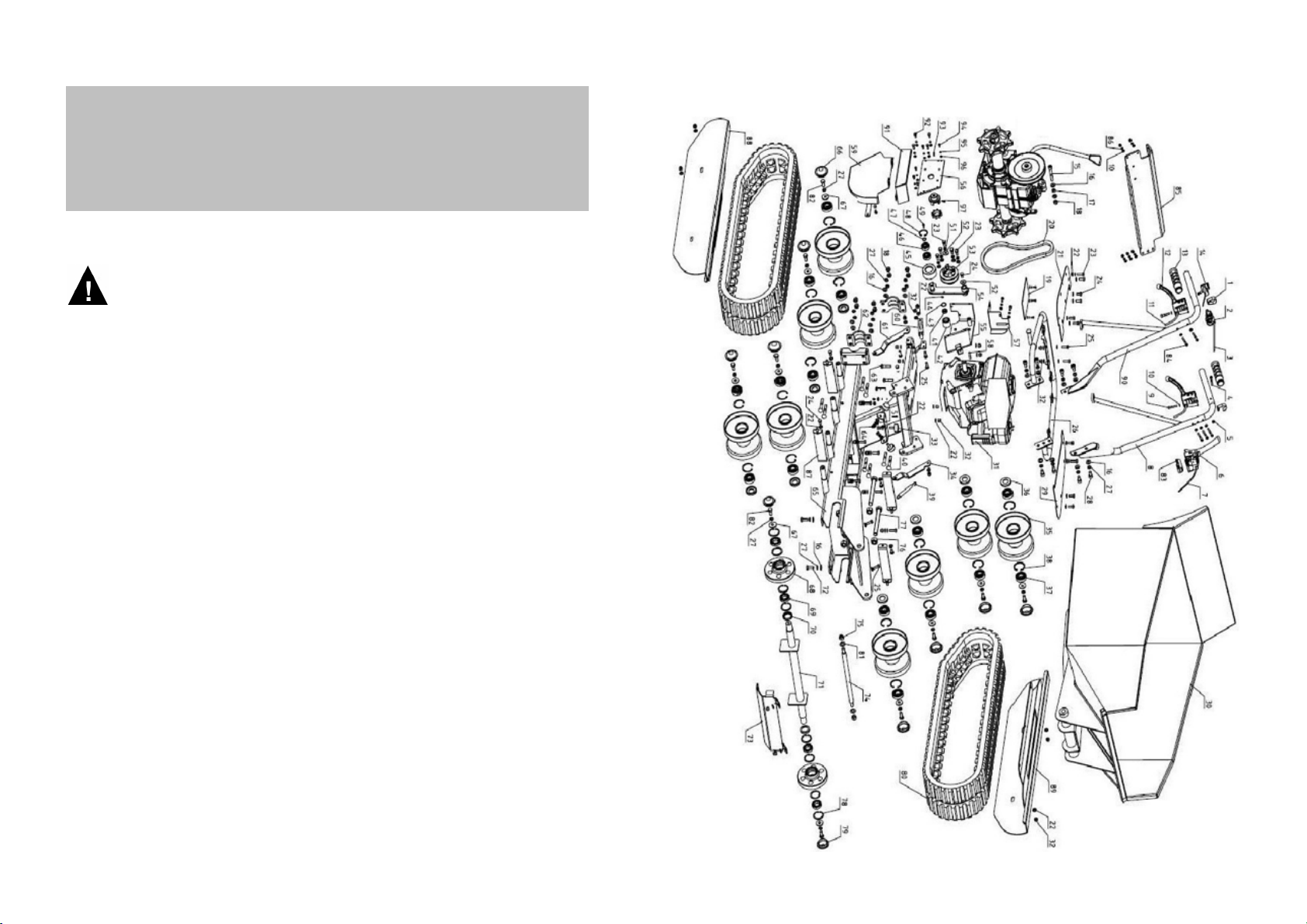
20. Exploded Diagram Track Dumper RMD650 / RMD650-B
4
21
Noise Hazard
Warning! Excessive noise can lead to temporary or permanent hearing loss. Always
wear appropriate hearing protection which has been approved to the relevant safety
regulations to limit noise pollution!
Make sure that you do not come into contact with the exhaust or other hot parts!
Touching these parts can result in serious burns.
Only allow the machine to be repaired and adjusted by trained personnel!
20
5
Fire and Explosion Hazards
Chemical Hazards
Petrol is highly flammable and explosive under certain conditions. Only store petrol
only in an appropriate container! Never refuel a petrol engine while it is operating or
before it has cooled down! Never refuel in the vicinity of sparks, open flames or
smoking persons! Avoid overflowing and spilling petrol when refuelling!
When refuelling, ensure you are in a safe position for the machine and the operator
in order to avoid petrol spills! If fuel is spilled, make sure that the area on which you
start the machine is dry, because gasoline or gasoline vapours can ignite. Make sure
that the fuel cap is securely closed after refuelling!
Do not operate or refuel any diesel or petrol engine in poorly ventilated areas, such
as deep holes or enclosed spaces! Inhalation of fuel vapours and exhaust fumes
can cause death. If you are working in trenches, ensure there is adequate
ventilation! If necessary, are set up fans.
Mineral oils and fuels are harmful to health. Therefore you should always wear
suitable protective equipment, such as Safety goggles and protective gloves, when
handling any these substances. Direct skin contact should be avoided.
In the event of skin contact: wash immediately with soap and water. If fuel or oil
comes into contact with your eye, you must seek immediate medical attention.
Petroleum and fossil fuels are harmful to the environment. Only dispose of
discharged and spilled mineral oils or fuels in accordance with the applicable local
and national environmental regulations.
Air filter dirty
Clean / replace air filter
Blocked carburettor
Clean carburettor and nozzle
Defective spark plug
Replace spark plug
Engine losing power
Belt loose
Tighten belt
Engine speed too low
Refill with new fuel
Spark plug wet
Adjust engine speed
Park brake does not release
Adjust or replace park brake cable
Belt broken or defective
Replace belt
Fuel regulation faulty
Check / adjust throttle control
Decreased traction or no
traction
Hydraulic oil level too low
Check level / top up hydraulic oil
Flow control valve fully turned
Loosen flow control valve
Hydraulic hoses / connections loose
Secure / tighten hydraulic hoses &
connections
Skip does not tip / lower (or
does not tip / lower fully)
Protective Clothing
Other Risks
Slips, trips and falls are the main causes of serious or even fatal injuries.
Avoid uneven or slippery work surfaces!
Avoid working near unprotected holes or trenches!
4. Operator Requirements
Only qualified and trained personnel over 18 years are allowed to operate the
machine. The operator must be physically and mentally healthy and productive.
The operator must have carefully read and understood the operating instructions and
be familiar with the necessary safety precautions and safety devices before using the
equipment.
5. Applications
Earthwork and bulk transport
Landscaping and paving
Roads, paths and civil engineering
Forestry
6. Conditions and Intended Operation
Requirements for the use of the Track Dumper:
•Only operate with perfect technical condition.
•Regular maintenance should be carried out according to the specifications of
this manual.
•All relevant safety conditions are met.
Intended Use of the Track Dumper:
•Transport of bulk materials
18. Tightening Torques
6
19
Always wear ear protection!
Wear goggles and dust mask in dusty environments!
Always wear safety shoes and proper protective clothing!
Wear a Helmet!
Tensile Strength
4.6
8.8
10.9
12.9
Tightening Torque (Nm)
Thread Size
M6
3.5
10
15
18
M8
8.4
25
36
43
M10
17
49
72
84
M12
29
85
125
145
M16
71
210
310
365
19. Fault Finding
Fault Cause Solution
Engine emits black smoke
Air filter dirty
Replace air filter
Air filter dirty
Replace air filter
Old fuel
Refill with new fuel
Spark plug wet
Dry spark plug
No ignition spark
Check ignition / ignition switch
Clogged carburettor
Clean carburettor and nozzle
Low engine oil level
Add oil to the correct level
Engine doesn’t start
Air filter dirty
Replace air filter
Choke closed
Check position of the choke lever
Fuel supply blocked
Check fuel supply / carburettor
Engine stalls

This Track Dumper Is Not Suitable For:
•Transport of people
•Transport of overhanging cargo
•Transport of liquids
Intended Use
The operator must be located, and must control the device carefully from, behind the
unit with hands on the controls during operation. The operator must wear proper
protective equipment such as hearing protection, safety helmet, safety goggles and
protective shoes. There should be no other people in the immediate vicinity of the
device, because of the risk of injury from moving parts and possibly from ejected
material. If the operator leaves the working position, the machine must be shut
down.
The machine may only be operated fully assembled in operation. If any parts are not
fully assembled or need replacing, e.g. Air filter, possibly battery cover, ... etc. and in
particular protective equipment such as belt guard, heat protection, exhaust or on/off
switch, the equipment must not be operated.
Operate the machine in such a way as to remove any overturning or risk of falling on
edges or embankments. The machine is to be guided such that the operator is not in
the direction of fall if an unforeseen tilting of the machine occurs.
When working on an incline, always take care not to exceed the maximum
admissible inclination stated in the technical data.
Transport
Always turn off the machine and allow the engine to cool before transporting the unit.
Prevent the unit from overturning, slipping or falling during transport with suitable
tested, lashing equipment. The lashing belts may only be fixed to the places
designated below:
17. Description - Engine
18
7
Lashing Attachment
Points (rear)
Lashing Attachment
Points (front)
1. Filler cap
2. Fuel tank
3. Throttle
4. Starter handle
5. Pull starter
6. Air filter
7. Valve cover
8. Spark Plug Cap, Spark plug
9. Exhaust and silencer
10. Choke
11. Low oil sensor
12. Oil filler and dipstick
13. Oil drain plug
14. ON / OFF switch
15. Fuel tap
Loncin G270F

Lifting
Use only suitable and approved hoists, slings and lifting accessories with sufficient
capacity. Use only permissible lifting points according to the instruction manual and
ensure that the machine is secured reliably on the hoist. There must be no persons
in the immediate vicinity of the machine when lifting.
Storage
After operation, the cooled device should be protected from the weather and stored
out of the reach of children. For storage of more than one month, the fuel must be
drained during storage. For petrol engines, the carburettor must be emptied.
16. Technical Data
For damage caused by improper use, handling, disregard of
operating instructions, impermissible overspeed, deficient or
insufficient maintenance or separate structural changes carried out
without approval of the manufacturer, machine warranty, and the
liability of the manufacturer and the dealer, will be voided. The risk in
case of these events is solely with the operator.
Be sure to read the safety instructions and commissioning
instructions before starting the machine for the first time!
7. Before Starting
1. Read the Safety section of the Operating Instructions!
2. Check the engine oil level prior to each start-up!
3. Make sure that the machine is clean, especially the cooling air inlet of the engine
and the air filter! If the air filter is dirty it must be replaced!
4. Check all nuts and bolts are tight. Normal operating vibrations can loosen
screws/nuts/bolts and this can lead to serious accidents and/or damage to the
machine.
Check the Engine Oil
1. Place the switched off machine on a flat, level surface.
2. Remove dipstick and wipe.
3. Replace the dipstick again, then remove it and read the oil level.
4. If the oil level is low, add engine oil according to the "Technical Data” section!
8
17
Model RMD650 RMD650-B
Operating weight - Unladen (kg) c. 305 c. 300
Engine Loncin G270F Briggs & Stratton 900
Single-Cylinder 4-Stroke Petrol OHV
Rated capacity (kW) 6.6 not stated by B&S
Max permitted speed (rpm) 3600 3600
Engine oil content (l) 1.0 (SAE10W-40) 0.59 (SAE10W-30)
Spark plug E7RTC QC12YC
Electrode spacing (mm) 0.7 0.76
Fuel Unleaded Petrol (RON95) or Super E10
Tank capacity (l) 5.5 2.8
Max. permitted inclination 20º 20º
Gears 3 Forward, 1 Reverse
Engine starting Recoil Recoil
Skip tipping Hydraulic Hydraulic
Max. angle of tip 110º 110º
Skip dimensions (mm) 970x710x465 970x710x465
Track width (mm) 180 180
Dimensions LxWxH (mm) 1660x720x980 1660x720x980
Lash
Intake Valve (mm) 0.15 0.15
Outlet Valve (mm) 0.20 0.28

20
19. Explosionszeichnung BAUMAX® VP16/44
9
4. Wenn der Ölstand zu niedrig ist, Motoröl entsprechend dem Kapitel „Technische
Daten“ nachfüllen!
Kraftstoffkontrolle
Benzintank öffnen und den Kraftstofffüllstand prüfen. Beim Nachtanken einen Filter
verwenden, damit kein verunreinigtes Benzin eingefüllt wird. Kein Benzin überlaufen
lassen. Wenn doch etwas daneben gelaufen ist, gründlich wegwischen, bevor der
Motor gestartet wird!
Keilriemenkontrolle
Niemals die Keilriemenspannung prüfen, während der Motor läuft! Wenn die Hände
von den Keilriemen oder der Kupplung erfasst und mitgerissen werden, können
schwere Verletzungen entstehen. Daher ist vor der Keilriemenkontrolle bei
Maschinen mit Benzinmotor der Zündkerzenstecker von der Zündkerze zu
entfernen. Bei den Arbeiten zur Keilriemenkontrolle immer Schutzhandschuhe
tragen. Um die Keilriemenspannung zu prüfen, die Schrauben der
Keilriemenabdeckung entfernen und die Abdeckung abnehmen. Die Keilriemen sind
richtig gespannt, wenn sie sich in der Mitte (zwischen beiden Riemenscheiben) ca.
10-30 mm eindrücken lassen.
8. Inbetriebnahme
Voraussetzungen für den Start
Genügend Kraftstoff befindet sich im Kraftstofftank.
Es befindet sich die richtige Menge an Motoröl im Kurbelgehäuse des Motors.
Der Luftfilter ist sauber.
Vorgehensweise beim Start
1.
Kraftstoffhahn öffnen, indem man
den schwarzen Hebel nach rechts
(in Pfeilrichtung) bis zum
Anschlag bewegt.
Ausnahme: Typ VP10/31 – kein
Kraftstoffhahn vorhanden
Tracks Tensioning Bolts
Check the Fuel Level
Open fuel tank and check the fuel level. When refuelling, always use a filter to
ensure that no contaminated fuel enters the tank. Do not allow petrol to overflow! In
the event that any fuel is spilled, thoroughly wipe off before the engine is started!
Check the Belt Tension, Drive Clutch Setting
Never check the belt tension while while the engine is running! If your hands are
caught in the belt or the clutch, serious injury can result. Therefore, before checking
the belt tension, always remove the petrol engine spark plug cap from the spark
plug. Always wear protective gloves when checking the V-belt tension.
A belt which is too loose will affect the efficiency of the machine. For details on
tightening belt tension, see Chapter 12 - Care and Maintenance.
8. Start-up
Preconditions for Starting
There is sufficient fuel in the petrol tank.
The engine crankcase has the correct oil level.
The air filter is clean.
How To Start
1.
Open the fuel tap:!
Loncin G270F engine - move black lever to the right (arrow direction) until it stops.
Briggs & Stratton 900 engine - turn red knob to the left.
16
9
12. Maintenance Intervals
All maintenance must be carried out at the listed time
or working hours interval, whichever comes first!
Before every
use
After first 5 hrs
Every 3 months
or 50 hrs
Every 6 months
or 100 hrs
Every year or
200 hrs
Engine Oil (SAE10W-70)
Check level
X
Change
X
X
Air filter
Check
X
Clean
If dirty
Replace
X (1)
Hydraulic oil
Check level
X
Transmission oil (SAE80)
Change
X
Fuel line and connections
Check
X
X
Fuel tank and filter
Clean
X
Spark plug
Check / Adjust
X
Replace
X
Idle speed
Check / Adjust
X
Full throttle speed
Check / Adjust
X
X
Engine cooling fins
Clean
If dirty
Screws and bolts
Check / re-tighten according
to torque table
X
X
Recoil start
Clean
X
Cable
Check for damage
X
Valve clearance
Check / Adjust
X
Belt tension
Check / Adjust tension
As required, if driving force of Track Dumper reduces
Steering Brakes
Check / Adjust
If Track Dumper steering is biased to left or right
Throttle
Adjust friction
As required
(1) Replace more frequently in dusty environments (at the latest, as soon as the filter material has a greyish discolouration).

2.
Turn the red On / Off switch on the right-hand guide handle to the “ON” position.
ATTENTION! For version with Briggs & Stratton 900, also move the red ignition
switch on the engine to the “I” position.
3.
Loncin G270F Engine
Move the grey Choke Lever left to the
“START” position. This causes the fuel-
air mix to be enriched and is necessary
for cold start of the engine.
Once the engine is started and running,
m o v e t h e C h o k e L e v e r t o t h e
“OPERATION” position, which provides
the correct fuel-air mix for normal work.
Briggs & Stratton
Move the black Choke Lever right to the
“START” position. This causes the fuel-
air mix to be enriched and is necessary
for cold start of the engine.
Once the engine is started and running,
move the Choke Lever to the “RUN”
position, which provides the correct fuel-
air mix for normal work.
10
15
Briggs & Stratton 900 engine both engine variants
START
OPERATION
Loncin G270-F engine
Briggs & Stratton 900 engine
START
13. Steering and Braking Adjustment
If the Track Dumper does not steer left and right correctly, readjust the steering
Bowden cables on the left and right steering levers.
1. Loosen the lock nuts of the Bowden cable adjusting screws on the steering
levers.
2. Unscrew the Bowden cable adjusting screw to loosen them further.
3. Perform a test drive and check steering characteristics by alternately pressing
the left and right steering levers.
4. The steering brakes are correctly adjusted when approximately 2/3 of lever
travel steers the Track Dumper in the desired direction.
5. If the setting is too tight it will block the steering brake.
6. When both steering brakes are evenly adjusted, tighten the lock nuts on the
Bowden cables to prevent slip.
14. Track Tensioning
The crawler tracks can stretch and/or require tightening after some time.
How to Check the Track Tension
1. Park the Track Dumper on a flat, level surface.
2. Lift the top of the track in the middle by hand.
3. If the track can lift by more than 5-6cm relative to the horizontal, the tracks
should be tightened.
Retightening the Tracks
1. Start the engine and tilt the skip far enough forward that the clamping bolts are
easily accessible.
2. Stop the engine and remove the spark plug cap to prevent accidental engine
starting.
3. Position the gear lever in the “NEUTRAL” position.
4. Chock the Track Dumper to prevent unintended rolling back or forth.
5. Secure the skip against unintentional lowering (e.g. with a prop).
6. Loosen the locknuts on the tensioning bolts and wind the tensioning bolts
clockwise to increase the track tension.
7. While tightening, check frequently the track tension by lifting the top of the track
in the middle (as described above) and check the lift.
8. Tighten both tracks equally, and then secure the locknuts.
9. The correct tension is achieved when both tracks have about 3-4 cm lift in the
middle, relative to the horizontal.

4.
Set the throttle to half throttle position.
7.
After cold start, if the engine runs smoothly, move the choke lever slowly back to
the “OPEN” position after around 5-15 seconds.
After warm start, move the choke lever to the “OPEN” position immediately.
14
11
8.
After warm-up, move the throttle lever towards full throttle position until resistance is
felt.
If making repeated attempts to start, always wait for the engine to come to a
complete stop before trying again.
5.
Pull the starter rope out slowly until a
slight resistance is felt; then pull the cord
rapidly.
PULL START
6.
Place the throttle back to the idle position and allow the engine to warm up for 1-2
minutes depending on the ambient temperature.
ATTENTION! The throttle lever must not be forced past the full
throttle position, otherwise the engine speed limit will be too high,
resulting in damage. This can lead to incorrect resonance on other
components and thus damage the entire machine. The same applies
to increasing the maximum speed setting.
ATTENTION!
DO NOT pull the starter rope all the way out to the end!
Make sure that the cable is retracted as quickly as possible without letting
go of it during retraction - so that it is drawn all the way in to the housing.
ATTENTION! Operation of the machine with too heavily soiled, defective, or
incorrectly seated air filter will cause damage to the engine. Such operation will
void the warranty and guarantee.
Belt
ATTENTION! Never try to tension the belt while the engine is running! Serious
injury can occur from moving belts! Always remove the spark plug from machines
with petrol engines before starting any maintenance to avoid accidental starting of
the engine!
Tighten the belt when transmission power feels low or disappears (e.g. if there is a
problem in overcoming gradients).
Adjusting the Belt Tension
1. Loosen the engine bolts.
2. Move the engine manually back until the right belt tension is achieved.
3. Re-tighten the engine bolts.
4. IMPORTANT! After adjusting the belt tension, check that the brakes disengage
correctly.!
Try to rotate the brake drum on the left side of the transmission with one hand,
while operating the red clutch lever with the other hand.!
While holding the red clutch lever, the brake drum must turn freely in its fixture. !
When the red clutch lever is released, the brake drum must not rotate in its
fixture.!
If necessary, the brake cable connection must be adjusted on the belt tensioner.
Transmission Oil Change
Remove the oil drain plug at the bottom of the left side of the gearbox. Using a
suitable hoist, slightly tilt the Track Dumper to the left and allow all the oil to drain
into a suitable container. Always dispose of drained oil in accordance with local and
national environmental regulations for disposal. To refill, slightly tilt the Track Dumper
to the right using a suitable hoist and fill with gear oil as specified in the technical
data. Replace the oil drain plug and tighten.
ATTENTION! When the transmission power deteriorates noticeably, the belt
tension must be checked and adjusted!
11. Shut Down
1. Set throttle to idle position.
2. Turn the engine ignition switch to the “OFF” position.
3. Always close the fuel tap after turning off.
12. Care and Maintenance
Before carrying out any maintenance work, turn off the engine and allow to cool.
For devices with petrol engines remove the spark plug and, if necessary, disconnect
the battery. If disassembly of any safety equipment is required for maintenance, it
must be assembled and checked again immediately after completion of the work.
Check for loose screws and tighten according to the specified tightening torques.
12
13
9. Driving the Track Dumper
Select the desired gear using the shift lever.
If selection is not easy/possible, press and release the clutch lever then try again.
When the desired gear has been engaged, grip and hold the red clutch lever to start
driving.
To stop the Track Dumper, slowly release the clutch lever - this disengages drive and
applies the brake!
On steep inclines always select 1st gear to avoid excessive load on the belt drive.
The Track Dumper is steered by means of the two clutch handles below the left and
right guide handles. Grip the lever on the right guide handle to cause the Track
Dumper to veer or rotate to the right. Grip the lever on the left guide handle to cause
the Track Dumper to veer or rotate to the left.
Depending on the load and the on the incline of any slope to be climbed, different
levels of force are required to actuate the levers. In extreme cases (e.g. on a slope
and with a full load) the clutch lever can no longer be operated because the force to
be transmitted is simply too large.
When driving forwards downhill (i.e. with the load at the front) take care that the
Track Dumper does not tilt because of the centre of gravity being so far forward. If in
doubt, always use reverse gear.
IMPORTANT! Gears may only be switched/selected when the red clutch lever is
NOT engaged.
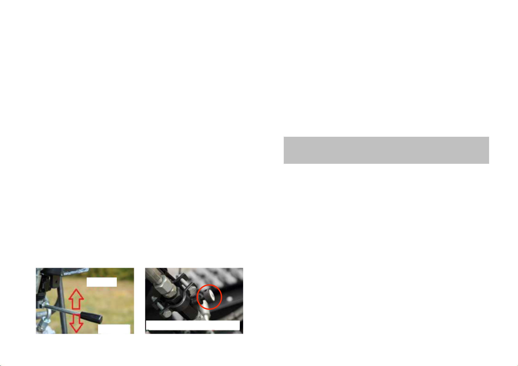
10. Tipping the Skip
Pulling upwards on the lever of the hydraulic valve under the oil tank causes the skip
to be raised.
Pushing downwards on the lever of the hydraulic valve under the oil tank causes the
skip to lower. The speed of lowering is controlled by the built-in Flow Control Valve
(see photo) - adjust as necessary. Turn the screw clockwise to reduce the lowering
speed.
ATTENTION! The valve must never be closed completely otherwise the hydraulic
pump will be overloaded!
RAISE
LOWER
FLOW CONTROL VALVE
ATTENTION! If the machine will not be used for more than 3 weeks, empty the
fuel tank and carburettor! (Drain plug: angled screw on gold float housing below
the carburettor).
Engine Oil Change
Remove the oil drain plug at the bottom of the engine (note: there are two). Using a
suitable hoist, tilt the device forward and allow all the oil to drain into a suitable
container. Always dispose of drained oil in accordance with local and national
environmental regulations for disposal. Oil changes are best carried out with a warm
engine, as warm oil flows much better and the crankcase is better drained. Then,
replace the oil drain plug(s) and tighten according to the technical data
specifications, and fill the appropriate amount of engine oil in the dipstick hole.
Alternatively, the oil can be sucked out from the dipstick hole by means of a plastic
syringe and a suction hose.
Air Filter
The air filter element should be replaced - whenever necessary - because dirty air
filters causes starting problems, reduced engine performance, and can significantly
shorten the life of the engine. To replace the air filter, undo the wing nut on the air
filter housing. After removing the cover, undo the second wing nut (not available with
VP10/31) and take out the filter element. Insert a new filter element, lock with a wing
nut and mount the cover in reverse order. When inserting and securing the filter
element ensure the correct position and cleanliness of the sealing surfaces!
This manual suits for next models
1
Table of contents


