The Handy THGT500-A User manual

226KG (500LB)
TIPPER TOWED TRAILER
Model No: THGT500-A -- Product No: 193843001
ASSEMBLY REQUIRED
SAVE THESE INSTRUCTIONS
SPARES & SUPPORT: 01793 333212
Please read & understand this manual, paying particular attention to the safety instructions,
before use.
The manufacturer reserves the right to change the product specification and livery
according to continued product improvements.
Images used are for illustration purposes only
INSTRUCTION MANUAL


CONTENTS
SAFETY INSTRUCTIONS
SPECIFICATIONS
CONTROLS & FEATURES
OPERATING INSTRUCTIONS
MAINTENANCE & STORAGE
COMPONENTS
ASSEMBLY
PARTS DIAGRAM & LIST
WARRANTY
ASSEMBLY IS REQUIRED
This product requires assembly before use. See the “Assembly” section for instructions.
Please check that all parts required for the assembly of this spreader are included. If for any reason
you believe a part for the assembly is missing or damaged, please contact us.
If you require any assistance with regards to the contents or operation of
your machine, please contact us:
TEL: 01793 333212
(MON –FRI 8.00AM TO 5.30PM EXCL. BANK HOLIDAYS)

SPECIFICATION
The manufacturer reserves the right to change the product specification and livery according to
continued product improvements.
Model
THGT500-A
Product Number
193843001
Weight
38.7kg
Working Width
81cm
Internal Dimensions
97cm x 71.5cm x 30.5cm
Maximum Capacity
500LB (226kg)
Wheel & Tyre
16”Pneumatic
Tyre PSI (Recommended)
25 PSI (Do not exceed)
IMPORTANT INFORMATION
INTENDED USE
The product is intended for domestic gardens. This product is not intended for commercial use.
Generally acknowledged accident prevention regulations and enclosed safety instructions must be
observed. Only perform work described in these instructions for use, any other use is incorrect. The
manufacturer will not assume responsibility for damage resulting from such use.
GENERAL SAFETY INSTRUCTIONS
Read and understand the owner’s manual
and labels affixed to the product. Learn its
application and limitations as well as the
specific potential hazards. Retain these
instructions for future reference. The
operator is responsible for following the
warnings & instructions in this manual and
on the product.
READ THE MACHINE MANUAL
Read the vehicle owner’s manual and vehicle
safety rules, and know how to operate the
vehicle before using this equipment.
STAY ALERT
Do not operate the machine while under the
influence of drugs, alcohol, or any medication
that could affect your ability to use it properly.
Do not use this machine when you are tired or
distracted from the job at hand. Be aware of
what you are doing at all times. Use common
sense.
USERS
Never allow children to operate the towing
vehicle or de-thatcher. Do not allow adults to
operate without having read these instructions.
TYRE INFLATION
Only use HAND or FOOT operated tyre inflation
machines, not mechanical and do not exceed
recommended PSI.
PASSENGERS
Do not allow anyone to ride or sit on the de-
thatcher frame or on the towing vehicle.
BEWARE BYSTANDERS/PETS
Keep the area of operation clear of all persons,
particularly children and also pets.
HANDLE WITH CARE
Always handle with care and wear sturdy
footwear when operating this attachment.
AVOID DANGEROUS CONDITIONS
Make sure there is adequate surrounding
workspace. Cluttered areas invite injuries.
Keep your work area clean with sufficient light.
Keep the area around the machine clear of
obstructions, grease, oil, rubbish & other debris
which could cause persons to fall onto moving
parts.
DO NOT FORCE TOOL
Always work within the rated capacity. Do not
operate for a purpose for which it was not
intended.
INSPECT YOUR MACHINE
Check all bolts, nuts & screws for tightness
before each use, especially those securing
guards & drive mechanisms. Vibration during
use, may cause these to loosen. Replace
damaged, missing or failed parts before using.

CRUSH AND CUT HAZARDS
Always keep your hands and feet clear from
moving parts while operating. Always keep the
work area clean and clear when operating.
CONDITIONS
Always operate up and down a slope, never
across the face of a slope. This equipment
should be operated at reduced speed on rough
terrain, along creeks and ditches and on
hillsides, to prevent tipping and loss of control.
Do not drive too close to a creek or a ditch. Do
not tow this equipment on a highway or any
other public thoroughfare.
Always begin with the transmission in first (low)
gear & the engine at low speed. Gradually
increase the speed as conditions permit. The
vehicle braking and stability may be affected
with the sweeper attached. Be aware of
changing conditions on slopes.
Refer to safety rules in the vehicle owner's
manual, concerning safe operation on slopes.
DRESS PROPERLY
Do not wear loose clothing, gloves, scarfs,
neckties or jewelry (rings, wrist watches), which
can be caught in moving parts.
DO NOT OVERREACH
Never stand on the machine. Serious injury
could occur if tipped or moving parts are
unintentionally contacted. Do not store anything
above or near the machine, where anyone might
stand on the machine to reach them.
AVOID INJURY FROM UNEXPECTED ACCIDENT
Keep hands & feet out of the way of all moving
parts. Do not place any part of your body or
any tool e.g. in moving parts of the machine
during operation.
MAINTAIN YOUR MACHINE WITH CARE
Clean the machine immediately after use. Keep
the machine clean to ensure it operates to its
full & safest performance. When maintaining
this machine, only the manufacturer’s original
replacement parts should be used. The use of
non-original manufacturer parts may invalidate
your warranty.
PROTECT THE ENVIRONMENT
Take left over materials to an authorised
collection point or follow the stipulations in the
country where the machine is used. Do not
discharge into drains, soil or water.
STORE IDLE EQUIPMENT
When not in use, the machine should be stored
in a dry location. Keep the machine away from
children & others not qualified.
OPERATION SPEED
Do not exceed 10mph, to avoid personal injury
and/or equipment damage.
SAFETY SYMBOLS
Safety alert symbol. Used to alert you to
potential personal injury hazards. Obey all
safety messages that follow this symbol to avoid
possible injury.
DANGER
Indicates an imminently hazardous situation
which, if not avoided, will result in serious
injury.
WARNING
Indicates a potentially hazardous situation
which, if not avoided, could result in serious
injury
CAUTION
Indicates a potentially hazardous situation
which, if not avoided, may result in minor or
moderate injury.
CAUTION
Used without the safety alert symbol indicates a
potentially hazardous situation which, if not
avoided, may result in property damage.
Read & understand
operator’s manual before
using the machine. Failure
to follow instructions could
result in death or serious
injury.
Risk of Slicing.
Keep hands out of the way
of all moving parts.
Wear gloves to protect your
hands
Wear foot protection

COMPONENTS
Please check the contents of the carton are correct BEFORE assembling your new product.
If any parts are missing, contact our Customer Service Team
•Telephone: 01793 333212
•Email: customerservice@handydistribution.co.uk
TOOLS REQUIRED
•Pliers
•Screw Driver –Phillips Head
•10mm & 14mm Wrench
Left Bottom Panel x1
Right Bottom Panel x1
Right Side Panel x1
Left Side Panel x1
Front Panel x1
Rear Panel x1
Wheel Axle Support x2
Tow Bar & Hitch x1
Wheel x2
Draw Bar Support x1
Wheel Axle x1
Support Tube x2
Rear Panel Slot x2
Release Pedal x1
Latch Spring x1
Hinge Pin x6
Hex Bolt M6x90 x1
R-Pin Ø3 x2
Flat Washer Ø16 x4
Spacer x2
Screw M6x16 x4
Screw M8x16 x8
Screw M8x20 x2
Screw M8x35 x4
Lock Nut M8 x14
Lock Nut M6 x5

ASSEMBLY
Remove the hardware pack and all loose parts from the carton and verify that all the components
are included. If you are missing any parts, please contact us on 01793 333212 for assistance.
STEP 1 - Attach the Bottom Panels and Support Tubes
•Lay the left and right bottom panels, face down
•Attach the baseboard support tubes to the panels using four sets of M8x35 screws & M8 nylon
lock nut.
•Hand tighten the nuts.
STEP 2 - Attach the Draw Bar Support
•Attach the V-Shaped draw bar support to the bottom panels using two M8x20 screws & M8 lock
nuts
•Hand tighten the nuts

STEP 3 - Attach the Wheel Axle Support
•Connect the two-wheel axle supports and attach them to the bottom panels using eight M8 lock
nut & screw M8x16.
•Hand tighten the nuts.
STEP 4 - Attach the Release Pedal
•Insert the release pedal into the tow bar and secure using the two spacers either side of the
release pedal & the M6x90 hex bolt and M6 lock nut.
•Attach the latch spring hook onto the bottom hole of the release pedal and tow bar.
•Hand tighten the nuts.

STEP 5 - Attach the Wheel Axle
•
Insert the tow bar assembly into the central slot in the wheel axle support.
•
Insert the axle through the hole and slide it through both the axle support and the Tow Bar
assembly.
•
Now tighten all nuts & bolts in steps 1 through to 4.
STEP 6 - Attach the Wheels
•
Put a Ø16 Flat Washer on the axle; slide the wheel over the end, followed by a second Ø16 flat
washers and secure with a Ø3 R-pin through hole within the wheel & axle.
•
Repeat the process for the other side of the axle.
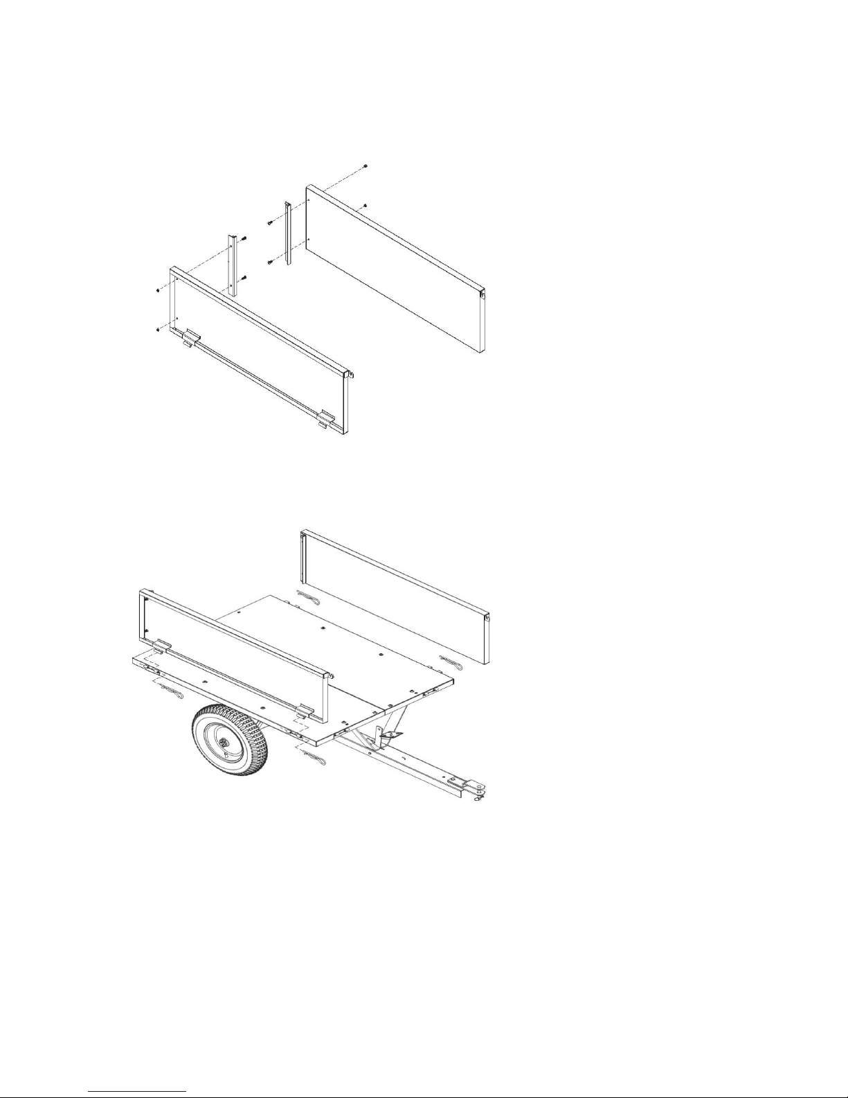
STEP 7 - Attach the Rear Panel Slots and Lock Support Tube
1. Attach the left and right rear panel slots on the left and right panel using four sets of the
M6x16 screws and M6 lock nuts.
STEP 8 - Attach the Side Panel
•Attach the left and right side panel to the bottom panel using the four hinge pins.

STEP 9 - Attach the Front Panel
•
Attach the front panel to the bottom panel and secure using two hinge pins.
•
Lock the left and right side panel assemblies in place using the top handles.
STEP 10 - Attach the Rear Panel
•Slide the rear panel through the slots on the back side panels.
NOTE: The rear panel pins must go through the holes on the side panels to lock the panel in place.
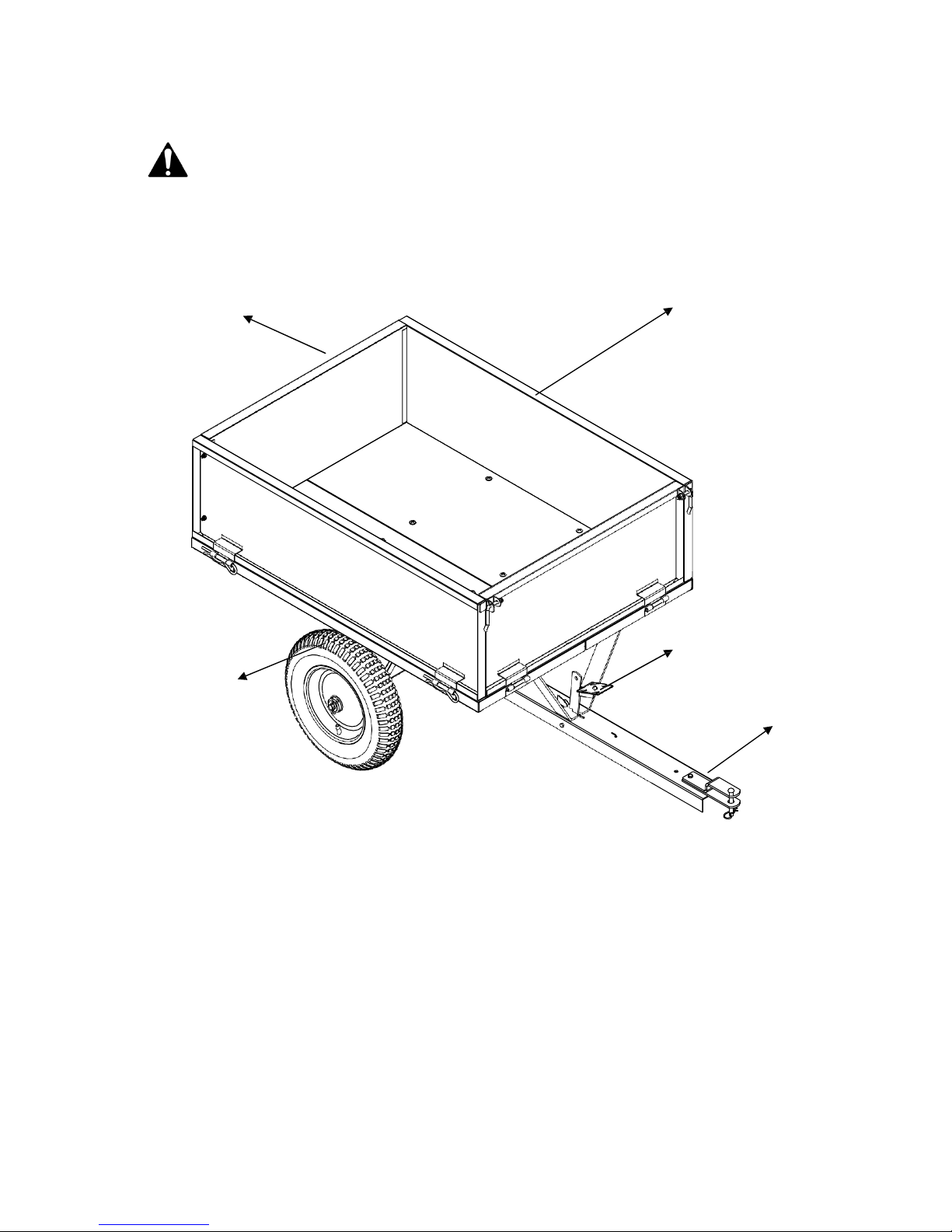
CONTROLS & FEATURES
CAUTION
Read & follow all instructions for assembly & operation. Failure to properly assemble this equipment
could result in serious injury to the user of bystanders, or cause equipment damage.
Familiarise yourself with the location& function of the controls and features.
Keep the manual in a safe place for future reference.
3
1.
Removable Tailgate –Push up to remove for loading and unloading.
2.
Trailer Box –Do not exceed rated load capacity 500lb (226.8kg).
3.
Tyres / Wheel –Check and inflate the tyres. We recommend the use of FOOT or HAND
inflation devices only. Do not inflate above the recommended 25psi.
4.
Hitch –Pin-type design, use only with approved vehicles.
5.
Release Pedal –Releases the Trailer bed for tipping.
1
2
4
5

OPERATION / ADJUSTMENT
DANGER
The product must only be put into operation if no defects are found. It is crucial that defective
parts are replaced before the product is used again. Check the safety equipment and the safe
condition of the product: Check all parts to make sure that they fit tightly. Check whether there
are any visible defects: broken parts, cracks, etc.
•THIS TRAILER CANNOT BE ATTACHED BY TOW BALL OR BEHIND A ROAD GOING VEHICLE.
•Never allow children to handle the trailer.
•Never allow anyone to ride on the trailer.
•Always wear footwear when working with the trailer.
•Never operate if the trailer is damaged, repair before continuing to operate.
•DO NOT exceed the rated capacity of 226kg (500lb).
•ALWAYS secure and lock the Trailer to the vehicle hitch before operating.
•ONLY use approved vehicles when towing the Trailer (Lawn/Garden Tractors & ATVs)
•NEVER tow the Trailer with the box raised.
•DO NOT over fill the Trailer. This could cause the Trailer and towing vehicle to lose traction
and skid out of control.
•ONLY fill the Trailer to a manageable dumping load. Extremely heavy loads will be difficult to
operate the tipping mechanism.
•ONLY use the Trailer for its intended purpose.
•ALWAYS make sure that the combined weight of the tow vehicle and the operator is greater
than the load of the Trailer. If the Trailer is heavier it may be difficult to control.
•DO NOT use the Trailer on public roads.
•NEVER exceed 10mph when towing the Trailer.
•DO NOT make sharp turns as this may cause the Lawn/Garden Tractor or ATV tyres to rub against
the Towed Trailer.
•ALWAYS slow down before turning.
•ALWAYS use caution when reversing the Trailer. To avoid the Trailer “jack-knifing” always
reverse in a straight line.
ATTACHING THE TRAILER TO THE TOW VEHICLE
•Park the tow vehicle and trailer on level ground.
•Set the height adjustment handle to middle of its adjustment.
•Insert the hitch pin through the sweeper hitch brackets and towing eye of the tow vehicle and
secure with the cotter pin.
EMPTYING THE TRAILER
•Stop the tow vehicle and turn off the engine.
•Stand to the side of the trailer.
•Ensure your footing is secure and use your foot to apply pressure to the release pedal. Ensuring
the tipping trailer does not come into contact with you.
•Release carefully to rehouse trailer to frame. Ensure it is correctly housed before starting the
engine of the towing vehicle.

MAINTENANCE
WARNING
Improper maintenance & storage of the trailer may void your warranty.
MAINTENANCE
•After each use clean any material out of the Trailer.
•Rinse/dry inside and outside of the Trailer after each use.
•Before operating make sure the tyres have the recommended tyre pressure of 25 PSI (Do not
exceed). We recommend the use of FOOT or HAND inflation devices only.
•Grease the axle and the wheel bearing area regularly with Multi-purpose grease.
•Periodically check all nuts & bolts for tightness.
•Annually clean and lightly lubricate parts with Maintenance spray.
•Use a glossy enamel spray paint to touch up scratched or worn painted metal surfaces.
•Never exceed the load capacity rating of 500lb (226.8kg) this will damage the Trailer.
IMPORTANT:
Only use the manufacturer’s original replacement parts. Non-original replacement parts will
invalidate your warranty and may result in a safety hazard or poor operation.
Parts are available by calling 01793 333212.
STORAGE
•Never allow material to remain in the Trailer for extended periods of time.
•For years of trouble free service, make sure the Trailer is clean and dry before storing.
•Store indoors or in a protected area during severe weather and winter months.
•When storing outside always keep the draw bar a little higher than the back of the Trailer to
allow any moisture to run out of the back and not to accumulate in the carry area.

PARTS DIAGRAM & LIST

PARTS LIST
Ref
Part No.
Description
Qty
Ref
Part No.
Description
Qty
1
TH177-1
Left Bottom Panel
1
20
TH177-22
Draw Bar Support
1
2
TH177-2
Right Bottom Panel
1
21
TH177-23
Pin
2
3
TH177-3
Wheel
2
22
TH177-24
Handle A
1
4
TH177-4
Wheel Axle Support
2
23
TH177-25
Handle B
1
5
TH177-5
Left Side Panel
1
24
TH177-26
Handle Sleeve
2
6
TH177-6
Right Side Panel
1
25
TH177-27
R Pin Ø4
3
7
TH177-12
Rear Panel
1
26
TH177-28
Screw M8x35
4
8
TH177-13
Release Pedal
1
27
TH177-29
Screw M8x20
2
9
TH177-9
Front Panel
1
28
TH177-33
Hex Bolt M8x16
8
10
TH177-10
Left Rear Panel Slot
1
29
TH177-31
Screw M6x16
4
11
TH177-11
Right Rear Panel Slot
1
30
TH177-30
Screw M6x35
4
12
TH177-14
Wheel Axle
1
31
TH177-34
Hex Bolt M6x90
1
13
TH177-15
Hinge Pin
6
32
TH177-35
Flat Washer Ø6
2
14
TH177-16
Support Tube
2
33
TH177-36
Flat Washer Ø8
2
15
TH177-17
Hitch Pin
1
34
TH177-37
Flat Washer Ø16
4
16
TH177-18
Hitch Bracket 1
1
35
TH177-38
Nylon Lock Nut M6
5
17
TH177-19
Latch Spring
1
36
TH177-39
Nylon Lock Nut M8
18
18
TH177-20
Spacer
2
37
TH177-40
Hex Nut M6
2
19
TH177-21
Draw Bar
1
38
TH177-41
Hitch Bracket 2
1
39
TH177-42
Large Washer Ø8
2
NOTE: Parts Lists are supplied for information purposes only, not all parts are stocked individually & we recommend
you contact our Spares Team on 01793 333212 for expert advice.

GJ HANDY & CO LTD USER WARRANTY POLICY
Users Statement of Warranty
Each new machine is warranted against defective material or assembly of material under normal
usage. The warranty applies to the original purchaser and covers faulty parts and the labour involved
in replacing and repairing those parts, which are of original manufacture.
Period of Warranty
All Webb, Handy Pro (Brushcutter & Long Handle Hedgecutter only) and Sanli domestic products.
2 years from the original date of sale to the first domestic user.
90 days from the original date of sale to the professional/commercial user.
90 days from the original date of sale when used for hire.
A reduced warranty period of 90 days applies to those items which are subject to normal wear and
tear (e.g. wheels, tyres, cutter bars, cylinders, bottom blades, belts, cables, grass bags, spark plugs).
Engines as per the manufacturer’s warranty statement which will be supplied with the machine.
90 days from the original date of purchase for Replacement Spare Parts (unless normal wear & tear
component, which are covered for 30 days).
All machines’ must be serviced within the first 12 months from the original date of purchase to
comply with the warranty, failure to do so will invalidate the 2nd year of the warranty.
All Handy, Handy Pro (All others), Mowerland and Q-Garden domestic products.
1 year from the original date of sale to the first domestic user.
90 days from the original date of sale to the professional/commercial user.
90 days from the original date of sale when used for hire.
A reduced warranty period of 90 days applies to those items which are subject to normal wear and
tear (e.g. wheels, tyres, cutter bars, cylinders, bottom blades, belts, cables, collection bags, spark
plugs).
Engines as per the manufacturer’s warranty statement which will be supplied with the machine.
90 days from the original date of purchase for Replacement Spare Parts (unless normal wear & tear
component, which are covered for 30 days).
All warranty repairs must be undertaken by an authorised service dealer. These dealers have been
accredited by GJ Handy & Co Ltd and agree to only use genuine parts and follow our repair
procedures.
Version 3 05-16

GJ HANDY & CO LTD USER WARRANTY POLICY
Not covered by this warranty
a) The warranty policy does not cover any depreciation or damages caused by ordinary wear,
rusting or corrosion, lack of correct maintenance or operation, misuse, abuse, lack of
transportation or accident.
b) The warranty policy does not cover any costs necessary for the standard periodic maintenance
services instructed by the operator’s manual, or service parts replacement which would include
oil, filters, tyres, belts, brake linings, fuses, blades, seals and other service parts unless it can be
proven that the item has evidence of faulty manufacture.
c) The warranty policy will not cover failure or damage caused as a result of parts or accessories
being modified without the written approval of GJ Handy & Co Ltd.
d) The warranty policy will not cover the unit if non-genuine parts have been fitted and as a result
damage has occurred to the unit.
e) The warranty policy is non-transferable and is only applicable to the original purchaser.
Disclaimer
a) This warranty is only a remedy for defect of products. GJ Handy & Co Ltd will never warranty in
terms of the merchantability or the fitness for a particular purpose.
b) No person is authorised to make any warranties, representations or promises, expressed or
implied, on behalf of GJ Handy & Co Ltd, or to modify the terms conditions or limitation of this
warranty policy in any way.
c) Neither GJ Handy & Co Ltd nor any company affiliated with GJ Handy & Co Ltd shall be liable in
any event or manner whatsoever for incidental or consequential damages or injuries, including,
but not limited to, loss of crops, loss of profit, out of pocket expenses or profits, rental of
substitute equipment or other commercial losses.
General
a) Most warrantable failures show up within the first few weeks of use. These failures are usually
straightforward and warranty assessment is relatively easy.
b) Failures relating to cutter decks and belts need careful investigation, as the cause may not
always be straightforward. Look for damage to blades and pulleys especially when the cutter
belt or blade boss have snapped or cracked as this could be due to impact damage.
c) Customers should always refer to the operator/instruction manual when any disputed problem
arises, you will find most areas covered within the manual.


For spares or support of your handy product,
please contact us:
Tel: 01793 333212
(Mon –Fri 8.00am to 5.30pm excl. Bank Holidays)
Email: customerservice@handydistribution.co.uk
To see our range of garden machinery & equipment visit:
www.thehandy.co.uk
Making gardening easier & affordable since 1938
Distributed by Handy Distribution, Murdock Road, Dorcan, Swindon, SN3 5HY
Other manuals for THGT500-A
1
This manual suits for next models
1
Table of contents
Other The Handy Utility Vehicle manuals


Popular Utility Vehicle manuals by other brands


Demountable Concepts
Demountable Concepts Warehouse On Wheels Quick reference guide

Madill
Madill 3000 Operation & maintenance manual

Global
Global ANV-400 Instructions for use

Polaris
Polaris RANGER RZR XP 4 900 2013 Owner's manual for maintenance and safety

DR
DR VERSA TRAILER PRO XL2000 Safety & Operating Instructions

Chapman
Chapman TF350 Original instructions