manuals.online logo
Brands
  1. Home
  2. •
  3. Brands
  4. •
  5. Baumer
  6. •
  7. Accessories
  8. •
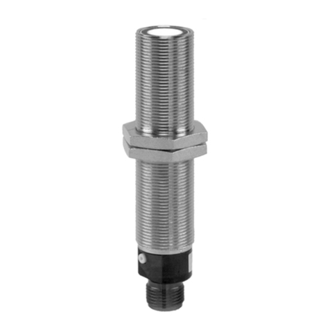
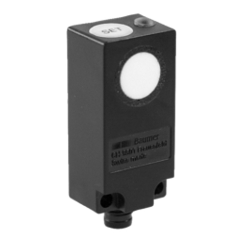
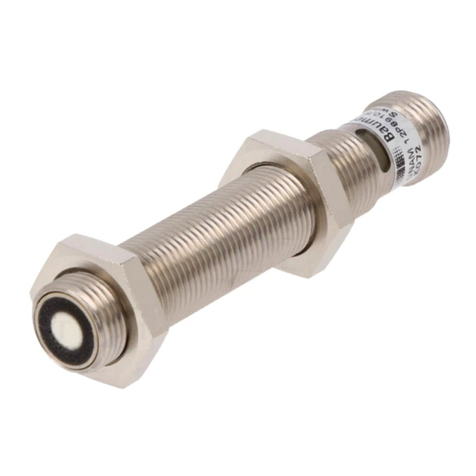
  9. Baumer UNAM 12N3912/S14 User manual

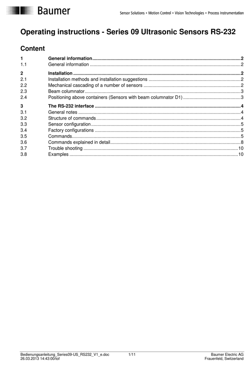
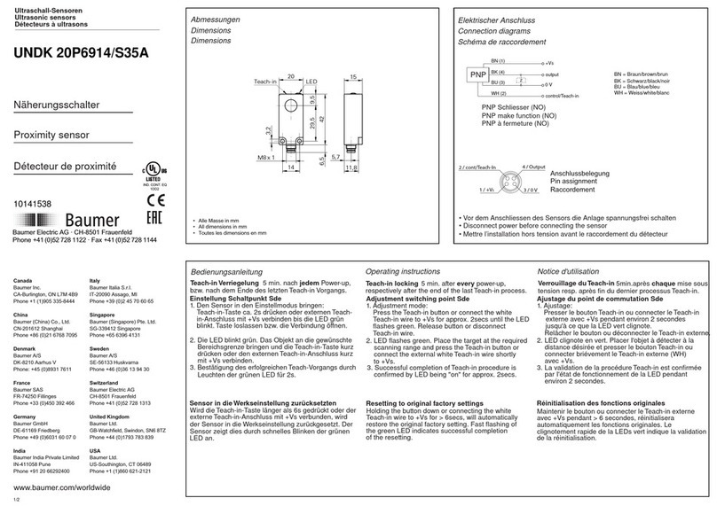
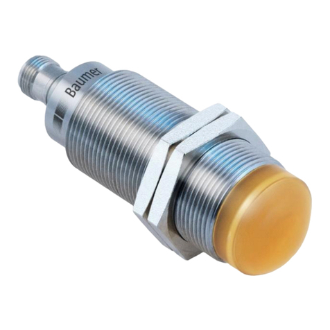
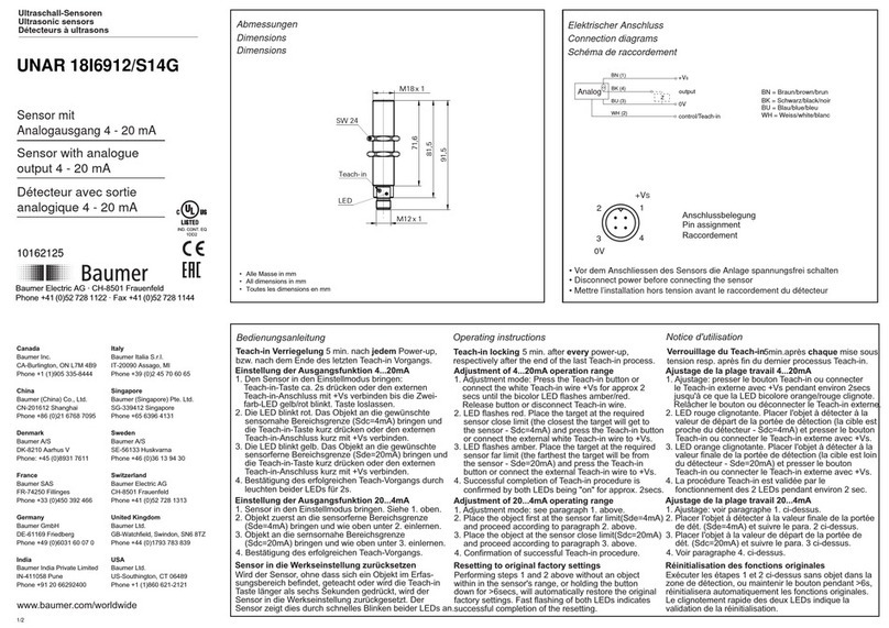
Baumer UNAM 12N3912/S14 User manual

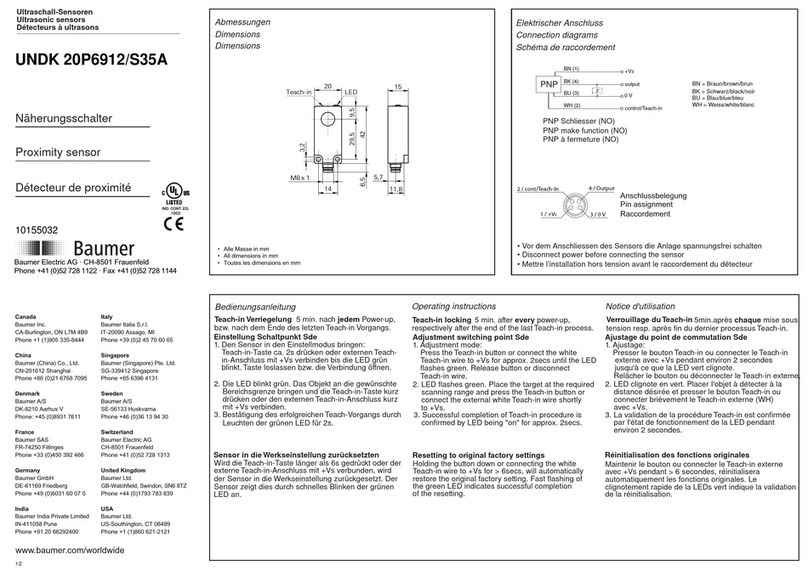
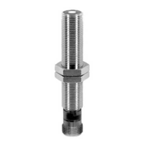
UNAM 12N3912/S14
10158528
1/2
IND. CONT. EQ.
1DD2
Ultraschall-Sensoren
Ultrasonic sensors
Détecteurs à ultrasons
Näherungsschalter
Proximity sensor
Détecteur de proximité
Canada
Baumer Inc.
CA-Burlington, ON L7M 4B9
Phone +1 (1)905 335-8444
China
Baumer (China) Co., Ltd.
CN-201612 Shanghai
Phone +86 (0)21 6768 7095
Denmark
Baumer A/S
DK-8210 Aarhus V
Phone: +45 (0)8931 7611
France
Baumer SAS
FR-74250 Fillinges
Phone +33 (0)450 392 466
Germany
Baumer GmbH
DE-61169 Friedberg
Phone +49 (0)6031 60 07 0
India
Baumer India Private Limited
IN-411038 Pune
Phone +91 20 2528 6833/34
Italy
Baumer Italia S.r.l.
IT-20090 Assago, MI
Phone +39 (0)2 45 70 60 65
Singapore
Baumer (Singapore) Pte. Ltd.
SG-339412 Singapore
Phone +65 6396 4131
Sweden
Baumer A/S
SE-56133 Huskvarna
Phone +46 (0)36 13 94 30
Switzerland
Baumer Electric AG
CH-8501 Frauenfeld
Phone +41 (0)52 728 1313
United Kingdom
Baumer Ltd.
GB-Watchfield, Swindon, SN6 8TZ
Phone +44 (0)1793 783 839
USA
Baumer Ltd.
US-Southington, CT 06489
Phone +1 (1)860 621-2121
www.baumer.com/worldwide
Baumer Electric AG · CH-8501 Frauenfeld
Phone +41 (0)52 728 1122 · Fax +41 (0)52 728 1144
Abmessungen
Dimensions
Dimensions
70
55
M12 x 1
M12 x 1
LED
SW 17
• Alle Masse in mm
• All dimensions in mm
• Toutes les dimensions en mm
Elektrischer Anschluss
Connection diagrams
Schéma de raccordement
NPN Öffner (NC)
NPN break function (NC)
NPN à ouverture (NC)
0 V
WH (2)
BU (3)
BN (1)
BK (4)
+VS
output
control/Teach-in
NPN ZBN = Braun/brown/brun
BK = Schwarz/black/noir
BU = Blau/blue/bleu
WH = Weiss/white/blanc
• Vor dem Anschliessen des Sensors die Anlage spannungsfrei schalten
• Disconnect power before connecting the sensor
• Mettre l’installation hors tension avant le raccordement du détecteur
Anschlussbelegung
Pin assignment
Raccordement
1
4
2
3
+VS
0V
Bedienungsanleitung Operating instructions Notice d'utilisation
Einstellung Schaltpunkt Sde
Teach-in Verriegelung Teach-in locking Verrouillage du Teach-in
respectively after the end of the last Teach-in process.
5 min. nach jedem Power-up, 5 min. after every power-up, 5min.après chaque mise sous
bzw. nach dem Ende des letzten Teach-in Vorgangs. tension resp. après fin du dernier processus Teach-in.
Sensor in die Werkseinstellung zurücksetzten
Externer Teach-in-Anschluss ca. 2s mit +Vs ver-
binden bis die LED grün blinkt. Die Verbindung
1. Den Sensor in den Einstellmodus bringen:
öffnen.
2. Die LED blinkt grün. Das Objekt an die gewünschte
Bereichsgrenze bringen und den externen Teach-in-
Anschluss kurz mit +Vs verbinden.
Wird der externe Teach-in-Anschluss länger als 6s mit
+Vs verbunden, wird der Sensor in die Werksein-
stellung zurückgesetzt. Der Sensor zeigt dies durch
schnelles Blinken der grünen LED an.
3. Bestätigung des erfolgreichen Teach-Vorgangs durch
Leuchten der grünen LED für 2s.
Adjustment switching point Sde
Resetting to original factory settings
Connect the white Teach-in wire to +Vs for approx.
2secs until the LED flashes green. Disconnect
1. Adjustment mode:
Teach-in wire.
2. LED flashes green. Place the target at the required
scanning range and connect the external white
Teach-in wire shortly to +Vs.
3. Successful completion of Teach-in procedure is
confirmed by LED being "on" for approx. 2secs.
Connecting the white Teach-in wire to +Vs for > 6secs,
will automatically restore the original factory settings.
Fast flashing of the green LED indicates successful
completion of the resetting.
Ajustage du point de commutation Sde
Réinitialisation des fonctions originales
environ 2 secondes jusqu'à ce que la LED clignote.
Déconnecter le Teach-in externe.
1. Ajustage:
2. LED clignote en vert. Placer I'objet à détecter a la
distance desirée et connecter briévement le
Teach-in externe (WH) avec +Vs.
3. La validation de la procédure Teach-in est confirmée
par I'état de fonctionnement de la LED pendant
environ 2 secondes.
Connecter le Teach-in externe avec +Vs pendant
> 6 secs, réinitialisera automatiquement les fonctions
originales. Le clignotement rapide de la LED vert
indique la validation de la réinitalisation.
Connecter le Teach-in externe avec +Vs pendant
UNAM 12N3912/S14
2/2
Technische Daten
Technical data
Données techniques
Betriebsspannungsbereich Vs Plage de tension Vs
Stromverbrauch Supply current Consommation
Max. Laststrom Max. load current Courant de charge max.
Kurzschlussfest Short circuit protection Protégé contre courts circuits
Ausgangsanzeige Output state indication Indication de l’état de sortie
Schutzklasse Protection class Classe de protection
Verpolungsfest
Temperaturbereich
Voltage supply range Vs
Reverse polarity protection
Temperature range
Protégé contre inversion de polarité
Température de fonctionnement
IP67
-10...60°C
LED grün/green/vert
ja/yes/oui
ja/yes/oui
200mA
<35mA
12-30VDC (UL-Class 2)
<= 0,18% Sde/K
4% Sde
(siehe Dok./see doc./consultez doc.)
60...400mm
40mm...Sde
Dérive en température
Hystérésis typ.
Faisceau sonore
Valeur final de portée de dét. Sde (pot)
Portée de détection Sd
Temperature drift
Hysteresis typ.
Sonic cone profile
Scanning range far limit Sde (pot)
Scanning range Sd
Temperaturdrift
Hysterese typ.
Schallkeule
Erfassungsbereich-Endwert Sde (pot)
Erfassungsbereich Sd
General information
Informations supplémentaires
Weitere Erläuterungen
output
VOUT
Sde
SO
scanningrange
adjusting range
ofswitchingpoints
switchingpoint output
Funktionsdiagramm
Diagramme de fonctionnement
Functional diagramm
Hinweise
Notes
Notes
Externen Teach-In nicht verwendet
Wird der externe Teach-In Eingang nicht
verwendet, muss er auf GND gelegt
werden.
External Teach-In not used,
If external Teach-In option is not used, the
Teach-In wire must be attached to GND.
Teach-in externe non utilisé
Dans le cas ou le Teach-in externe n’est
pas utilisé, il faut le raccorder avec GND.
Technische Änderungen vorbehalten Technical specifications subject to change Sous réserve de modifications techniques

Other Baumer Accessories manuals

Baumer GIM500R User manual

Baumer

Baumer GIM500R User manual

Baumer 10141538 User manual

Baumer

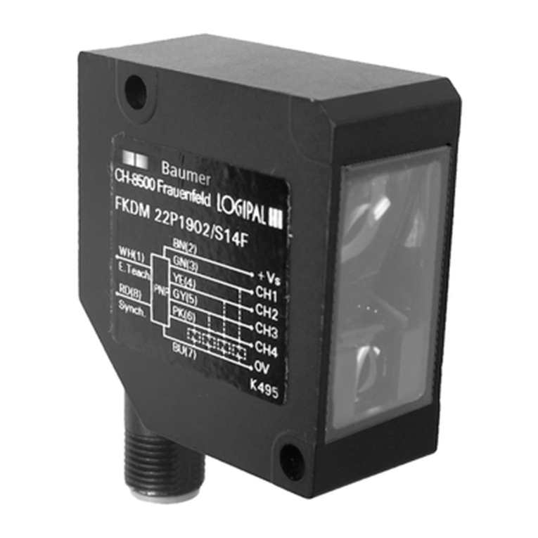
Baumer 10141538 User manual

Baumer URDK 10N8914 User manual

Baumer

Baumer URDK 10N8914 User manual

Baumer 18N6903/S14 User manual

Baumer

Baumer 18N6903/S14 User manual

Baumer OADM 12I6430/S35A User manual

Baumer

Baumer OADM 12I6430/S35A User manual

Baumer UNDK 10N8914/KS35A User manual

Baumer

Baumer UNDK 10N8914/KS35A User manual

Baumer OADM 20I6560/S14F User manual

Baumer

Baumer OADM 20I6560/S14F User manual

Baumer UNCK 09U6914/D1 User manual

Baumer

Baumer UNCK 09U6914/D1 User manual

Baumer UNAM 18P6903/S14 User manual

Baumer

Baumer UNAM 18P6903/S14 User manual

Baumer UNDK 20P7914/S35A User manual

Baumer

Baumer UNDK 20P7914/S35A User manual

Baumer UNAR 18N6903/S14G User manual

Baumer

Baumer UNAR 18N6903/S14G User manual

Baumer OM70 User manual

Baumer

Baumer OM70 User manual

Baumer OADM 20I6580/S14F User manual

Baumer

Baumer OADM 20I6580/S14F User manual

Baumer URAR 12P8914/S14H User manual

Baumer

Baumer URAR 12P8914/S14H User manual

Baumer FVDK 10P65Y0/KS35A User manual

Baumer

Baumer FVDK 10P65Y0/KS35A User manual

Baumer FVDK 10N66YS User manual

Baumer

Baumer FVDK 10N66YS User manual

Baumer UNDK 10N8914/KS35A User manual

Baumer

Baumer UNDK 10N8914/KS35A User manual

Baumer UNAM 12N1912/S14 User manual

Baumer

Baumer UNAM 12N1912/S14 User manual

Baumer R600V.DAE0-11209335 User manual

Baumer

Baumer R600V.DAE0-11209335 User manual

Baumer UNCK 09G8914/KS35A User manual

Baumer

Baumer UNCK 09G8914/KS35A User manual

Baumer UNDK 10N8914/KS35A User manual

Baumer

Baumer UNDK 10N8914/KS35A User manual

Baumer OM70-11199109 User manual

Baumer

Baumer OM70-11199109 User manual

Baumer GNAMG. 213P Series User manual

Baumer

Baumer GNAMG. 213P Series User manual

Baumer UNDK 20P7912/S35A User manual

Baumer

Baumer UNDK 20P7912/S35A User manual

Popular Accessories manuals by other brands

LEGRAND WS-250 installation instructions

LEGRAND

LEGRAND WS-250 installation instructions

procontrol IP STECKER User and installation manual

procontrol

procontrol IP STECKER User and installation manual

Datexx SUPERBattery LED-99 user manual

Datexx

Datexx SUPERBattery LED-99 user manual

Generac Power Systems 6297 Installation and operating instructions

Generac Power Systems

Generac Power Systems 6297 Installation and operating instructions

Vega VEGAPULS 42 operating instructions

Vega

Vega VEGAPULS 42 operating instructions

Interspace Industries PXB user manual

Interspace Industries

Interspace Industries PXB user manual

Challenger AD34 manual

Challenger

Challenger AD34 manual

Honeywell Silent Knight SK-Photo Installation and maintenance instructions

Honeywell

Honeywell Silent Knight SK-Photo Installation and maintenance instructions

Sewha SI 480E instruction manual

Sewha

Sewha SI 480E instruction manual

Hamax SNO BLADE TWIN-TIP user manual

Hamax

Hamax SNO BLADE TWIN-TIP user manual

Matelec COBRA IP65 manual

Matelec

Matelec COBRA IP65 manual

Festo Sensorbox SRBG-C1-N-20N-ZC-M12-EX5 Technical data

Festo

Festo Sensorbox SRBG-C1-N-20N-ZC-M12-EX5 Technical data

Lakeland Ennerdale manual

Lakeland

Lakeland Ennerdale manual

Eurotramp 50020 Use, Maintenance and Assembly Instructions

Eurotramp

Eurotramp 50020 Use, Maintenance and Assembly Instructions

Siko MSK210 User information

Siko

Siko MSK210 User information

Raymarine GyroPlus Yaw Sensor install guide

Raymarine

Raymarine GyroPlus Yaw Sensor install guide

Zimmer MFS01-K-KHC-P2-PNP Installation and operating instructions

Zimmer

Zimmer MFS01-K-KHC-P2-PNP Installation and operating instructions

Leviton Lev-Lok MT162-SCE manual

Leviton

Leviton Lev-Lok MT162-SCE manual

manuals.online logo
manuals.online logoBrands
  • About & Mission
  • Contact us
  • Privacy Policy
  • Terms and Conditions

Copyright 2025 Manuals.Online. All Rights Reserved.