Baur PD-TaD 80 User manual

B A U R G m b H ▪R a i f f e i s e n s t r . 8 ▪6 8 3 2 S u l z , A u s t r i a
T + 4 3 5 5 2 2 4 9 4 1 - 0 ▪F + 4 3 5 5 2 2 4 9 4 1 - 3 ▪w w w . b a u r . e u ▪h e a d o f f i c e @ b a u r . a t
User manual
Portable PD diagnostics system
PD-TaD 80
phd
The figure is illustrative

Copyright © 2019
All rights reserved.
Reproduction, circulation in any form whatsoever, publishing on online services or the Internet, as well
as duplication on data carriers, even in part or in an amended format, is allowed only with prior written
permission of BAUR GmbH, 6832 Sulz, Austria.
We reserve the right in the interests of our customers to make amendments as a result of further
technical development. Illustrations, descriptions and scope of supply are therefore not binding.
The names of products and companies are the trademarks or brand names of the relevant companies.

PD-TaD 80 Table of contents
822-188-3 iii / 74
Table of contents
1About this manual ....................................................................................... 6
1.1 Using this manual ................................................................................ 6
1.2 Applicable documents.......................................................................... 6
1.3 Structure of safety instructions ............................................................ 6
1.4 View Settings ....................................................................................... 7
1.5 Note on the screenshots and graphics used ....................................... 8
2For your safety............................................................................................. 9
2.1 Intended use ........................................................................................ 9
2.2 Instructions for the operator................................................................. 9
2.3 Avoiding dangers, taking safety measures........................................10
2.3.1 Dangers when working with high voltage ............................ 11
2.3.2 Guaranteeing immediate measures in an emergency.........12
2.4 Special personal protective equipment..............................................13
3Product information .................................................................................. 14
3.1 Available methods..............................................................................14
3.2 Full illustration of the PD-TaD and system components
(PD-TaD 80 as a standalone system)............................................... 15
3.3 PD-TaD..............................................................................................16
3.4 Power Box (PD-TaD 80 as a standalone system)............................. 18
3.5 HF filter .............................................................................................. 19
3.6 Connection set...................................................................................19
3.6.1 Calibrator..............................................................................20
3.6.2 Connection cables................................................................ 22
3.7 Mounting bracket ............................................................................... 25
3.8 Power supply ..................................................................................... 25
3.9 Markings on the PD-TaD 80 ..............................................................26
4Technical data............................................................................................ 27
5Operating the PD-TaD 80 .......................................................................... 28
5.1 Switching on the system.................................................................... 28
5.1.1 Operating states...................................................................28
5.2 Switching off the system following faults or in emergencies..............29
5.3 Managing measurements ..................................................................29
6Connecting the system ............................................................................. 30
6.1 Specific safety instructions ................................................................ 30

Table of contents PD-TaD 80
iv / 74 822-188-3
6.2 Lifting and carrying the transport cases.............................................31
6.3 Checks to perform before commissioning .........................................31
6.4 Ensuring there is no voltage at the work place.................................. 32
6.5 Preparing the test object terminals ....................................................32
6.6 Setting up the system ........................................................................ 32
6.6.1 Securing the PD-TaD 80 to the cross beam........................ 33
6.7 Points to note during connection .......................................................34
6.8 Use of the anti-corona protection....................................................... 34
6.9 Earth system......................................................................................34
6.10 Connecting the system for PD measurement....................................35
6.10.1 Connecting the PD-TaD in the cable test van......................35
6.10.2 Connecting the system to the PHG 70/80 portable
VLF HV generator................................................................ 37
6.11 Connecting the system for dissipation factor measurement.............. 40
6.11.1 Connecting the PD-TaD in the cable test van......................40
6.11.2 Connecting the system to the PHG 70/80 portable
VLF HV generator................................................................ 44
6.12 Connecting the HF filter to the PD-TaD 80........................................48
6.12.1 Connecting the HF filter without a connection piece............48
6.12.2 Connecting the HF filter with a connection piece.................48
6.12.3 Connection with an HV connection cable with MC plug ...... 49
6.13 Connecting the system to the supply voltage....................................49
6.14 Securing the test area........................................................................ 50
7Preparing a measurement ........................................................................ 51
7.1 Switching on the system and starting the BAUR software ................51
7.2 Selecting a cable route and entering cable data ............................... 51
8Partial discharge measurement ............................................................... 52
9Cable testing and dissipation factor measurement............................... 53
10 VLF cable testing with parallel partial discharge testing ...................... 54
11 Evaluation of partial discharge testing ................................................... 55
12 Discharging and earthing the test object................................................ 56
12.1 Discharging........................................................................................ 57
12.2 Earthing..............................................................................................58
13 Putting the testing system out of operation........................................... 59
14 Maintenance............................................................................................... 60
14.1 Special maintenance instructions ...................................................... 60
14.2 Cleaning the PD-TaD 80 and system components ........................... 60
14.3 Replacing the device protection fuses in the Power Box................... 61
14.4 Replacing the calibrator battery......................................................... 62

PD-TaD 80 Table of contents
822-188-3 v / 74
14.5 Accessories and spare parts .............................................................62
15 Faults and corrective measures............................................................... 63
15.1 Malfunction and error messages ....................................................... 63
16 Transportation and storage...................................................................... 64
16.1 Transportation.................................................................................... 64
16.2 Storage .............................................................................................. 65
17 Warranty and After Sales.......................................................................... 65
18 Disposal...................................................................................................... 66
19 Delivery scope and options...................................................................... 66
20 Declaration of conformity......................................................................... 67
21 Glossary ..................................................................................................... 68
22 Index............................................................................................................ 70
About this manual PD-TaD 80
6 / 74 822-188-3
1.1 Using this manual
This user manual contains all necessary information that is needed for the commissioning
and operation of the described product.
Read this user manual completely before operating the product for the first time.
Consider this user manual to be a part of the product and store it in an easily accessible
location.
If this user manual is lost, please contact BAUR GmbH or your nearest BAUR
representative (http://www.baur.eu/baur-worldwide).
1.2 Applicable documents
This user manual applies in conjunction with the following documents:
User manual for the BAUR software 4
User manual for the VLF HV generator used
User manual for the cable test van and applicable user manuals (when the
PD-TaD 80 is integrated in the cable test van)
1.3 Structure of safety instructions
The safety instructions in this user manual are presented as follows:
Danger
symbol
SIGNAL WORD
Type of danger and its source
Possible consequences of violation.
Measure to prevent the danger.
If a dangerous situation could arise at a specific step, the safety instruction is displayed
immediately before this dangerous step and is shown as follows:
SIGNAL WORD
Type of danger and its source. Possible consequences of violation.
1. Measure to prevent the danger.
1 ABOUT THIS MANUAL

PD-TaD 80 About this manual
822-188-3 7 / 74
Danger levels
Signal words in the safety instructions specify the danger levels.
DANGER
Will lead to severe injuries or death.
WARNING
May lead to severe injuries or death.
CAUTION
May lead to light to moderate injuries.
NOTICE
May lead to material damage.
Danger symbols
General danger
Risk of electric shock
1.4 View Settings
Symbol
Meaning
You are requested to perform an action.
1.
2. ...
Perform the actions in this sequence.
a.
b. ...
If an operation consists of several operating steps, they are specified
with "a, b, c". Perform the operating steps in this sequence.
1
2 ...
Numbering in the legend
List
Indicates further information on the topic.
Indicates tools required for the subsequent tasks.
Indicates spare parts required for the subsequent tasks.
Indicates required cleaning agents.

About this manual PD-TaD 80
8 / 74 822-188-3
1.5 Note on the screenshots and graphics used
The screenshots and graphics used are intended to illustrate the procedure and may differ
slightly from the actual state.

PD-TaD 80 For your safety
822-188-3 9 / 74
All BAUR devices and systems are manufactured according to the state of the art and are
safe to operate. The individual parts and the finished devices are subject to continuous
testing by our qualified personnel as part of our quality assurance system. Each device and
system is tested before delivery.
However, the operational safety and reliability in practice can be achieved only when all
necessary measures have been taken. The responsible body
1
and operator
2
of the device or
system are responsible for planning these measures and monitoring their implementation.
Make sure that the responsible body and persons working with the device or system have
carefully read through and understood the user manual for the device or system, as well as
the user manuals for all associated devices, before starting work.
The responsible body and operator of the device or system are responsible for any injuries
or damage resulting from non-compliance with this user manual.
2.1 Intended use
The PD-TaD 80 portable PD diagnostics system can be integrated in the cable test van or
used as a standalone system in combination with a BAUR VLF HV generator for carrying
out:
Partial discharge testing and location
VLF cable testing with parallel partial discharge testing
Dissipation factor measurement
If the system is not used in accordance with this stipulation, safe operation cannot be
guaranteed. The user is liable for any damage to persons and property resulting from
incorrect operation!
Proper use also includes
compliance with all instructions in this user manual, and all other applicable documents,
compliance with the technical data and connection requirements given on the rating plate
and in the user manual and any other applicable documents,
compliance with the inspection and maintenance instructions for the system and its
components.
2.2 Instructions for the operator
The product may be operated only by authorised and trained electrical engineers. An
electrical engineer is a person who, owing to his professional education (electrical
engineering), knowledge, experience and familiarity with the applicable standards and
regulations, can assess the tasks assigned to him and detect possible dangers.
1
Responsible body is the person or group that is responsible for the safe operation of the device and its
maintenance (EN 61010-1, 3.5.12).
2
Operator is the person who uses the device for its intended purpose (according to the definition of user in
compliance with EN 61010-1, 3.5.11).
2 FOR YOUR SAFETY

For your safety PD-TaD 80
10 / 74 822-188-3
In addition, the operator must have:
PD-TaD 80 integrated in the cable test van: Knowledge of the technical equipment and
operation of the cable test van and the devices used
PD-TaD 80 as a standalone system: Knowledge of the technical equipment and
operation of the PD-TaD 80 and the respective VLF HV generator
Knowledge of the testing and measurement procedures
Knowledge of plant engineering (cable types, switchgear, etc.).
2.3 Avoiding dangers, taking safety measures
When installing the test system and operating PD-TaD 80 observe the following rules
and guidelines:
Accident prevention and environment protection rules applicable for your country
Safety instructions and regulations of the country where PD-TaD 80 is being used
(according to the latest version)
EU/EFTA countries: EN 50191 Installation and operation of electric testing systems
Other countries: The standard for installation and operation of electric testing
systems applicable for your country
EU/EFTA countries: EN 50110 Operation of electric systems
Other countries: The standard for operating electric systems applicable for your
country
If necessary, other national and international standards and guidelines in accordance
with the latest applicable version
Local safety and accident prevention regulations
Operational insurance association regulations (if any)
Only operate the system if it is in a technically safe condition.
Safety, function and availability depend on the proper condition of the system. Upgrades,
modifications or alterations to the system are strictly prohibited.
Operate the system only in a technical perfect condition.
Only use the PD-TaD 80 for the intended VLF HV generators specified on the data
sheet.
Connecting the PD-TaD 80 to VLF HV generators with a higher output voltage can lead
to flashovers.
In the event of damage and malfunction, immediately stop the system, mark it
accordingly and have the faults rectified by appropriately qualified and authorised
personnel.
Comply with the inspection and maintenance conditions.
Use only accessories and original spare parts recommended by BAUR. The use of spare
parts, accessories and special facilities that are not tested and approved by BAUR could
adversely affect the safety, function and features of the product.
Do not dismantle the HV coupling unit
The housing of the HV coupling unit is sealed and gas-tight and may not be opened.
Do not dismantle the HV coupling unit.
Do not screw any components onto the HV coupling unit. Opening the housing can
damage the device.

PD-TaD 80 For your safety
822-188-3 11 / 74
No operation with condensation
Condensation can form in devices and systems due to temperature fluctuations and high air
humidity, which in some components can lead from leakage currents and flashovers up to
short-circuit.
Maximum danger arises when relatively high air humidity and temperature fluctuations occur
in a device consecutively, e.g. which is the case when storing the device in an unheated
room or when placed outdoors. When the device is then exposed to a high ambient
temperature, the cold device surfaces cool the air in the immediate vicinity, which leads to
formation of condensation even inside the device.
In this process, two factors are crucial:
The higher the relative air humidity, the faster the dew point is reached and water is
condensed.
The higher the temperature difference between the surfaces and the ambient air, the
stronger the tendency for condensation.
Always prevent condensation in devices. Temper the device and system before and
during the measurements so that no condensation occurs.
No operation in areas with risk of explosion and fire
Measurements in direct contact with water, in environments with explosive gases and in
areas with fire risks are not permitted. Possible danger zones are e.g. chemical factories,
refineries, lacquer factories, paint shops, cleaning plants, mills and storage for milled
products, tank and loading plants for combustible gases, liquids and solid matter.
Lifting and carrying the transport cases
To transport the transport cases containing the PD-TaD 80 and accessories, pull them
along on their wheels.
The transport cases and their contents weigh approx. 42.0 kg or 22.5 kg.
Lifting or carrying the transport cases requires two people.
2.3.1 Dangers when working with high voltage
During tests and measurements with the PD-TaD 80, dangerous - at times very high -
voltage is generated that is fed to the test object via an HV connection cable.
Personnel need to pay special attention and must be very careful while working with high
electric voltage.
Commissioning and operation of the PD-TaD 80 are permitted only in compliance with the
EN 50110 and EN 50191 (EU/EFTA countries) or with standards applicable in your country.
Observe 5 safety rules
Comply with the following safety rules before beginning tasks in and on the electrical
plant:
1. Disconnect the test object.
2. Secure against re-connection.
3. Verify absence of operating voltage.
4. Earth and short all phases.
5. Provide protection against adjacent live parts.
For your safety PD-TaD 80
12 / 74 822-188-3
DANGER
High electrical voltage
Danger to life or risk of injury due to electric shock.
Before commencing work, the operator must assess the risks for
the specific working conditions. Protective measures are based on
the risk assessment and must be followed at the workplace.
Connect the system as described in this user manual.
Pay particular attention to ensuring the test object and system are
earthed correctly.
Observe the warning and safety signs on the system. Always check
whether the warning signs are available and are legible.
Never put the safety devices out of operation. It is forbidden to
bypass the safety devices.
Cordon off all metal parts in the area of the test object terminals
(connection point and far end). Insulate and earth metal parts to
avoid dangerous charges.
After a measurement or test - after switching off the device or system -
the test object can still be live with dangerous voltage.
Before removing the safety precautions, discharge, earth and short
circuit all live parts.
DANGER
Arcing fault when establishing a connection
Danger of burn injuries and electro-ophthalmia due to arcing fault.
Use suitable personal protective equipment to protect against
arcing faults.
Cover the adjacent live parts with an insulating material.
Use only undamaged connection cables.
Secure the connection points and far end of the test object.
Use special locking devices to lock connection points.
2.3.2 Guaranteeing immediate measures in an emergency
The system may be operated only if a second person with visual and audio contact to the
tester is present and is in the position to detect possible dangers and to act immediately and
properly.
With an external emergency stop device (optional), it is possible to mount the trigger for the
emergency stop outside the test system so that it may be reached quickly in an emergency.

PD-TaD 80 For your safety
822-188-3 13 / 74
2.4 Special personal protective equipment
Personal protective equipment based on the risk assessment for the relevant working
conditions is part of the PD-TaD 80 safety concept.
Observe the national safety regulations and your company's working and operating
instructions.
Dependent on the conditions of the work place, use the following protective equipment:
Protection against electrostatic charging,
crushing, slipping and other accidents:
Safety footwear
Protection against electrical hazards (arcing
fault):
Certified safety clothing
Hard hat with visor
Insulating protective gloves
LV HRC fuse handle with sleeve
Protection against noise:
Ear protection
Protection against dangers from road traffic:
High visibility vest according to EN 471
(Protection class 2) or according to the
applicable standards in your country for high
visibility clothing for commercial use.
Important: No high visibility vest during tasks
with risk of arcs!
Hand protection:
Safety gloves

Product information PD-TaD 80
14 / 74 822-188-3
3.1 Available methods
Measurements using the following methods are possible with the PD-TaD 80:
Method
Description
Required VLF HV
generator
Partial discharge
testing
Is used to identify and locate PD activities in the cable
insulation
PHG 70 / PHG 80
PHG 70 portable /
PHG 80 portable /
viola
VLF cable testing with
parallel partial
discharge testing
Is used for:
VLF cable testing
Identify and locate PD activities in the cable insulation
With this method, the cable testing and partial discharge
testing are carried out simultaneously.
PHG 70 / PHG 80
PHG 70 portable /
PHG 80 portable /
viola
Dissipation factor
measurement
Is used for:
Evaluation of the dielectric condition of the insulation
Indication of PD, water trees, humidity in joints, etc.
PHG 70 TD /
PHG 80 TD
PHG 70 portable /
PHG 80 portable /
viola TD
3 PRODUCT INFORMATION

PD-TaD 80 Product information
822-188-3 15 / 74
3.2 Full illustration of the PD-TaD and system components
(PD-TaD 80 as a standalone system)
The illustration shows an example of a standalone system with a PHG portable VLF HV
generator. Other standalone systems are similar.
No.
Element
Function
1
Laptop
The laptop with the BAUR software 4 installed on it forms the graphical
interface for controlling the PD diagnostics system and evaluating the
measurement results. The measurement results are displayed, analysed
and archived in the BAUR Software.
2
PD-TaD 80
The PD-TaD 80 comprises
HV coupling unit (with integrated measurement impedance)
Is used to couple out high-frequency PD pulses via a measurement
impedance (in accordance with IEC 60270) and convert them into equivalent
voltage signals
PD measuring unit
Is used to record and process the voltage signals from the HV coupling unit
and measure partial discharges
3
Power Box
Is used for:
Power supply for all system components
Data transmission between the laptop and PD measurement unit
4
VLF HV generator
Is used as VLF voltage source for the measurements
5
HF filter
Is used to minimise external influences on the measurement results

Product information PD-TaD 80
16 / 74 822-188-3
3.3 PD-TaD
No.
Designation
on device
Element
Function
1
–
PD measuring unit
Is used for the measurement and location of partial
discharges
2
Protective earthing
connection
Is used to connect the protective earthing
The earthing connection for the short-circuit cable is
located on the side of the protective earthing connection.
3
–
HV coupling unit with
integrated measurement
impedance
Is used to couple out high-frequency PD pulses via a
measurement impedance (in accordance with IEC 60270)
and convert them into equivalent voltage signals
4
–
Short-circuit cable
Is used to short-circuit the HV ports HV IN and HV OUT
and the protective earthing (for the transportation and
storage of the PD-TaD)
5
–
Port for the short-circuit
cable
Is used to connect the short-circuit cable to the HV ports
HV IN and HV OUT
Two connection sockets are provided on each of the HV
connectors for the short-circuit cable: on the top and on
the side.
6
–
Handles
Are used to lift and carry the PD-TaD
7
HV OUT
HV output
Is used to connect the PD-TaD to the test object
8
HV IN
HV input
Is used to connect the PD-TaD to the VLF HV generator or
the HV connection cable of the cable drum rack
9
VLF Generator
Port
Is used to connect the PD-TaD to the VLF HV generator or
the connection box of the cable drum rack (for dissipation
factor measurement)
10
PWR
LED
Does not come on:
PD-TaD is not supplied with
voltage.
Is on continuously:
PD-TaD is supplied with voltage.
PD-TaD 80 Product information
822-188-3 17 / 74
No.
Designation
on device
Element
Function
PD
LED
Does not come on:
No measurement performed
Flashing:
PD events are being received.
The LED lights up for half a
second if a PD event occurs.
11
Power Box
Port
Is used to connect the PD-TaD to the Power Box or the
connection box of the cable drum rack using a PoE cable
(for power supply and data transmission)
12
VSE
Ports
Are used to connect the VSE cable for the dissipation
factor measurement (to detect and account for leakage
current)
13
Protective earthing
connection
Is used to connect the protective earthing
14
Screen (HV
Cable)
Port
Is used to connect the screen of the HV connection cable
Note: When the PD-TaD 80 is used as a standalone system, the HV coupling unit is
supplied in a sturdy transport case. The transport case is also used to protect the device
against humidity and dirt during storage.
Product information PD-TaD 80
18 / 74 822-188-3
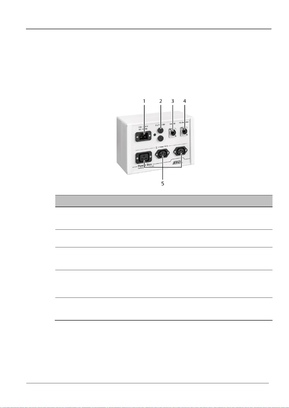
3.4 Power Box (PD-TaD 80 as a standalone system)
The Power Box acts as the power supply for all system components:
PD-TaD 80
VLF HV generator
Laptop
No.
Element
Function
1
Mains voltage
connection
Is used to connect the Power Box to the mains voltage
When the mains voltage is connected, the LED next to the mains voltage
connection lights up.
2
Device protection fuse
Used to protect the Power Box and connected system components
Type: T 16 AH
3
Laptop port
Is used to connect the laptop
The laptop is used for data transmission and is connected to the Power Box
via the Ethernet cable (included in the standard delivery).
4
PD Detector port
Is used to connect the PD measuring unit of the PD-TaD 80
The PD measurement unit is connected to the Power Box via a PoE cable.
The PoE cable is used for the power supply of the PD-TaD 80 and for data
transmission.
5
Ports for system power
supply
Are used to connect the VLF HV generator and the laptop to the power
supply on the Power Box
Max. current 16 A

PD-TaD 80 Product information
822-188-3 19 / 74
3.5 HF filter
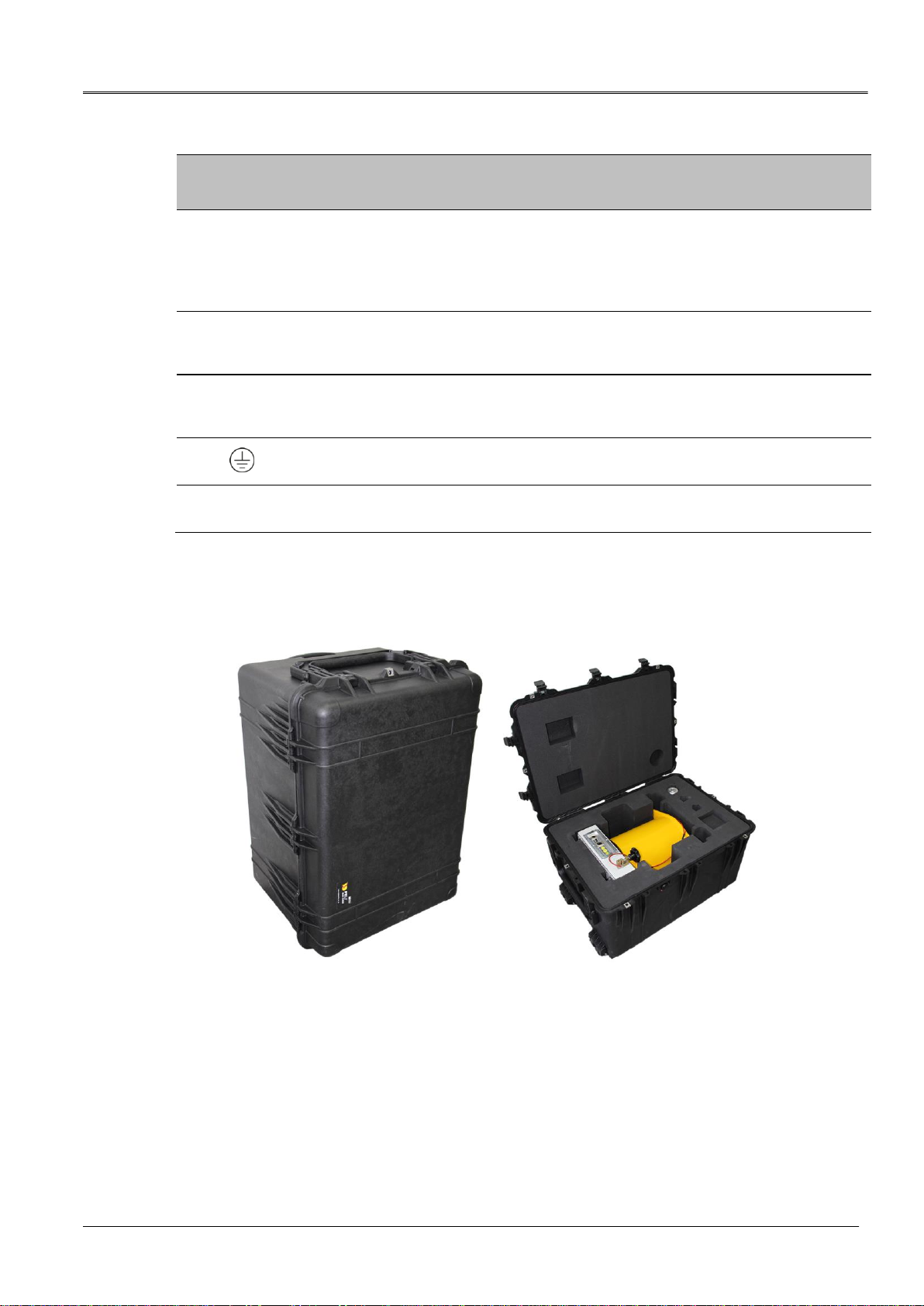
The HF filter is used to minimise external influences on the measurement results. When the
PD-TaD 80 is integrated in the cable test van, the HF filter is stored in drawers. When the
PD-TaD 80 is used as a standalone system, the HF filter is supplied in the PD-TaD 80
transport case.
3.6 Connection set
When the PD-TaD 80 is integrated in the cable test van, the connection set is stored in
drawers. When the PD-TaD 80 is used as a standalone system, the connection set is located
in the transport case. The illustration shows an example of the connection set in the
transport case.
No.
Element
Function
1
VSE cables
Are used for detecting leakage currents during a dissipation factor
measurement
2
Guard rings (conductible
Velcro strips)
Used for the measurement setup for the dissipation factor measurement for
detecting leakage currents
3
Distance pieces for
anti-corona hood
Are used for fitting anti-corona hoods of the anti-corona protection device
4
Connection piece for
HF filter
Is used to connect the HV connection cable of the cable test van or VLF HV
generator to the HF filter
5
HV connection terminal
Is used to connect the HV connection cable to the test object
6
Various fixtures and
fittings
Used to lay and secure the connection cables

Product information PD-TaD 80
20 / 74 822-188-3
No.
Element
Function
7
Anti-corona hoods of the
anti-corona protection
device
Used to protect against corona discharges
8
HV connection cables,
length 0.7 m and 1.2 m
Are used to connect the PD-TaD 80 to the test object
9
Calibrator CAL1B/CAL1E
Is used to calibrate the PD test circuit
10
Power Box
(for standalone systems
only)
Is used for:
Power supply for the system components
Data transmission between the PD-TaD 80 and the laptop
11
Connection cables
Are used to connect the system components and the power supply, and for
data transmission between the system components
Further information: Chapter Connection cables (on page 22)
3.6.1 Calibrator
Before you can perform a partial discharge measurement, the test circuit must be calibrated
to the following parameters:
Charge (in nC)
Cable length or speed of the PD pulses.
The delivered calibrator is connected to the test object for the calibration.
For information on calibrating the PD measurement system, refer to
the user manual for the BAUR software.
Table of contents
Other Baur Diagnostic Equipment manuals


