GF Signet 3-0250 User manual

The 3-0250 USB-to-S3L Configuration/Diagnostic Tool interfaces with various Signet sensors to allow users to modify (all allowable)
parameters available inside the sensor, monitor the sensor's data on the PC/Laptop or to log the sensor's data to a file.
Signet 3-0250 USB-to-S3L Configuration/Diagnostic Tool
*3-0250.090*
3-0250.090 Rev. C 10/12 English
English
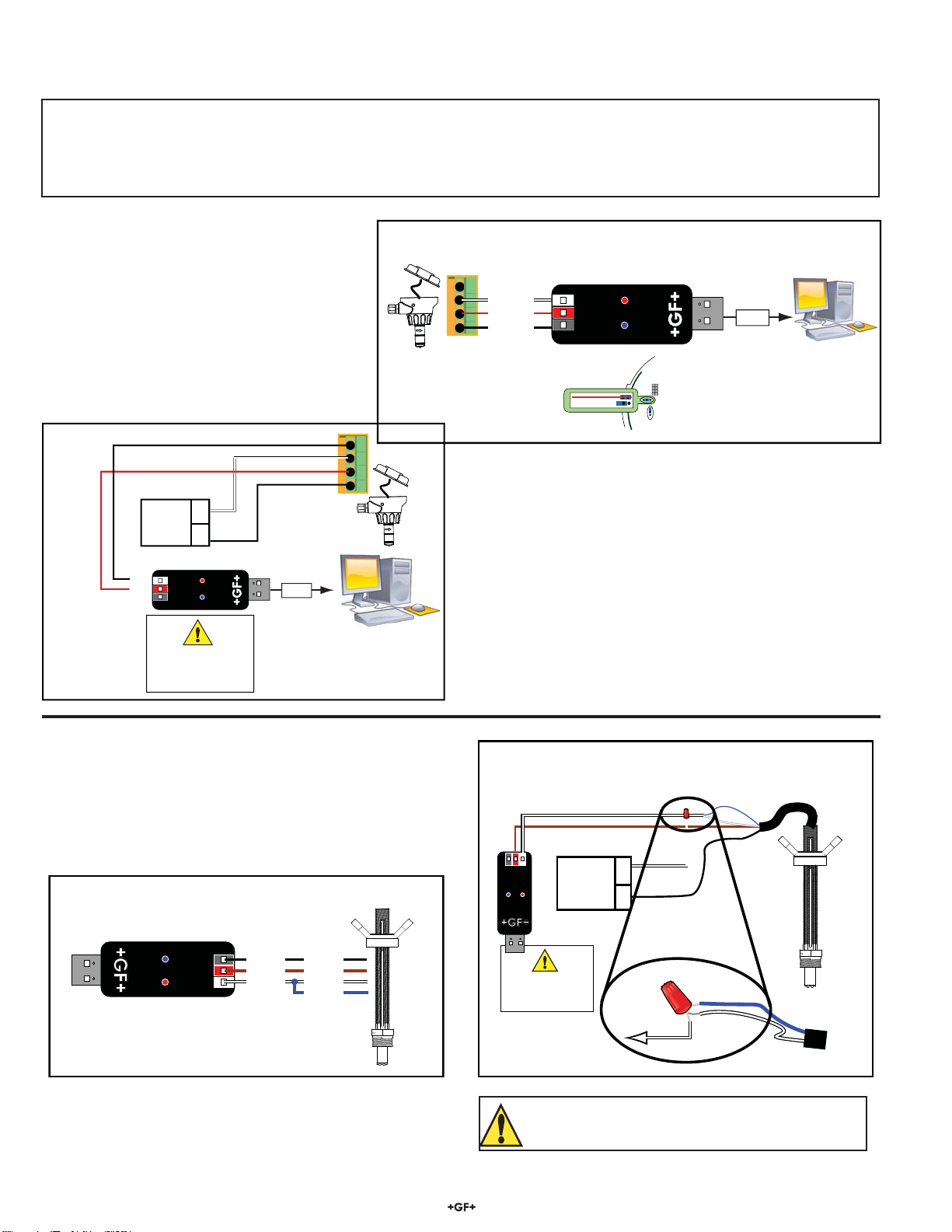
1. Collect the equipment and information that will be required:
• 3-0250 Setup Tool (Includes one USB-S3L Converter with extension cable and one CD-ROM with software)
• 24 VDC ISOLATED power source.
• Personal computer with:
• Intel®Pentium®or higher or AMD 1800 or higher
• Windows®98, 2000, XP, Vista®, 7 or 8 operating systems.
• 40 MB free disk space
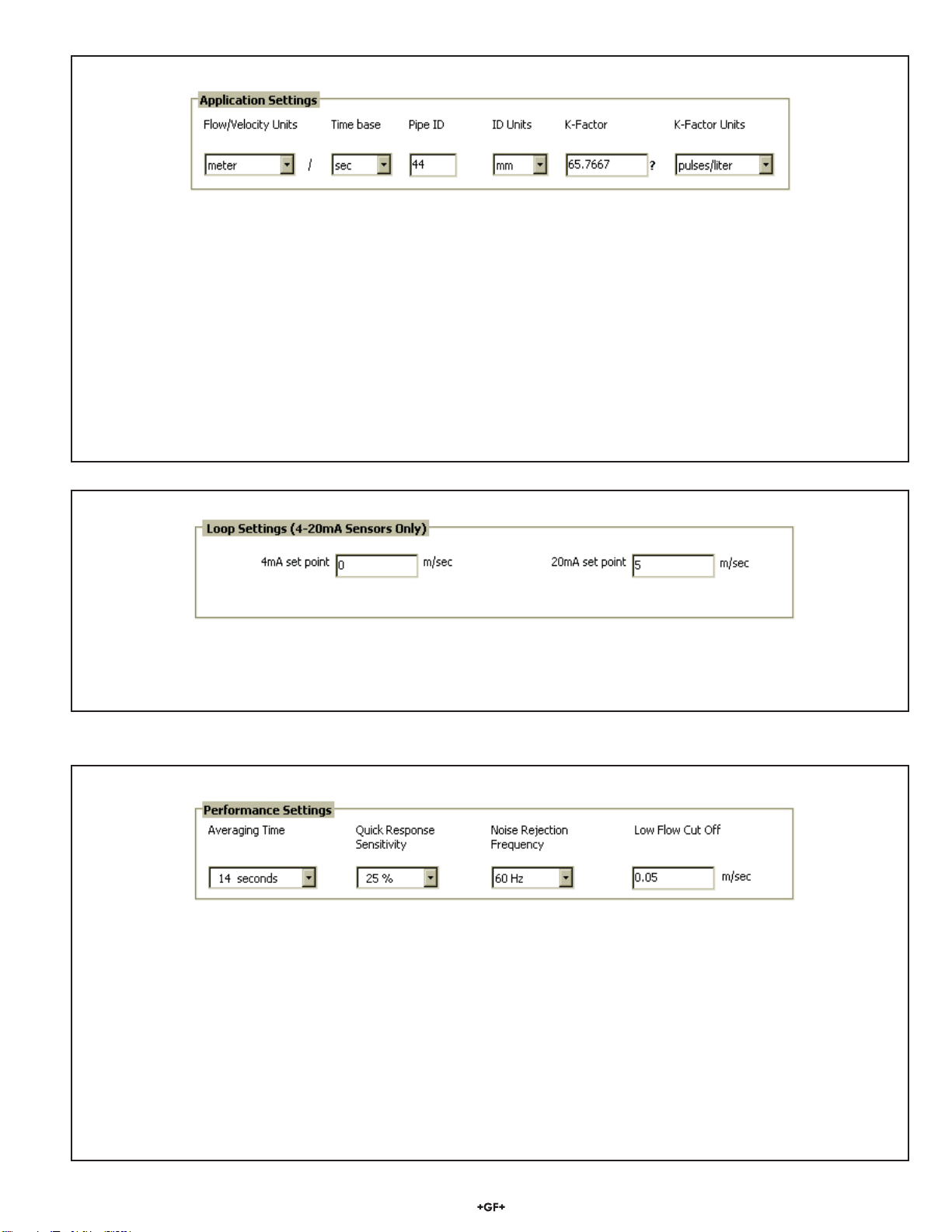
• Application-specific information:
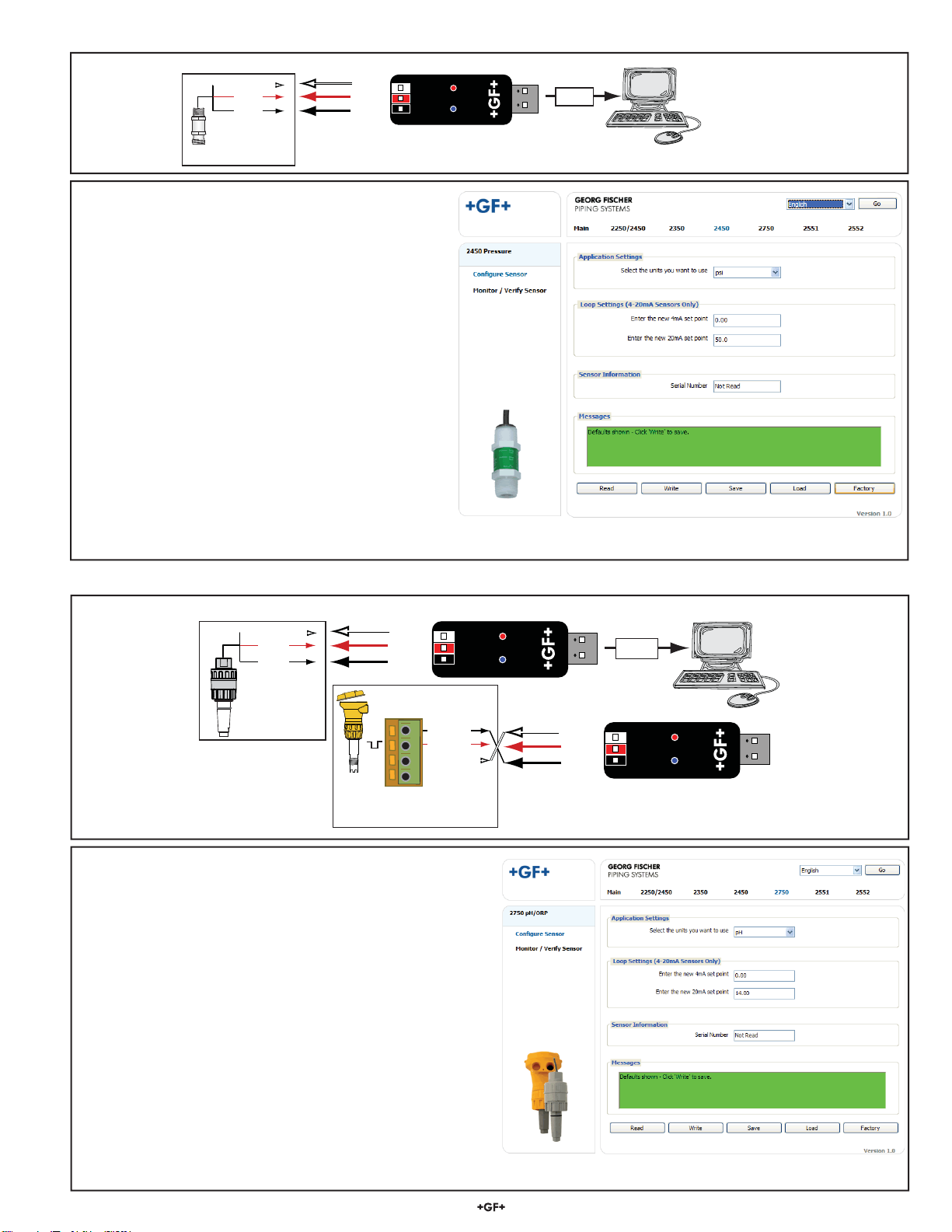
• Pipe data and measurement references for 2551, 2552 (Engineering units, Timebase, Averaging time, Sensitivity, Noise
rejection, Low flow cut off)
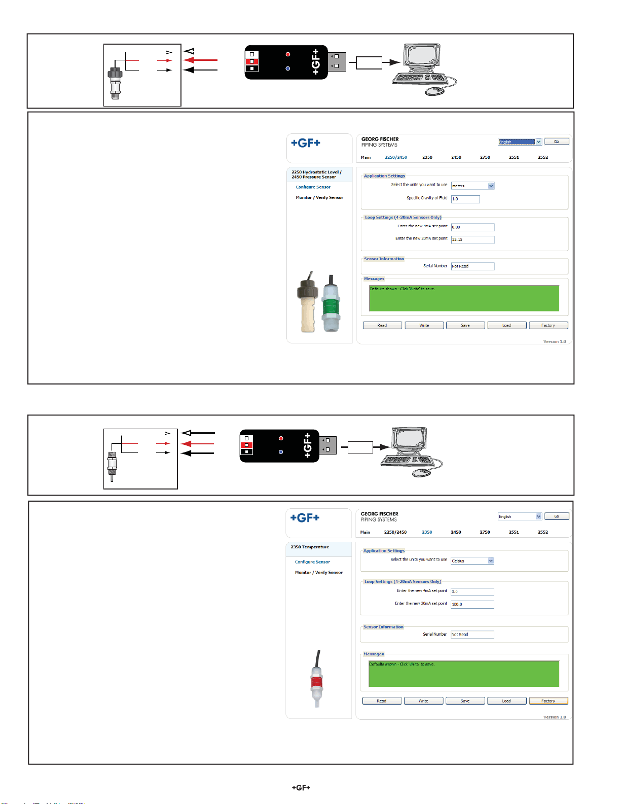
• 4-20 mA span for 2250, 2350, 2450, 2551, 2552, 2750
2. Install the USB driver onto the computer:
• Windows 2000, XP, Vista, 7 or 8 operating system: Insert the CD-ROM into the computer. A Windows Installation Wizard will open to
install the USB driver onto your local hard drive.
• Windows 98 Operating System: READ THIS FILE FOR USB DRIVER INSTRUCTIONS.
Specifications
Compatibility
Signet 2250 Signet 2350 Signet 2450
Signet 2551 Signet 2552 Signet 2750
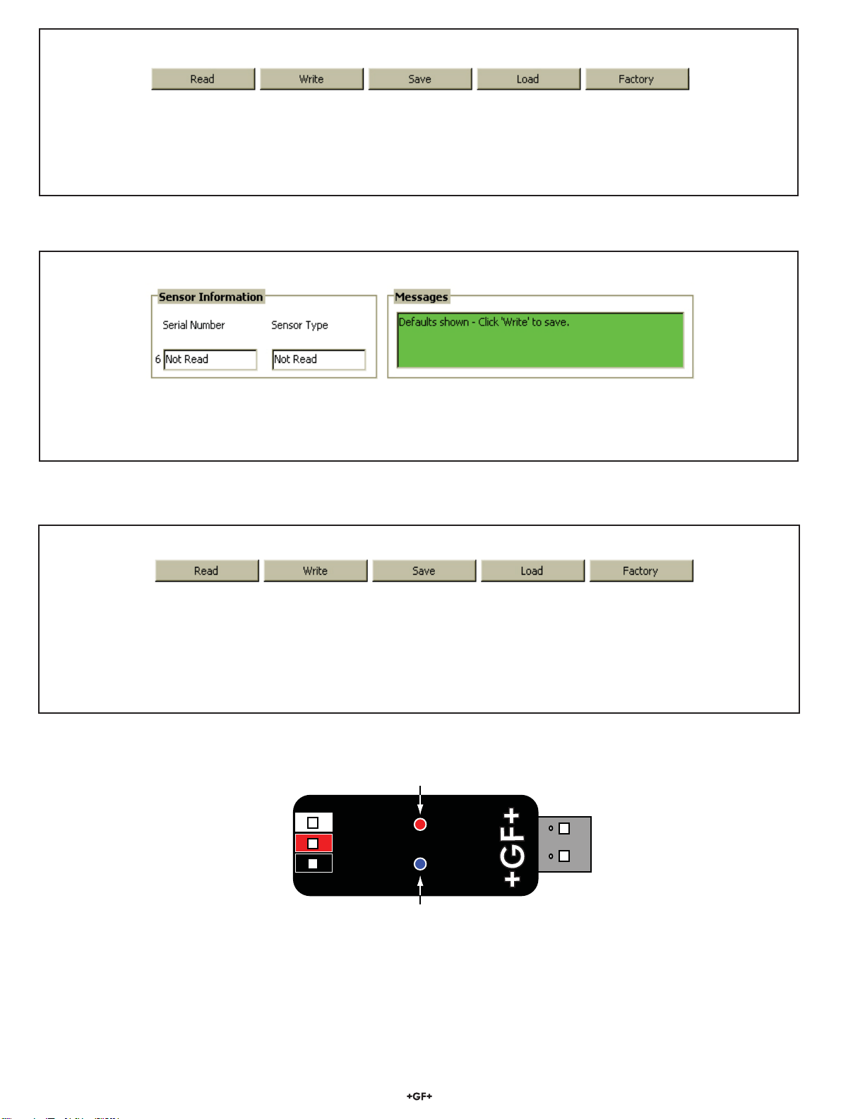
Indicators: Red: POWER ON
Blue: DATA COMMUNICATION
Enclosure: ABS
Input connections: 3-terminal connectors, max 14 AWG
Communication rate: Maximum 19.2 kbs
Input power: Computer USB port
Output power: 5 VDC ± 5%
Power consumption: 5 V @ 15 mA
Maximum current source: 50 mA
Maximum cable: 300 m (1000 ft.)
Storage temperature: -20 to 100 °C (-4 to 212 °F)
Relative Humidity: 0 to 90% non-condensing
Operating Temperature: -15 to 55 °C (5 to 131 °F)
(module only)
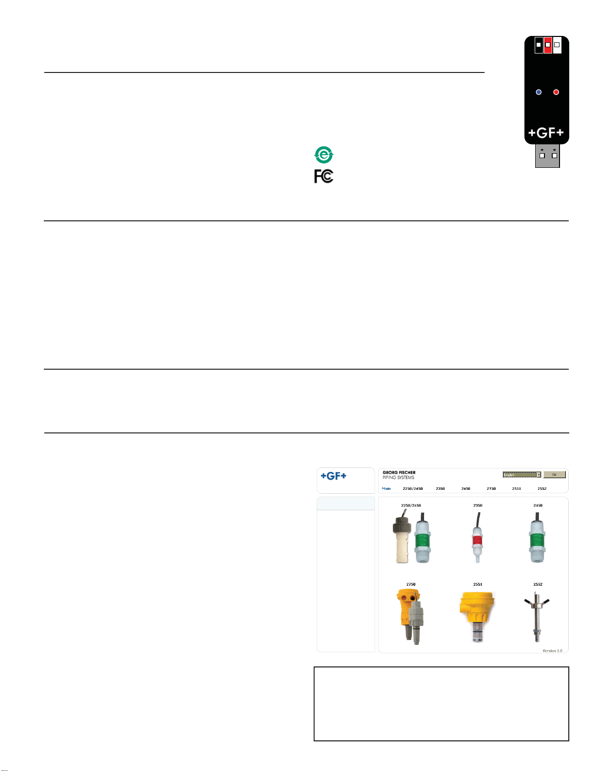
3. To run the program from the CD:
• Right-click the START button and select EXPLORE. Navigate
to the CD drive.
• Double-click the 3-0250.exe file.
• The Setup screen shown here should be on the computer
display.
• Select a language option from the pull-down menu in the upper
right corner.
3a. To run the program from a local hard drive:
• Drag the 3-0250.exe file from the CD to the folder on the hard
drive.
• Drag the 2551Eng.pdf and the 2552Eng.pdf files to the same
folder as the 3-0250.exe file.
• Remove the CD.
• Double-click the 3-0250.exe file to start the program.
• The Setup screen shown here should be on the computer
display.
• Select a language option from the pull-down menu in the upper
right corner.
• Regional computer settings will determine number format
(1.234, 1 234 or 1,234)
• Do not use thousands separator when entering numeric values.
(1234.5, not 1,234.5 or 1 234.5).
• Click on the image of the product to begin. Important:
Managed systems and network systems may have security
measures enabled that block the installation of this program.
See the network administrator or IT (Information Technology)
staff if the program cannot be installed.
Windows and Vista are registered trademarks of the Microsoft Corporation
in the United States and other countries. Intel and Pentium are registered
trademarks of Intel Corporation in the U.S. and/or other countries. AMD is
a trademark of Advanced Micro Devices, Inc.
China RoHS (Go to www.gfsignet.com
for details)
This device complies with Part 15 of the FCC rules.
Operation is subject to the following two conditions:
(1) This device may not cause harmful interference, and,
(2) This device must accept any interference received,
including interference that may cause undesired operation.

2Signet 0250 Setup Tool
Connect the Magmeter to the computer:
• Connect the Magmeter to the 3-0250 as illustrated.
• For 3-2551-11 models: The frequency/digital jumper MUST be in the Digital position.
• Connect the isolated 24 VDC power source to 4-20 mA model Magmeters.
• Connect the Signal Converter to any open USB port on the computer.
CAUTION!
TURN 24 VDC POWER OFF WHEN WIRING THE MAGMETER.
System connections
Signet 2552 Metal Magmeter
System connections
Signet 2551 Blind Magmeter
2551 and 2552 Magmeters
The setup capability of the 0250 is more complex with the magmeters than with other sensors. Read these instructions carefully before
attempting to modify a Magmeter.
CAUTION!
Do not connect power
directly to this device.
White
Blue
Brown
Black
Isolated
24 VDC +
-
White
Blue
Wire Nut
To -VDC
*Wire 1
*Wire 2
*Wire 3
* Additional wire required
Signet 2552
4-20 mA Out
Data
+5 VDC
Ground White
Brown
Black
Blue
Signet 2552
Frequency/S3L Out
1
2
3
4
2551 Blind Magmeter
Frequency/S3L Out
JP2
FREQUENCY OUT
DIGITAL (S L) OUT
3
Freq/Digital jumper
must be in Digital position
GND
Data
5V out+ USB
1
2
3
4
GND
Data
5V out+
Isolated
24 VDC +
-
2551 Blind Magmeter
4-20 mA Out
USB
CAUTION!
Do not connect power
directly to this device.

3
Signet 0250 Setup Tool
Flow/Velocity Units (factory set: Meters)
• Select the engineering units from the list: meters, feet, cubic meters, liters, cu. ft., U.S. gallons, Imp. gallons.
Timebase (factory set: Seconds)
• Set the timebase preference: seconds, minutes, hours, days
Pipe ID (Inside Diameter) (factory set: 44.0)
• Enter the inside diameter of the pipe.
ID Units: (factory set: millimeters)
• Select inches or mm for the dimensions of the pipe.
K-Factor (factory set: 65.7667)
• K-factors are published as "pulses per gallon" and "pulses per liter" in the Magmeter manual.
• Click the "?" to open a copy of the manual (manual file must be placed in the same directory as the 3-0250.exe application file).
K-factor units (factory set: pulses/liter)
• Select pulses/gallon or pulses/liter.
4 mA Setpoint (factory set: 0 m/s)
• Enter the flow rate where the Loop output must equal 4 mA.
20 mA Setpoint (factory set: 5 m/s)
• Enter the flow rate where the Loop output must equal 20 mA.
Averaging Time (Factory set:14 s)
• Set the time the Magmeter will use as the averaging period. Example: With averaging at 14 seconds, each display is an average
of the previous 14 seconds input. Use higher averaging times to smooth the display and current output where the flow in the pipe
is erratic.
Quick Response Sensitivity (Factory set: 25)
• Set the percentage of change in the flow rate required to allow the Magmeter to override the AVERAGING and jump
to a new flow rate immediately. (2551 maximum range is 10 m/s)
A detailed explanation of Averaging and Sensitivity functions is provided on Page 5.
Noise Rejection Frequency (Factory set: 60 Hz)
• Select 50 Hz or 60 Hz according to local AC power specifications.
Low Flow Cut-off (Factory set: 0.05 m/s)
• Set the flow rate where all Magmeter outputs will be forced to zero.
(When the flow rate drops below this value, the frequency output will be 0 Hz. and the current output will be 4 mA.)
2551 and 2552 Magmeter Setup
1. Set the general information about the pipe and application preferences in the Application Settings fields.
2. Set the 4-20 mA span (If applicable)
3. Set the Performance Settings to best accomodate the unique conditions in the pipe.

4Signet 0250 Setup Tool
Serial Number, Sensor Type:
• This sensor information is read from the Magmeter when you press the "Read" button.
Messages:
• Displays messages related to the current selection. Error messages and procedure instructions will appear here.
• To repeat the same settings in another Magmeter, disconnect the Magmeter and connect the second Magmeter.
Note: For 4-20 mA models, remove 24 VDC power before rewiring.)
• Click "Write" again.
Note: All settings are lost when you exit the program. If the settings will be used again, click "SAVE". Name the file and save it on
the computer hard drive.
• Read: Read and display the existing settings from the Magmeter.
• Write: Write from the display into the Magmeter.
• Save: Save from the display to a file (*.bdf).
• Load: Load from a saved file into the display.
• Factory: Restores Application, Loop and Performance settings to original factory values.
Note: The blue LED on the 3-0250 blinks during data communication between the computer and the sensor.
GND
Data
+5V from USB port
Blue LED indicates data transmission
Red LED indicates power
4. Click "Write" to copy the new settings into the Magmeter.
Sensor Information
Controls

5
Signet 0250 Setup Tool
AVERAGING Only
With AVERAGING set to 60 seconds and SENSITIVITY set to
100%, the flow rate is stabilized, but a sharp change in flow rate
is not represented for 60 seconds or longer. This can cause
system problems if one of the operating setpoints falls within this
range.
AVERAGING and SENSITIVITY
With AVERAGING at 60 seconds and SENSITIVITY set to 25%,
the flow rate is stabilized, but the sudden shift in flow is reflected
very quickly.
No AVERAGING, no SENSITIVITY
With AVERAGING set to 0 (zero) the SENSITIVITY is ineffective,
and the flow rate may be very unstable. This will cause the output
signals to respond erratically.
10 s 20 s 30 s 40 s 50 s 60 s 70 s
Time
Velocity
10 s 20 s 30 s 40 s 50 s 60 s 70 s
Time
Velocity
10 s 20 s 30 s 40 s 50 s 60 s 70 s
Time
Velocity
Magmeter Averaging and Sensitivity Settings
Because ideal flow conditions are often impossible to acheive, the flow rate is often erratic, which in turn causes any control features
(ie; relays, 4-20 mA loops, etc.) that are associated with the flow rate to also be erratic.
The best solution to these problems is to correct any piping deficiency that causes the instability. This may involve longer straight runs
upstream, reducing the pipe size to maintain a full pipe at all times, and other installation changes. In many situations, however, these
measures are simply not possible.
The Magmeter provides several tools that are designed to "work around" these deficiencies. They are called "Performance Settings"
and can be modified only through the 3-0250 Setup Tool. The noise rejection and the Low Flow Cutoff settings are self-explanatory. The
Averaging and the Sensitivity features should be studied before making adjustments.
Averaging Time in Seconds (Factory set: 14 seconds)
• Set the time the Magmeter will use as the averaging period.
With averaging at 14 seconds, each display is an average of the previous 14 seconds input.
Use higher averaging times to smooth the display and current output where the flow in the pipe is erratic.
Quick Response Sensitivity (Factory set: 25% of Maximum Range, or 2.5 m/s)
• Set the percentage of change in the flow rate required to allow the Magmeter to override the AVERAGING and jump to a new flow
rate immediately. (maximum range is 10 m/s)
The pictures below illustrate the effect of these settings.

6Signet 0250 Setup Tool
Windows PC
USB
GND
Data
+5V out
Signet 2250
Hydrostatic
Level Sensor
GND
Data
+5V
Signet 2250 Hydrostatic Level Sensor Setup
2250 Wiring
2250 Operation
1. Select the engineering units for the application: inches,
feet, centimeters or meters.
2. Set the Level measurement where the Loop output must
equal 4 mA.
3. Set the Level measurement where the Loop output must
equal 20 mA.
• Minimum setting for both endpoints is 0.
• Maximum setting for both endpoints is based on the
maximum pressure rating of the sensor.
• Maximum setting, -XU sensor (0-10 psi)
• 7.03 m = 703.1 cm = 23.07 ft. = 276.8 in.
• Maximum setting, -XL sensor (0-50 psi)
• 35.15 m = 3515.0 cm = 115.33 ft. = 1384.0 in.
4. Click "Write" to copy settings from the display into the
Magmeter.
Click "Save" to save the settings from the display to a
computer file.
5. To use a saved file:
• Click "Load"
• Navigate to the saved file
• Select Open
• Click "Write"
• Click "Read" to confirm
Signet 2350 Temperature Sensor Setup
Windows PC
Signet 2350
Temperature
Sensor
USB
GND
Data
+5V out
GND
Data
+5V
2350 Wiring
2350 Operation
1. Select the engineering units for the application:
°C (Celsius) or °F (Fahrenheit).
2. Set the Temperature measurement where the Loop output
must equal 4 mA.
• Minimum setting -10 °C (14 °F)
• Maximum setting 100 °C (212 °F)
3. Set the Temperature measurement where the Loop output
must equal 20 mA.
• Minimum setting -10 °C (14 °F)
• Maximum setting 100 °C (212 °F)
4. Click "Write" to copy the settings from the display into the
Magmeter.
OR
Press "Save" to save the settings from the display to a
computer file.
To use a saved file:
• Click "Load"
• Navigate to the saved file
• Select Open
• Click "Write"
• Click "Read" to confirm.

7
Signet 0250 Setup Tool
Signet 2450 Pressure Sensor Setup
Windows PC
Signet 2450
Pressure
Sensor
USB
GND
Data
+5V out
GND
Data
+5V
2450 Wiring
Operation
1. Select the engineering units for the application: kpa, bar
or psi
2. Set the Pressure measurement where the Loop output
must equal 4 mA.
• Minimum setting 0 psi
• Maximum setting 10, 50 or 250 psi
3. Set the Pressure measurement where the Loop output
must equal 20 mA.
• Minimum setting 0 psi
• Maximum setting 10, 50 or 250 psi
4. Click "Write" to copy the settings from the display into the
Magmeter.
• Click "Save" to save the settings from the display to a
computer file.
To use a saved file:
• Click "Load"
• Navigate to the saved file
• Select Open
• Click "Write"
• Click "Read" to confirm
Signet 2750 pH Sensor Setup
2750 Wiring
2750 Operation
1. Select the engineering units for the application: pH or ORP
2. Set the pH or ORP measurement where the Loop output
must equal 4 mA.
• Minimum setting 0 pH, -1000 mV ORP
• Maximum setting 14 pH, 2000 mV ORP
3. Set the pH or ORP measurement where the Loop output
must equal 20 mA.
• Minimum setting 0 pH, -1000 mV ORP
• Maximum setting 14 pH, 2000 mV ORP
4. Click "Write" to copy the settings from the display into the
Magmeter.
• Press "Save" to save the settings from the display to a file.
To use a saved file:
• Click "Load"
• Navigate to the saved file
• Select Open
• Click "Write"
• Click "Read" to confirm.
Windows PC
Signet 2750
pH/ORP
Sensor,
Submersible +5V in
Data
GND
1
2
3
4
+
S
-
Signet 2750 pH/ORP
Sensor, Inline
USB
GND
Data
+5V out
GND
Data
+5V out
GND
Data
+5V

Georg Fischer Signet LLC, 3401 Aero Jet Avenue, El Monte, CA 91731-2882 U.S.A. • Tel. (626) 571-2770 • Fax (626) 573-2057
For Worldwide Sales and Service, visit our website: www.gfsignet.com • Or call (in the U.S.): (800) 854-4090
For the most up-to-date information, please refer to our website at www.gfsignet.com
3-0250.090 Rev. C 10/12 English © Georg Fischer Signet LLC 2012
Datalogger Operation
The 0250 can serve as a field data logger that downloads data directly into a *.csv (Comma Separated Value) file.
Note: The 0250 does NOT have internal memory to store data. It must be connected to a computer to use the datalog function.
• Select the sensor type, click on "Read".
• Click Monitor/Verify Sensor to open a datalog setup window.
• Enter the Logging Interval. This value represents the time between log records.
The minimum interval is 1 second, and the maximum interval is 86400 seconds (24 hours). Example: If the Log Interval is set to
60 seconds, the 0250 will record the temperature once every minute.
• The 0250 saves data files in *.csv format. The maximum number of records allowed for this type of file is 65535.
If the logging interval is 60 seconds, the largest file possible is 65535 records, or 1092 hours of continuous recorded data.
• To initiate a log session click Begin Monitor or Begin Log to File.
Begin Monitor
• This function starts monitoring the sensor output and displays values on a graph, but does not store the data permanently. During
the monitoring session the Begin Log to File and Save Log functions are disabled, while the Pause and End Log functions are
enabled. Save Log enables a monitoring session to be saved immediately after End log is clicked.
Begin Log to File
• This function prompts the user to create a file on a computer drive before it starts monitoring. The system then begins recording the
sensor output and display values on a graph. During a Log-to-file session the Begin Monitor and Save Log functions are disabled,
while the Pause and End Log functions are enabled.
Sample of data file downloaded to Microsoft Excel
Table of contents