Emerson CORESENSE Manual

D7.8.4/0112-0415/E 1/17
Date of last update: Apr-15
Ref: D7.8.4/0112-0415/E
Application Engineering Europe
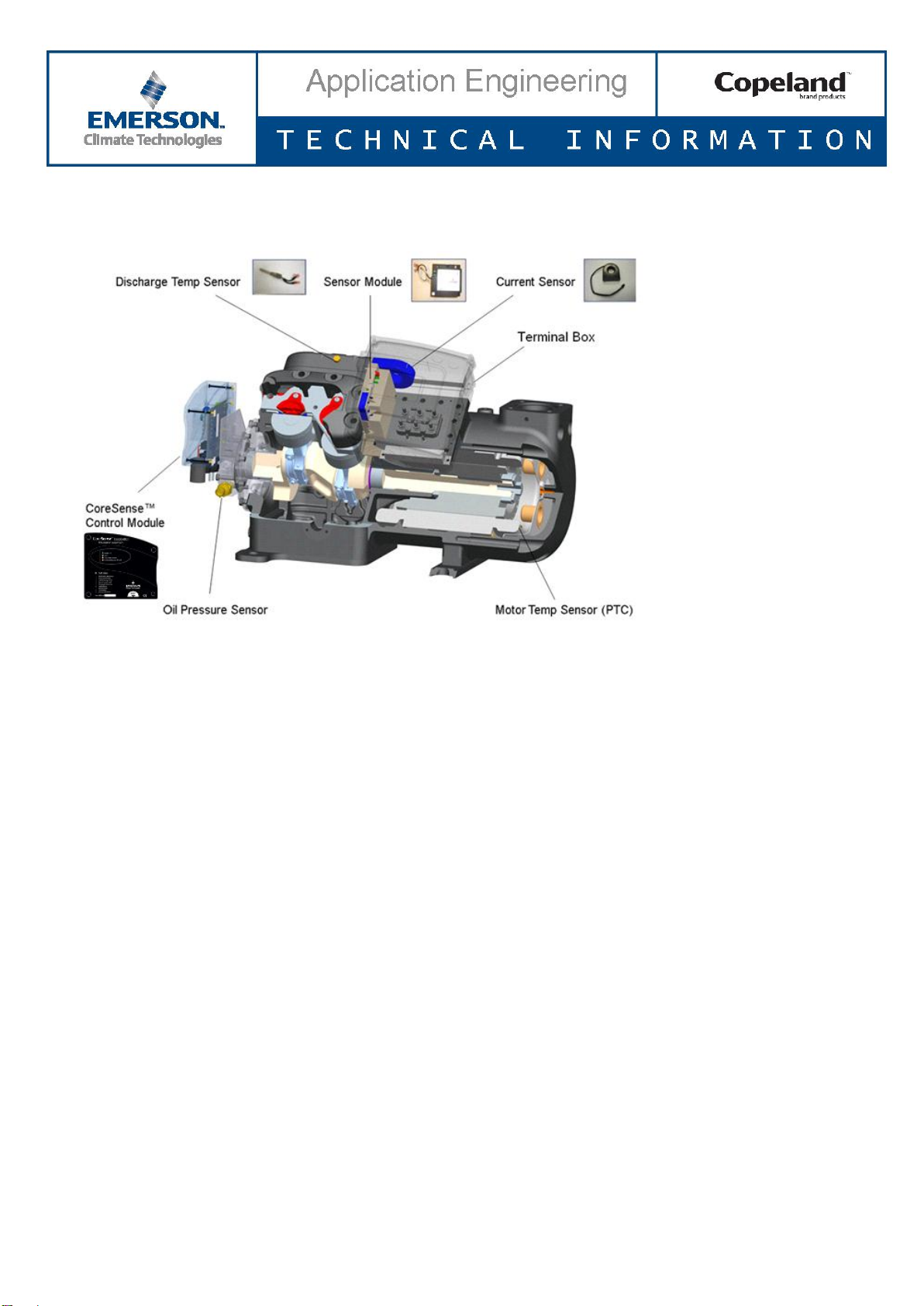
CORESENSE™ DIAGNOSTICS FOR STREAM REFRIGERATION COMPRESSORS
CoreSense™Diagnostics for Stream Refrigeration Compressors................................................................................1
1 Introduction..........................................................................................................................................................2
2 Specifications........................................................................................................................................................2
3 CoreSense Diagnostics features ...........................................................................................................................2
3.1 Insufficient oil pressure protection ..............................................................................................................3
3.2 Motor overheat protection ..........................................................................................................................3
3.3 High discharge temperature protection.......................................................................................................3
3.4 Locked rotor protection................................................................................................................................4
3.5 Missing phase protection .............................................................................................................................4
3.6 Low voltage protection.................................................................................................................................4
3.7 Voltage imbalance protection ......................................................................................................................4
3.8 “Jog” feature.................................................................................................................................................5
3.9 Crankcase heater (CCH) control....................................................................................................................5
3.10 Flash memory information ...........................................................................................................................5
3.11 Modbus® communication.............................................................................................................................6
3.12 Reset .............................................................................................................................................................7
3.13 Alarm history and running conditions ..........................................................................................................7
3.14 Compressor status codes..............................................................................................................................7
3.15 LEDs on the module to display the failure alarms........................................................................................7
3.16 Oil functionality self-test option...................................................................................................................9
4 Electrical connections...........................................................................................................................................9
4.1 System wiring diagram .................................................................................................................................9
4.2 Terminal box and current sensing transformer connections .....................................................................11
4.2.1 Installation of current sensing module...............................................................................................11
4.2.2 CoreSense Diagnostics with Υ/Δmotors ............................................................................................11
4.2.3 CoreSense Diagnostics with part winding ..........................................................................................12
5 CoreSense Diagnostics jumper settings..............................................................................................................13
6 CoreSense Diagnostics DIP-switch settings ........................................................................................................14
7 Troubleshooting..................................................................................................................................................15

D7.8.4/0112-0415/E 2/17
1 Introduction
CoreSense™is an ingredient brand name for compressor electronics associated with Emerson’s Copeland™
brand products. CoreSense technology uses the compressor as a sensor to unlock information from within the
compressor providing value added features such as advanced motor protection, diagnostics, power consumption
measurement and communication.
With active protection, advanced algorithms, and features like fault history and LED indicators, CoreSense
Diagnostics for Copeland brand products compressors enable technicians to diagnose the past and recent state of
the system, allowing for quicker, more accurate diagnostics and less downtime. CoreSense Diagnostics is available
as standard with the 4- and 6-cylinder Stream compressors.
Figure 1: Stream compressor with CoreSense Diagnostics
2 Specifications
Power supply for control module (in front of the compressor) is 120V AC or 240V AC. The sensor module needs
24V AC power supply.
Operating temperature
-32°C to 66°C
Steady load current for relay
3A
Voltage requirements
120V AC or 240V AC
Power rating for the sensor module
3VA
Inrush current for relay
19A
Storage temperature
-40°C to 85°C
Voltage sensor module
24V AC
Protection class
IP54
Table 1
3 CoreSense Diagnostics features
Nr
Feature
Nr
Feature
1
Motor overheat protection
8
Alarm history and compressor operating conditions
2
Insufficient oil pressure protection
9
Crankcase heater control
3
High discharge temperature protection
10
Reset
4
Locked rotor protection
11
Modbus® communication
5
Missing phase protection
12
Power consumption measurement (voltage, current,
power factor)
6
Voltage imbalance protection
13
LEDs on the front module to display the failures
7
Low voltage protection
14
Compressor run status (proofing)
Table 2

D7.8.4/0112-0415/E 3/17
CoreSense is compatible with VFD applications by turning on the DIP-Switch 12 in the front module. The features
available for VFD are limited: motor overheat protection, insufficient oil pressure protection and high discharge
temperature protection. Other features are available in Control Techniques frequency inverters.
Figure 2
3.1 Insufficient oil pressure protection
The CoreSense Diagnostics module replaces the mechanical oil pressure switch. Furthermore, it provides the
added value of communication for insufficient oil pressure warning and lockouts via LED flash codes and/or a
supervisory pack controller. Total insufficient oil pressure time for the compressor is stored and accumulated in the
module memory.
CoreSense Diagnostics will issue a warning when the oil pressure differential falls below 0.48-0.62 bar for
4 seconds.
Once the oil pressure differential falls below 0.48-0.62 bar for 2 minutes (120 sec), the module will shut the
compressor off and a "low oil pressure lockout" will be reported. Before using the reset button, troubleshooting
needs to be done to understand the failure. The compressor will switch back on once the reset has been manually
activated or when power has been cycled to the CoreSense module.
This feature is not applicable to compressor models 4MTL (Stream CO2compressors) as these have no positive oil
pump fitted and are “splash” lubricated.
3.2 Motor overheat protection
Using Positive Temperature Coefficient (PTC) sensors on 4M* and 6M* Stream compressor models, the
CoreSense Diagnostics module provides motor overheating protection. The CoreSense Diagnostics module
replaces the Kriwan module INT69TM.
Alarm conditions:
Trip condition: PTC Resistance > 4.5 kΩ;
Reset condition: PTC Resistance < 2.5 kΩ; 5 min time delay.
3.3 High discharge temperature protection
Discharge temperature protection is provided using a NTC sensor in the compressor cylinder head.
The sensor is pre-installed at the factory and connected to the module. CoreSense will protect the compressor from
high discharge temperature conditions. If the temperature sensor detects a discharge temperature higher than

D7.8.4/0112-0415/E 4/17
154°C, the CoreSense will shut off the compressor until the temperature cools down to an acceptable level (about
130°C).
Either trip or lockout alarm can be selected by user using the PC interface software. Default is trip alarm. Trip and
reset settings are configurable using PC interface software. The configurable range of trip settings is 108°C to
154°C and the reset value is 83°C to 130°C.
Trip/lockout value ≥ 154°C for 2 sec.
Trip alarm: automatic reset after 2 minutes; discharge temp < 130°C.
Lockout alarm: manual reset is necessary.
3.4 Locked rotor protection
CoreSense detects the locked rotor condition of the compressor. It has trip and lockout alarms. Initial alarm will be
“Trip” alarm with autoreset and 10 consecutive trip alarms will result in “Lockout” alarm which requires manual
reset.
3.5 Missing phase protection
If any one of the 3 power phases is missing immediately after the compressor contactor is energized, a single-
phasing condition exists.
The maximum response time shall be 1.2 seconds from the time of contactor energization.
Alarm conditions: Appears in case of missing phase conditions.
Trip time: 5 minutes with automatic reset.
Lockout condition: Appears after the 10 consecutive trip alarms. Manual reset (using reset button below
the module or by cycling the power to the module).
In the case of a part winding motor this feature is detectable for primary winding only. Missing phase, voltage
imbalance and low voltage are not detectable for the secondary winding. A missing phase can be detected during
start-up, but not while the motor is running.
3.6 Low voltage protection
Appears when there is a low supply voltage.
Alarm conditions: Motor compressor voltage < low voltage setting at compressor running state. The default low
voltage setting is 75% of the nominal line voltage stored in the module for 2 seconds.
Trip time: 5 minutes.
The module determines the operating frequency of the compressor. The compressor low voltage setting shall be
lowered by the same percentage as the operating frequency if less than the nominal frequency. For example if a
60 Hz nominal frequency compressor is running at 57 Hz (5% less), then the low voltage setting shall be reduced
by 5%.
3.7 Voltage imbalance protection
The purpose of this feature is to protect the compressor against a voltage imbalance condition that leads to motor
overheating.
A configurable setting (default = 5%) for voltage imbalance is used to determine the operating limit of the
compressor. The voltage imbalance setting is configurable in the range of 2 to 8 % using the PC interface software.
Alarm conditions:
Trip: When the voltage imbalance > 5% (configurable).
Reset: Automatic reset after 5 min; voltage imbalance < 5%.

D7.8.4/0112-0415/E 5/17
3.8 “Jog” feature
The reset button below the control module may be used as an emergency shutdown,
such as for clearing liquid during start-up. After the module re-boots (approximately
3 seconds) the compressor will run again. The reset button may be pushed as necessary
to stop the compressor.
Reset button
Figure 3
3.9 Crankcase heater (CCH) control
The sensor module contains an on-board CCH control relay. An auxiliary contactor is no longer required to turn the
heater on when the compressor turns off.
The appropriate voltage supply to the CCH power input terminals (115V / 230V) is required.
The control of a 480V crankcase heater is not supported by CoreSense Diagnostics.
3.10 Flash memory information
Emerson Climate Technologies can provide software to access EEPROM information.
The following asset information will be saved in the flash memory (EEPROM):
Compressor model number
Compressor serial number
Compressor model number modified
Compressor serial number modified
Compressor nominal voltage and frequency
Sensor module firmware revision
For dual voltage motors the lower value is saved in EEPROM memory. It is advised to change the nominal voltage
setting values to the correct operating voltage in the EEPROM memory using PC interface software. Even if the
nominal voltage is not changed, there is no effect on the compressor functionality due to this setting.
Compressor running status information will be saved in the flash memory (EEPROM):
Number of compressor running hours
Number of compressor starts
Accumulated runtime without good oil pressure
Number of short cycles (compressor starts with a less than 3-minute runtime)
Compressor operating parameters:
Current
Voltage
Power consumption
Discharge temperature values
Crankcase heater
Power supply
Crankcase heater 115V or 230V

D7.8.4/0112-0415/E 6/17
3.11 Modbus® communication
CoreSense Diagnostics has communication capability via a Modbus network connection. With communication
enabled CoreSense warnings, trip and lockout alarms can be displayed and recorded in a pack controller with
Modbus such as the iPro Rack Controller from Dixell.
Two types of Modbus are used with Stream compressors. The only possibility to identify which one is fitted in a
CoreSense module is to open the module lid, and to look at the circuit board and label.
Most of the features are the same; the main differences are explained in Technical information
D7.8.6 “CoreSense™ Diagnostics for Stream Compressors - Modbus® Specification”.
All the pictures and information hereafter deal with the more recent version.
The communication cable is wired from the pack controller to the first compressor. Additional compressors are
wired in a daisy-chained configuration. The last compressor in the daisy chain should be terminated by jumper JP3
in the front module. Please refer to Figures 4 and 5.
Figure 4: RS485 daisy-chain connection Figure 5: Two-rack daisy-chain connection
CoreSense modules can be connected to a PC through the CoreSense PC Interface software. Figure 6 depicts
how to connect the CoreSense Diagnostics module to the PC, using USB to RS485 Dixell adapter.
Communication Port (+ GND –)
Figure 6
Modbus communication in CoreSense allows communication with any other third-party pack controller. The
Emerson E2 controller has –GND + polarity.
The RS485 connection can be removed from the board without switching off the compressor.
For more information on communication with pack controller please contact Application Engineering.
Connect to USB Port

D7.8.4/0112-0415/E 7/17
3.12 Reset
The CoreSense Diagnostics module is equipped with a reset button placed below the control module. The reset
button may be pushed if necessary to reset the alarm conditions.
3.13 Alarm history and running conditions
Operating information
Alarm history
Number of compressor running hours
8 days alarm history
Accumulated running time without good oil pressure
Most recent 10 alarms
Number of short cycles
Total number of alarms since the compressor first
operation
Current, voltage, power consumption measurement*
*This data is not stored in CoreSense EEPROM memory. These values can be stored in a laptop using CoreSense PC Interface
Software or Modbus communication.
Table 3
3.14 Compressor status codes
Steady green: An indication of normal operation. There are no faults or issues with the compressor.
Flashing green: An indication that there is an alert (warning) condition. The compressor can still be
running.
Flashing orange: An indication that the compressor has tripped with auto reset.
Flashing red: An indication that the compressor is in lockout state.
Steady red: An indication that the control module has failed.
3.15 LEDs on the module to display the failure alarms
Two multi-color LEDs on the CoreSense front module display the failure alarms. The LED on the top is green/red
and the LED on the bottom is orange.
For warning/alert (green), trip (orange) and lockout (red), the flash count is defined as 0.1 second ‘On’ and 0.4
second ‘Off’ with a 2-second pause before the flash count repeats (timings are ± 50 ms).
Definitions:
Trip: The module has shut off the compressor due to a fault condition. The compressor will be available to
run again when the fault condition no longer exists, and the minimum off time has been satisfied.
Lockout: The module has shut off the compressor due to a fault condition. The compressor will be
available to run again when the fault condition has been cleared and manual reset has been done.
The QR code located on the
CoreSense cover enables to reach
a Quick Troubleshooting page on
our website.
Figure 7
Alert alarms:
Compressor will not turn off.
Trip alarms:
Compressor turns off for some time
with automatic reset.
Lockout alarms:
Compressor turns off.
Manual reset necessary.

D7.8.4/0112-0415/E 8/17
LED
flashes
count
Status LED description
Auto
reset
time
Lockout
condition
Status LED troubleshooting information
1
Insufficient oil
pressure
N/A
Insufficient
oil pressure
N/A
Without
sufficient oil
pressure for 2
minutes
If flashing green, compressor has been
without sufficient oil pressure for 4 seconds.
If flashing red, compressor has been
without sufficient oil pressure for 2 minutes.
2
N/A
Motor
overheat
trip
N/A
2 min
N/A
If flashing orange, compressor is turned off
because motor temperature has exceeded
set point.
3
High discharge
temp.
High
discharge
temp.
High
discharge
temp.
2 min
Exceeds max
set point
If flashing green, the discharge
temperature probe is open or disconnected.
If flashing orange, discharge temperature
has exceeded set point; compressor is
turned off for 2 minutes before auto
resetting.
If flashing red, discharge temperature has
exceeded set point and the compressor is
locked out.
DLT alarm is configurable as either Trip or
Lockout. Factory default is Trip alarm. DLT
probe is FACTORY INSTALLED
4
Current sensor
fault
N/A
N/A
N/A
N/A
If flashing green, current sensor is
disconnected from the sensor module.
Compressor run state is not known by the
control module.
5
Communication
error
N/A
N/A
N/A
N/A
Communication between control module
and system controller has been lost.
Communication between control module
and sensor module has been lost.
6
N/A
Locked
rotor
Locked
rotor
5 min
10 consecutive
events
If flashing orange, compressor failed to
start, and excessive current may be present
in the compressor. The compressor is
turned off and will remain off for 5 minutes.
If flashing red, compressor failed to start,
and excessive current may be present in
the compressor. The compressor is locked
out after 10 consecutive “Trip” alarm events.
7
N/A
Missing
phase
Missing
phase
5 min
10 consecutive
events
If flashing orange, compressor is turned off
due to missing phase.
If flashing red, the compressor is locked
out after 10 consecutive missing phase trip
alarms.
8
N/A
Low
voltage
Low voltage
5 min
10 consecutive
events
If flashing orange, compressor is turned off
due to low compressor voltage.
If flashing red,the compressor is locked
out after 10 consecutive low voltage trip
alarms.
9
N/A
Voltage
imbalance
N/A
5 min
10 consecutive
events
If flashing orange, compressor is turned off
due to voltage imbalance.
Table 4

D7.8.4/0112-0415/E 9/17
3.16 Oil functionality self-test option
When assembling a Stream compressor at the OEM it is
possible to proceed to an oil functionality test during
production. To enter this test mode simply switch DIP-
switch 11 from Off to On.
This test mode “simulates” current present (or
compressor running). After 2 minutes, the oil pressure
lockout can be observed.
Test mode:
Step 1: Power On / reset module
Step 2: Within 5 seconds, switch DIP-switch 11 from Off to On
Step 3: Low oil pressure warning for 2 minutes followed by low oil pressure lockout (red LED blinking once)
Step 4: Press reset button
4 Electrical connections
4.1 System wiring diagram
Fuses and wire cable sizing must be done in accordance with all applicable electrical code standards. Figure 8
below shows the recommended basic system wiring for a compressor with CoreSense.
Figure 8: Wiring diagram
6th terminal used for grounding

D7.8.4/0112-0415/E 10/17
Figure 9: CoreSense wiring terminals description
Figure 10: Sensor module with current sensor
Power supply crankcase heater Power supply control module
115V or 230V 24V AC
Communication to
CoreSense module
24V AC output
To terminal
plate
Crankcase
heater
Current sensor
Modbus communication port Control module communication
to sensor module
LED Module power
220V or 110V
Contactor
DIP-switch Line
Alarm
Discharge
temperature
sensor
PTC
Oil sensor

D7.8.4/0112-0415/E 11/17
4.2 Terminal box and current sensing transformer connections
Make sure that the black lead from the sensor module is always connected to terminal 2 (factory-installed). Black
lead from sensor module must always be connected to that terminal of which power supply cable is lead through
current sensor.
4.2.1 Installation of current sensing module
One of the motor power leads passes through the “toroid” (current
sensing module). Information from the current sensing module is used
to determine running amps, power consumption and locked rotor
conditions. There are 3 voltage sensing leads attached to the motor
terminals and connected to the sensor module. Two of the leads are
white, and one is black. For proper calculation of power factor and motor
power it is necessary for the black voltage sensing lead and the power
lead through the current sensing module to be connected to the same
motor terminal.
The sensor module needs 3VA (Volt-Ampere) and a 24V AC power
supply. Therefore a Class II transformer must be used. Class II
transformers have a maximum rating of less than 100VA and a
maximum secondary output of 30V AC.
Figure 11: Current sensing module and T-Box wiring
4.2.2 CoreSense Diagnostics with Υ/Δmotors
The terminal box and the current sensing “toroid” connections are
factory-installed. One of the motor power leads must be routed through
the centre opening of the current sensing transformer (see Figures 12 &
13 below).
Figure 12: Current sensing transformer
Figure 13: Wiring sensor module and leads routed through the current sensor

D7.8.4/0112-0415/E 12/17
4.2.3 CoreSense Diagnostics with part winding
If using the CoreSense Diagnostics module with a part-winding start motor, one power lead of each of the windings
should be passed through the current sensing transformer in the same direction (see Figures 14 & 15) to provide
accurate compressor proofing. If the leads (L2 and L8 in picture below) are not routed in the same direction, the
running current may indicate close to zero.
Legend
A4........Sensor module K1....... Contactor M1
A5........Terminal box compressor K4....... Contactor M1 for second part winding
CCH ....Crankcase heater M21..... Fan motor/condenser
F6........Fuse for control circuit R2....... Crankcase heater
F7........Fuse for control circuit Y21..... Solenoid valve capacity control 1
F8........Fuse for control circuit Y22..... Solenoid valve capacity control 2
F10......Thermal protection switch M21
Figure 14: Wiring part winding

D7.8.4/0112-0415/E 13/17
Figure 15: Wiring sensor module and leads routed through the current sensor
5 CoreSense Diagnostics jumper settings
The last compressor in the daisy-chain must be “terminated” by moving the JP3 jumper from “2-3”to “1-2”. For all
other compressors the jumper should remain in the default “2-3”position.
JP4 factory setting is “1-2” (2 Stop Bits). Depending on the Modbus parameters, it can be switched to position “2-3”
(1 Stop Bits).
Do not remove JP1. This is reserved for future use.
Figure 16: CoreSense circuit board

D7.8.4/0112-0415/E 14/17
6 CoreSense Diagnostics DIP-switch settings
Figure 17: CoreSense Diagnostics DIP-switch
DIP-
switch
Factory
setting
DIP-switch function
1
On
Node address for communication
2
Off
Node address for communication
3
Off
Node address for communication
4
Off
Node address for communication
5
Off
Node address for communication
6
Off
Node address for communication
7
Off
Communications Baud rate
Off: 19200 Baud
On: 9600 Baud
8
Off
Off: No parity
On: Even parity
9
Off
Off: Stand-alone mode
On: Network mode
10
On
On: DLT enabled
Off: DLT disabled
11
TBD
Self-test function for oil functionality
12
Off
On: VFD application
Off: Non VFD application
Table 5: CoreSense Diagnostics DIP-switch setting
If you use CoreSense communication, assign a unique node address to each CoreSense Diagnostics module using
switches 1 through 6.
a. Set the communications baud rate for the module using switch 7. “Off” = 19200 baud, “On” = 9600 baud.
The baud rate for each module should be set to match the pack controller.
b. Set switch 8 to “Off” for no parity, to “On” for even parity.
c. Set switch 9 to “Off” for stand-alone mode, to “On” for network mode. Network mode will generate a
communications error if the pack controller fails to communicate with the device. For stand-alone mode, no
communications are expected so the communication error is blocked.
d. Factory default setting is “On”for DIP-switch 10, ie, discharge temperature protection. If you want to
disconnect the discharge temperature sensor, turn off DIP-switch 10.
Push the reset button after changing the switch settings.
Ensure that the DIP-switch settings on each module match the settings for the selected controller communication
port.

D7.8.4/0112-0415/E 15/17
7 Troubleshooting
Flash
code
Alarm conditions
Possible failure reasons
Troubleshooting measures
1
Insufficient oil
pressure
Alert: Appears when the differential
oil pressure is less than 0.48 –0.62
bar for 4 seconds.
Lockout: Appears when the
differential oil pressure is less than
0.48 –0.62 bar for 2 minutes
continuous or intermittent but
determined to be unsafe.
Loose wiring connections
between CoreSense module
and oil sensor.
Faulty oil sensor (missing O-
ring or clogged sensor
screen).
Faulty oil pump.
Clogged strainer screen or
worn bearings.
Check the oil level present in the sight glass. If the oil is not present, resolve
reservoir oil supply problem or oil level control setting issues.
Check that the harness is fully engaged to the sensor.
Measure oil pump differential pressure. If less than 0.48 to 0.62 bar, inspect for
clogged oil screen, faulty oil pump, liquid floodback or worn bearings.
If good oil pressure exists, measure resistance across the oil sensor while the
compressor runs. If the sensor resistance is "open" inspect for clogged sensor
screen or missing O-ring.
If sensor resistance is "closed", temporarily jumper across the harness connector
pins (do not damage the pins!) while the compressor runs. If the oil warning does
not go away, check harness connector engagement at the module circuit board.
2
Motor overheat
Trip: Appears when the motor is
overheated.
Motor rotor is mechanically
seized.
Open circuit in harness.
Connector pin not engaging
at connector on control
module.
Faulty CoreSense module.
In case of trip alarm, allow the motor to cool down for a minimum of 2 minutes (it
may take longer) and the compressor will start automatically.
If resistance is low, inspect for loose terminal strip connections, harness
connection failure at circuit board, open harness circuit or high motor temp due
to return gas temperature, motor voltage or load condition.
3
Discharge temp
protection
Alert: Appears when the discharge
temperature sensor is defective or
disconnected.
Trip/Lockout: Appears when the
discharge temperature is > 154°C for
2 seconds.
Open discharge probe
(faulty).
The probe connection has
not been made to the
harness connector.
The connector is not plugged
into the CoreSense circuit
board.
The discharge temperature
has exceeded the maximum
limit 154°C.
Blocked condenser.
Possible loss of refrigerant.
If there is an alert, check proper probe connection to the harness and proper
harness connection into the circuit board.
If there is an alert, unplug the discharge temp probe and check if the resistance
of the probe is as specified vs its approximate ambient temperature.
If the probe resistance is correct inspect the harness connector receptacle for
damage and apply NyoGel 760G connector lubricant.
Trip or Lockout: resolve system issues (high superheat, high head pressure),
inspect for mechanical damage that can lead to high temps (valve plate gasket,
suction or discharge valve failure).

D7.8.4/0112-0415/E 16/17
Flash
code
Alarm conditions
Possible failure reasons
Troubleshooting measures
4
Connection lost
between sensor
module and
current sensor
Alert: Appears when the signal from
current sensor is not communicated
to the sensor module.
The current sensor is not
connected to the sensor
module.
Faulty current sensor.
Faulty sensor module.
Check if the CT connector is connected to the sensor module. If not connect the
4-pin current sensor connector into the sensor module.
Check if there is continuity between pin 3 & 4 (closest to the latch) of the current
sensing connector. The resistance should be less than 1 Ω. If the resistance is
greater than 1 Ω, replace the current sensing module. Be certain that the
receptacles are fully engaged in the connector block.
Check if the Amp and Volts values are correctly displayed. If not, inspect the
wire harness connector to ensure that the pins are fully engaged.
If the above-mentioned trouble shooting measures did not give positive results,
the reason is mis-installed connector or faulty sensor module. Replace the
faulty sensor module with new one.
5
Communication
error
Alert: Appears when there is no
communication between control
module and sensor module or pack
controller
Communication between
CoreSense control module
and pack controller has been
lost.
Communication between
CoreSense control module
and sensor module has been
lost.
Is there a communication network? If not, set the network dip-switch to "stand-
alone" and press reset.
Is there a communication network? If not, check that the communication
harness is engaged at both the CoreSense module and the sensor module.
If the LED on the top edge of the sensor module is dark, check 24 VAC power
to the sensor module, or replace the sensor module.
If communication network amber light is continuously on, reverse the
communication wire polarity. If voltage between centre pin and the right or left
pin is not 2.3-2.6 VDC, inspect for communication wire failure or wire strands
that are "shorting" between the wires or to ground.
6
Locked rotor
Trip: Appears when excessive current
is present in the compressor. Refer to
AE bulletin for more details.
Lockout: Appears when 10
consecutive locked rotor trip alarms
occur.
Motor rotor is mechanically
seized. Excessive current
present in the compressor.
Damaged valve plates in
cylinder head.
Check that motor voltage is adequate (± 10% of nominal rated voltage),
especially during the starting event.
Start compressor with no load. If it does start with no load, inspect the valve
plate(s) for damage or look for other causes of leak-back.
7
Missing phase
Trip: Appears when there is a missing
phase / single phasing.
Lockout: Appears when 10
consecutive missing phase trip
alarms occur.
Loose wiring connections at
the terminals inside
compressor T-Box.
Worn out contactors.
Line break in one of the
phases.
Check voltage supply from the main power buss.
Check voltage into and out of contactor. Repair or replace contactor if
necessary.
Check that motor electrical connections are tight at the compressor motor
terminals.

D7.8.4/0112-0415/E 17/17
Flash
code
Alarm conditions
Possible failure reasons
Troubleshooting measures
8
Low voltage
Trip: Appears when there is a low
compressor voltage.
Lockout: Appears when 10
consecutive low voltage trip alarms
occur.
Supply voltage is not in the
specified range.
Loose wiring connections at
the terminal plate.
Worn out contactors.
Faults with other peripheral
electrical loads.
Check voltage supply from the main buss.
Check voltage into and out of contactor. Repair or replace contactor if
necessary.
Measure voltage at the compressor terminal.
Check that motor electrical connections are tight at the compressor.
Check that there are not any faults with other peripheral electrical loads (for
example fan motors).
9
Voltage
imbalance
Trip: Appears when the voltage
imbalance value exceeds the set
value (default 5%).
Loose wiring connections at
the compressor terminal plate
inside T-Box.
Worn out contactors.
Faults with other peripheral
electrical loads.
Single phasing conditions.
Check voltage supply from the main buss.
Check voltage into and out of contactor. Repair or replace contactor if
necessary.
Measure voltage at the compressor terminal.
Check that motor electrical connections are tight at the compressor.
Check that there are not any faults with other peripheral electrical loads (for
example fan motors).
Information in this document is subject to change without notice.
Other manuals for CORESENSE
2
Table of contents
Other Emerson Diagnostic Equipment manuals