Draper FCR-701 User manual

These instructions accompanying the product are the original instructions. This document is part of the product,
keep it for the life of the product passing it on to any subsequent holder of the product. Read all these
instructions before assembling, operating or maintaining this product.
This manual has been compiled by Draper Tools describing the purpose for which the product has been
designed, and contains all the necessary information to ensure its correct and safe use. By following all the
general safety instructions contained in this manual, it will ensure both product and operator safety, together
with longer life of the product itself.
AlI photographs and drawings in this manual are supplied by Draper Tools to help illustrate the operation of the
product.
Whilst every effort has been made to ensure the accuracy of information contained in this manual, the Draper
Tools policy of continuous improvement determines the right to make modifications without prior warning.
12045
�
EOBD & OIL
RESET TOOL

1. TITLE PAGE
1.1 INTRODUCTION:
USER MANUAL FOR: EOBD & Oil Reset Tool
Stock No: 12045
Part No: FCR-701
As our user manuals are continually updated, users should make sure that they use
the very latest version.
Downloads are available from: http://drapertools.com/manuals
Draper Tools Limited
Hursley Road
Chandler’s Ford
Eastleigh
Hampshire
SO53 1YF
UK
Website: drapertools.com
Diagnostic helpline: +44 (0) 330 0552100
1.3 UNDERSTANDING THIS MANUALS SAFETY CONTENT:
WARNING! – Information that draws attention to the risk of injury or death.
CAUTION! – Information that draws attention to the risk of damage to the product or
surroundings.
1.4 COPYRIGHT © NOTICE:
Copyright © Draper Tools Limited.
Permission is granted to reproduce this publication for personal and educational use
only. Commercial copying, redistribution, hiring or lending is prohibited.
No part of this publication may be stored in a retrieval system or transmitted in any
other form or means without written permission from Draper Tools Limited.
In all cases this copyright notice must remain intact.
1.2 REVISIONS:
Date first published May 2018.
- 2 -

1. TITLE PAGE
1.1 INTRODUCTION..........................................................................................................2
1.2 REVISION HISTORY ..................................................................................................2
1.3 UNDERSTANDING THIS MANUAL .............................................................................2
1.4 COPYRIGHT NOTICE ................................................................................................. 2
2. CONTENTS
2.1 CONTENTS .................................................................................................................... 3
3. GUARANTEE
3.1 GUARANTEE ...............................................................................................................4
4. INTRODUCTION
4.1 SCOPE.........................................................................................................................5
4.2 SPECIFICATION ..........................................................................................................5
4.3 HANDLING AND STORAGE........................................................................................ 5
5. HEALTH AND SAFETY INFORMATION
5.1 GENERAL SAFETY INSTRUCTIONS .........................................................................6
5.2 SPECIFIC SAFETY INSTRUCTIONS.......................................................................... 6
6. TECHNICAL DESCRIPTION
6.1 IDENTIFICATION ......................................................................................................... 7
7. UNPACKING AND CHECKING
7.1 PACKAGING ...............................................................................................................8
7.2 WHAT’S IN THE BOX?.................................................................................................8
8. PREPARATION & CONNECTIONS
8.1 PREPARATION ...........................................................................................................9
8.2 VEHICLE CONNECTION.............................................................................................9
9. REGISTER & UPDATE
9.1 PREREQUISITE CONDITIONS ................................................................................ 10
9.2 METHOD 1 : VIA TF CARD (RECOMMENDED) ..................................................10-11
9.3 METHOD 2: VIA USB CABLE.................................................................................... 12
10. MAIN MENU SCREEN
10.1 FUNCTIONS ..............................................................................................................13
11. CHANGE LANGUAGE ............................................................................................................13
12. START DIAGNOSTICS
12.1 DIAGNOSIS FLOWCHART OF VEHICLE SYSTEM .................................................13
13. DISPOSAL
13.1 DISPOSAL .................................................................................................................. 14
DECLARATION OF CONFORMITY .............................................................................. ENCLOSED
2. CONTENTS
- 3 -

3. GUARANTEE
3.1 GUARANTEE
Draper tools have been carefully tested and inspected before shipment and are guaranteed to be
free from defective materials and workmanship.
Should the tool develop a fault, please return the complete tool to your nearest distributor or
contact:
Draper Tools Limited, Chandler's Ford, Eastleigh, Hampshire, SO53 1YF. England.
Telephone Sales Desk: (023) 8049 4333 or:
Diagnostic Helpline: +44 (0) 330 0552100.
A proof of purchase must be provided.
If upon inspection it is found that the fault occurring is due to defective materials or workmanship,
repairs will be carried out free of charge. This guarantee period covering parts/labour is 12 months
from the date of purchase except where tools are hired out when the guarantee period is 90 days
from the date of purchase. The guarantee is extended to 24 months for parts only. This guarantee
does not apply to normal wear and tear, nor does it cover any damage caused by misuse, careless
or unsafe handling, alterations, accidents, or repairs attempted or made by any personnel other
than the authorised Draper warranty repair agent.
Note: If the tool is found not to be within the terms of warranty, repairs and carriage charges will be
quoted and made accordingly.
This guarantee applies in lieu of any other guarantee expressed or implied and variations of its
terms are not authorised.
Your Draper guarantee is not effective unless you can produce upon request a dated receipt or
invoice to verify your proof of purchase within the guarantee period.
Please note that this guarantee is an additional benefit and does not affect your statutory rights.
Draper Tools Limited.
- 4 -

4. INTRODUCTION
4.1 SCOPE
A multipurpose EOBD code reader and service tool used for basic diagnostic and service function
resets. Any other application is considered misuse.
4.2 SPECIFICATION
Stock No’s. ............................................................................................................................... 12045
Part No’s. ........................................................................................................................... FCR-701
Rated input .................................................................................................................. 12V 0.15A
Multilingual support .................................................................... English, French, Spanish, German.
Weight .................................................................................................................................. 0.298kg
Note: Draper Tools accepts no responsibility for any
accident or injury arising from servicing the vehicles
system. When interpreting results from the vehicle, always
follow the manufacturer’s recommendation for repair.
- 5 -

5. HEALTH AND SAFETY INFORMATION
5.1 GENERAL SAFETY INSTRUCTIONS
For your own safety and the safety of others, and to prevent damage to the equipment and
vehicles, read the full online manual at drapertools.com thoroughly before operating your scanner.
The safety messages presented below and throughout this user’s manual are reminders to the
operator to exercise extreme care when using this device. Always refer to and follow safety
messages and test procedures provided by vehicle manufacturer. Read, understand and follow all
safety messages and instructions in the full online manual.
Safety Message Conventions Used
We provide safety messages to help prevent personal injury and equipment damage. Below are
signal words we used to indicate the hazard level in a condition.
Indicates an imminently hazardous situation which, if not avoided, will result in death or serious
injury to the operator or to bystanders.
Indicates a potentially hazardous situation which, if not avoided, could result in death or serious
injury to the operator or to bystanders.
Indicates a potentially hazardous situation which, if not avoided, may result in moderate or minor
injury to the operator or to bystanders.
5.2 SPECIFIC SAFETY INSTRUCTIONS
Always use your scanner as described in the manual, and follow all safety messages.
Do not route the test cable in a manner that would interfere with driving controls.
Do not exceed voltage limits between inputs specified in this user’s manual.
Always wear approved goggles to protect your eyes from propelled objects as well as hot or
caustic liquids.
Fuel, oil vapours, hot steam, hot toxic exhaust gases, acid, refrigerant and other debris produced
by a malfunctioning engine can cause serious injury or death. Do not use the scanner in areas
where explosive vapour may collect, such as in below-ground pits, confined areas, or areas that
are less than 18 inches (45 cm) above the floor.
Do not smoke, strike a match, or cause a spark near the vehicle while testing and keep all sparks,
heated items and open flames away from the battery and fuel / fuel vapours as they are highly
flammable.
Keep a dry chemical fire extinguisher suitable for gasoline, chemical and electrical fires in work
area.
Always be aware of rotating parts that move at high speed when an engine is running and keep a
safe distance from these parts as well as other potentially moving objects to avoid serious injury.
Do not touch engine components that get very hot when an engine is running to avoid severe
burns.
Block drive wheels before testing with engine running. Put the transmission in park (for automatic
transmission) or neutral (for manual transmission). And never leave a running engine unattended.
Do not wear jewellery or loose fitting clothing when working on engine.
!
DANGER
!
WARNING
!
WARNING
!
CAUTION
- 6 -
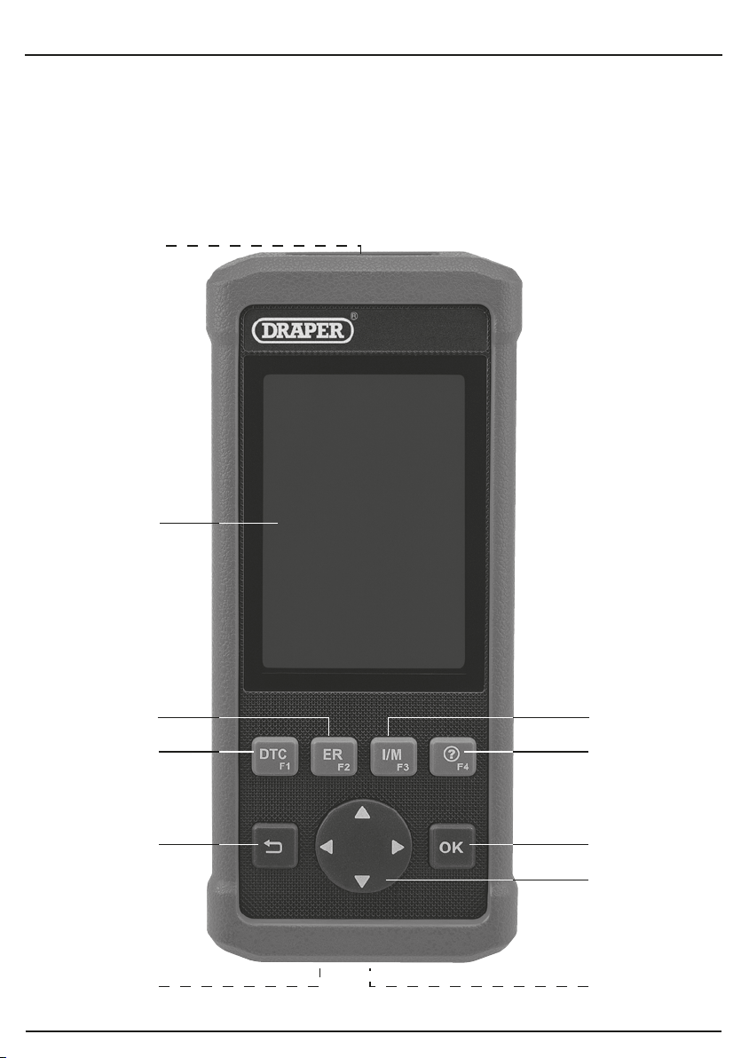
6. TECHNICAL DESCRIPTION
6.1 IDENTIFICATION
(1) Scart connection.
(2) LCD screen.
(3) Erase button.
(4) DTC (Digital Trouble Codes) button.
(5) Back to previous screen button.
(6) Micro SD card slot.
(7) USB Port.
(8) Selection and advance button.
(9) OK button.
(10) Help button.
(11) I/M (Inspection Maintenance) button.
(1)
(2)
(4)
(3)
(5)
(6)
(9)
(8)
(7)
(10)
(11)
- 7 -

7. UNPACKING AND CHECKING
7.1 PACKAGING
Carefully remove the machine from the packaging and examine it for any sign of damage that may
have happened during shipping. Lay the contents out and check them against the parts shown
below. If any part is damaged or missing; please contact the Draper Helpline (the telephone
number appears on the Title page) and do not attempt to use the machine.
The packaging material should be retained at least during the guarantee period: in case the
machine needs to be returned for repair.
Warning! Some of the packaging materials used may be harmful to children. Do not leave any of
these materials in the reach of children.
If any of the packaging is to be thrown away, make sure they are disposed of correctly; according
to local regulations.
7.2 WHAT´S IN THE BOX?
The packaging contains several parts. Lay out the contents and check off the items against those
featured below.
(12) Carry case.
(13) Diagnostic cable.
(14) USB 2.0 cable.
(15) SD card holder.
(12)
(13)
(14)
(15)
- 8 -

8. PREPARATION & CONNECTIONS
Note: To make sure the tool is running the latest available software. it is advisable to check for
updates on a frequent basis. Refer to "Register & Update" for details.
8.1 PREPARATION
• Turn the vehicle ignition on.
• Vehicle battery voltage range should be 9-14Volts.
• Throttle should be in a closed position.
8.2 VEHICLE CONNECTION
1. Locate vehicle's DLC socket: The DLC (Diagnostic Link Connector) is typically a standard
16-pin connector where diagnostic code readers interface with a vehicle's on-board computer.
It is usually located 12 inches from the centre of the steering wheel, under or around the
driver's side for most vehicles.
If the DLC cannot be found, refer to the vehicle's service manual for the location.
2. Connect the diagnostic cable into the vehicle's DLC socket.
3. Plug the other end of diagnostic cable into the diagnostic socket of the handset and tighten the
captive screws.
- 9 -
9. REGISTER & UPDATE
9.1 PREREQUISITE CONDITIONS:
1. Go to http://www.dbscar.com to download the update tool and install it on the computer.
2. System requirements : Windows XP, 7, 8 or Windows 10.
There are 2 methods available to update your tool. You may choose one of the following to
proceed .
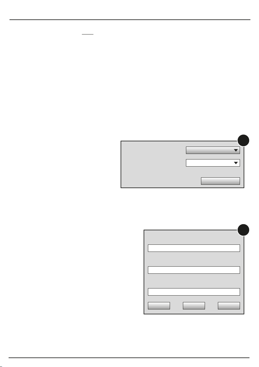
9.2 METHOD 1: VIA TF CARD (RECOMMENDED)
1. Launch the update tool, a screen similar to Fig.1 will appear:
NOTE: The TF CARD should NOT be reformatted at any point.
This will remove all information including product serial number and register code.
If this is to happen:
1. Remove TR CARD.
2. Power unit on, the serial number and register code will display for a few seconds, capture this
information to restore system.
2. In Fig.1 type in the Product Serial Number (located at the back of the tool).
NOTE: Once the S/N is entered, "Restore System" becomes activated, which is used to restore
system if a new TF card is replaced.
3. Click [Device Upgrade] to enter the sign-up page.
Enter the information and click [Submit]
(refer to Fig. 2).
(If you need the Register Code,
please refer to steps 4~7.)
(If you have the Register Code,
directly proceed to step 8.)
Select Language
Product Serial Number
Device Upgrade
English
Your E-mail address:
Confirm E-mail:
Register Code:
Cancel Submit Exit
1
2
- 10 -
9. REGISTER & UPDATE
4. The Register Code can be found in your tool. Connect
one end of the USB cable to your tool, and the other end
on the computer.
5. After the tool has powered up and entered the main
menu screen, move the highlight bar on the "Help" icon
and press [OK].
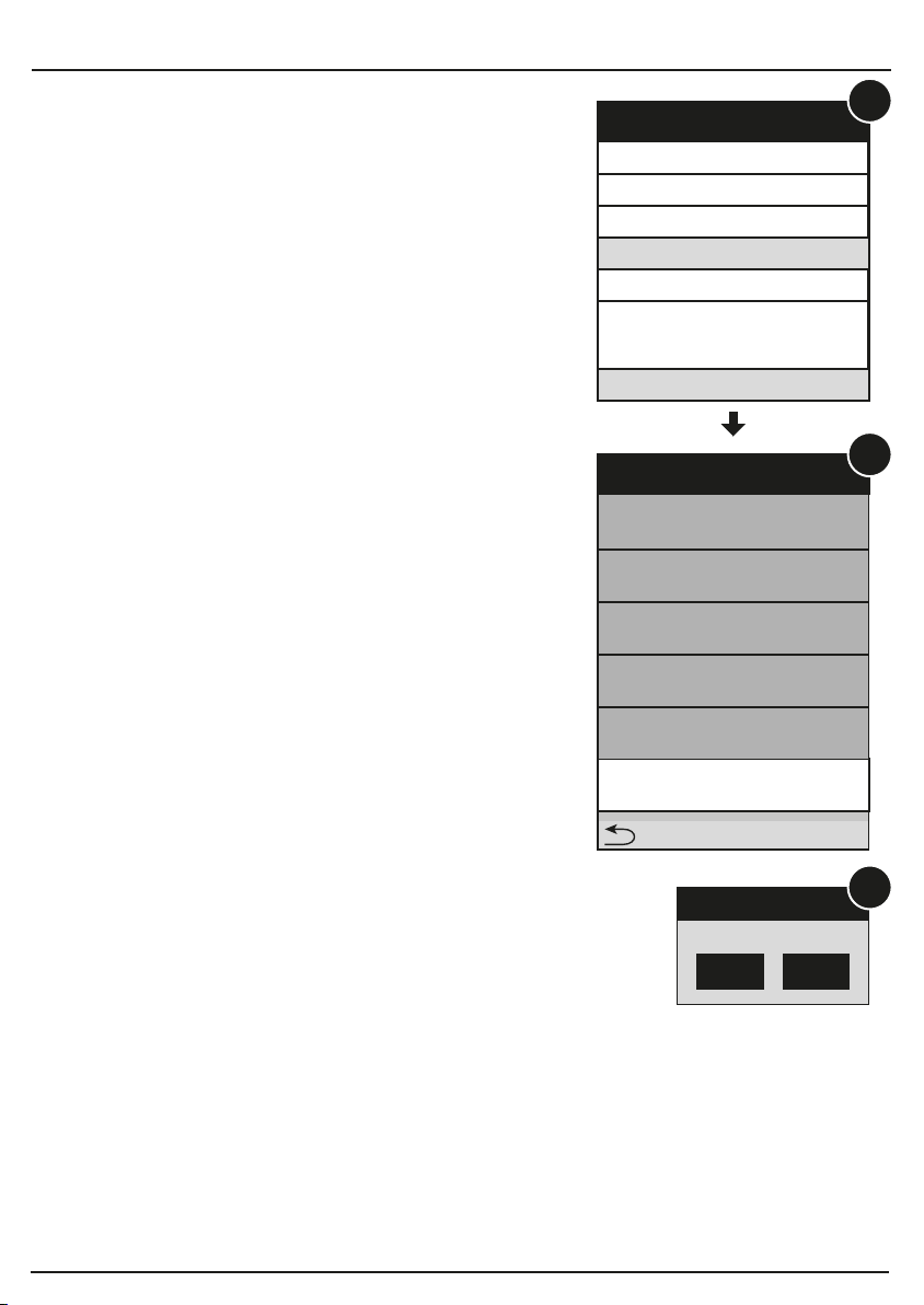
6. Highlight the "Tool Information" in Fig. 3 and press [OK].
7. The Register Code shown in Fig. 4 is the Register Code
needed in step 3.
(Return to step 3 and input the Register Code and then
proceed)
8. Install the TF card from the tool into the supplied USB TF
card adaptor and insert into the USB port of the
computer.
9. Reopen the update tool, select the updates you would
like to perform or click "Select All", and then click
[Download] to start downloading.
(Note: For CR9 l 0, only one piece of diagnostic software
can be selected and downloaded.)
10 Once all steps are complete, reinsert the TF card into the
tool and power the tool via USB cable or via OBD II
cable. A dialog box (Note: If only diagnostic software is
updated and no firmware package is downloaded, this
box will not appear) prompting you to update will pop up
on the screen (See Fig. 6), select [OK].
11. The registration process is complete, your tool is now
ready for use.
DLC Location Information
DTC Library
Abbreviation
Tool information
About OBD
Help
3/5
Tool Information
Boot version:
V02.01
Display program veson:
V02.00
Diagnostic program version:
V11.23
Diagnostic library version:
V11.28
Serial Number:
974990000001
Register Code:
4d001e001151
-Exit
Sure upgrade?
ESC OK
System upgrade
4
5
6
- 11 -

Select Language
Product Serial Number
Device Upgrade
English
9. REGISTER & UPDATE
9.3 METHOD 2: VIA USB CABLE
Note: Make sure the computer has an Internet connection.
1. Connect one end of the USB cable to the USB port of computer, and the other end to the tool.
2. If a newer version is found, a screen similar to Fig. 7 appears.
3. Press [OK] to configure this tool as a USB device. See Fig. 8. (Note: The Serial Number and
Register Code shown in this figure are needed for inputting in Steps 4-6.)
4. Launch the update tool, a screen similar to Fig. 9 will appear.
5. Type in the Serial Number. Click [Device Upgrade] to input the information and click [Submit] to
enter the update page.
Help
4
Boot Version: V10.02
Serial Number:
974990000001
Register Code:
4d001e001151
Check for new version?
Note: Internet connection is
required for PC.
Yes-OKAY No-ESC
Boot Version• V10.02
Serial Number:
974990000001
Register Code:
4d001e001151
Caution:
DO NOT disconnect USB
while downloading.
The unit should be re-powered
after downloading new version.
6. Select the updates you would like to perform or click "Select All", and then click [Download] to
start downloading. (Note: For CR910, only one piece of diagnostic software can be selected
and downloaded.)
7. Once all steps are complete, restart your tool. It will prompt you to upgrade, click [OK] to start
updating. It may take several minutes to finish the update.
8. The update process is complete, your tool is now ready for use.
7 8
9
- 12 -

10.1 FUNCTIONS
Once the tool is powered, it will enters the main menu screen, it mainly includes the following
functions:
• Diagnose: It mainly consists of OBD/EOBD diagnosing and Reset/System Scanning (varies
with product models).
• Review: To review the recorded DTC, datastream etc.
• Settings: To configure the system language, measurement units, turn on/off beeper and
recording mode.
• Help: Includes DLC location, DTC lookup and tool information etc.
10. MAIN MENU SCREEN
12.1 DIAGNOSIS FLOWCHART OF VEHICLE SYSTEM
12. START DIAGNOSTICS
The tool supports multiple languages. To change the language, select "Settings"-> "Language",
choose the desired one from the list and press [OK].
11. CHANGE LANGUAGE
Select "Diagnose"
Select "Scan"
(See Note*1)
Select Vehicle
Manufacturer
Select Vehicle Model
Select test system
Select test function
Clear fault code
Read fault code
Manual Select
(Note: In this case, you need to
choose the desired system
manually. Just follow the
onscreen instructions to proceed)
Automatic
(Note: This mode allows your tool
to scan the vehicle test system
automatically)
- 13 -

13. DISPOSAL
13.1 DISPOSAL
– At the end of the machine’s working life, or when it can no longer be repaired, ensure that it is
disposed of according to national regulations.
– Contact your local authority for details of collection schemes in your area.
In all circumstances:
•Do not dispose of power tools with domestic waste.
•Do not incinerate.
•Do not abandon in the environment.
• Do not dispose of WEEE* as unsorted municipal waste.
* Waste Electrical & Electronic Equipment.
- 14 -

NOTES
- 15 -

Draper Tools Limited, Hursley Road,
Chandler's Ford, Eastleigh, Hampshire. SO53 1YF. U.K.
Diagnostic Helpline: Tel. +44 (0) 330 0552100
Sales Desk: (023) 8049 4333
Internet: drapertools.com
General Enquiries: (023) 8026 6355
Service/Warranty Repair Agent:
For aftersales servicing or warranty repairs, please contact the
Draper Tools Helpline for details of an agent in your local area.
©Published by Draper Tools Limited.
No part of this publication may be reproduced, stored in a retrieval system or transmitted in any form or by any means,
electronic, mechanical photocopying, recording or otherwise without prior permission in writing from Draper Tools Ltd.
CONTACTS
YOUR DRAPER STOCKIST
DBMC0518
This manual suits for next models
1
Table of contents
Other Draper Diagnostic Equipment manuals


