Baxall DTL-960E User manual

Please read this manual before installing your equipment
DTL-960e User Manual
Single Channel Colour Digital Video Recorder

Page 2
DTL-960e Single Channel Colour Digital Video Recorder User Manual
IMPORTANT
The first few pages of these instructions contain important information on safety and product
conformity. Please read, and ensure that you understand this information before continuing.

Page 3
User Manual DTL-960e Single Colour Channel Digital Video Recorder
CONTENTS
Important Safeguards ............................................................................................................................................................................. 4
Product Safety ........................................................................................................................................................................................... 4
Damage Requiring Ser ice ..................................................................................................................................................................... 5
Electromagnetic Compatibility (EMC) .................................................................................................................................................. 5
Manufacturers Declaration of Conformance .................................................................................................................................... 5
Unpacking ................................................................................................................................................................................................... 5
Installation En ironment ......................................................................................................................................................................... 5
Features, Connections and Setup
Product Description and Features ............................................................................................................................................................... 7
Passwords ................................................................................................................................................................................................... 7
Front Panel Display ....................................................................................................................................................................................... 7
Front Panel Controls ..................................................................................................................................................................................... 8
Rear Panel Connections ............................................................................................................................................................................... 9
User Operations
Recording ................................................................................................................................................................................................... 14
Play ack ..................................................................................................................................................................................................... 15
The Search Interface ................................................................................................................................................................................. 16
The Menu System ....................................................................................................................................................................................... 17
The Operator Menu
Time/Date .................................................................................................................................................................................................... 19
Alarms ........................................................................................................................................................................................................ 20
Timer Settings ............................................................................................................................................................................................. 21
Record Settings .......................................................................................................................................................................................... 23
Display Settings .......................................................................................................................................................................................... 24
Archive Setup ............................................................................................................................................................................................. 25
Main Menu ................................................................................................................................................................................................... 27
The Main Menu
Disk Overwrite Mode .................................................................................................................................................................................. 29
Disk Maintenance ....................................................................................................................................................................................... 30
Audio Record Setting ................................................................................................................................................................................. 30
Auto Delete Mode ....................................................................................................................................................................................... 31
Communications (Including Ethernet Settings) .......................................................................................................................................... 31
Multiplexer Format ...................................................................................................................................................................................... 31
Adjust Picture ............................................................................................................................................................................................. 32
Front Panel Lock ......................................................................................................................................................................................... 32
Factory Settings ......................................................................................................................................................................................... 32
Change Password ..................................................................................................................................................................................... 33
RS-232 Remote Protocol ....................................................................................................................................................................... 34
Factory Defaults ...................................................................................................................................................................................... 36
Technical Specifications ....................................................................................................................................................................... 37
Appendix: Archi ing De ices ............................................................................................................................................................... 39

Page 4
DTL-960e Single Channel Colour Digital Video Recorder User Manual
IMPORTANT SAFEGUARDS
This product is exclusively for use in CCTV applications and has no other purpose.
Read and Retain these instructions - All the safety and operating instructions should be read before the unit is operated
and should be retained for future reference.
Cleaning - Unplug the unit from the supply outlet before cleaning. Use a damp cloth for cleaning. Do not use liquid or
aerosol cleaners.
Attachments - Do not use attachments that have not been recommended by the product manufacturer as they may
cause ha ards.
Water and Moisture - Do not use this unit near water. For example, near a bathtub, wash bowl, kitchen sink, or laundry
tub, in a wet basement, near a swimming pool, in an unprotected outdoor installation, or any area that is classified as a
wet location.
Accessories - Do not place this unit on an unstable stand, tripod, bracket, or mount. The unit may fall, causing serious
injury to a person and serious damage to the unit. Any mounting of the unit should follow the manufacturers instructions,
and should use a mounting accessory recommended by the manufacturer.
Ventilation - Openings in the enclosure are provided for ventilation to ensure reliable operation of the unit and to protect
it from overheating. These openings must not be blocked or covered, and therefore this unit should not be placed in a
built-in installation unless proper ventilation is provided. Do not place directly on other hot equipment, because this may
increase its operating temperature.
ower Sources - This unit should be operated only from the class 2 isolated power supply provided.
ower-cord rotection - Power-supply cords should be routed so that they are not likely to be walked on or pinched by
items placed upon or against them, paying particular attention to cords at plugs, and the point where they exit from the
appliance.
Overloading - Do not overload outlets and extension cords as this can result in a risk of fire or electric shock.
Object and Liquid Entry - This equipment must be protected from the ingress of foreign materials. Never push objects of
any kind into this unit through openings as they may touch dangerous voltage points or short-out parts that could result
in a fire or electric shock. Never spill liquid of any kind on the unit.
Servicing - There are no user-serviceable parts. Do not remove the covers as this may expose you to dangerous voltages
or other ha ards. Refer all servicing to qualified service personnel.
Replacement arts - When replacement parts are required, be sure the service technician has used the replacement
parts specified by the manufacturer. The use of unauthorised substitute components may result in fire, electric shock or
other ha ards.
Safety Check - Upon completion of any service or repairs to this unit, ask the service technician to perform safety checks
to determine that the unit is in proper operating condition.
Coax Grounding - If an outside cable system is connected to the unit, be sure the cable system is grounded.
Lightning - For added protection of this unit during a lightning storm, or when it is left unattended and unused for long
periods, unplug it from the wall outlet and disconnect the cable system. This will prevent damage to the unit due to
lightning and power-line surges.
PRODUCT SAFETY
Installation is only to be carried out by competent, qualified and experienced personnel in accordance with the
country of installations National Wiring Regulations.
Your Digital Recorder contains no user-serviceable parts.
This unit contains a lithium battery whose expected life is in excess of five years. If your Digital Recorder loses its
settings each time it is switched off then the battery needs replacing. In this instance return your Digital Recorder
to Baxall Limited and we will replace the battery.
There is a danger of explosion if the lithium battery is incorrectly replaced. Replace only with the same or an
equivalent type recommended by the manufacturer. Dispose of unused batteries according to the manufacturers
instructions.
Your Digital Recorder must not be used in a medical and/or intrinsically safe application.
Do not exceed the voltage and temperature limits given in the specification. Only operate your Digital Recorder in
a clean, dry, dust-free environment.

Page 5
User Manual DTL-960e Single Colour Channel Digital Video Recorder
DAMAGE REQUIRING SERVICE
Unplug the unit from the outlet and refer servicing to qualified service personnel under the following conditions:
When the power-supply cord or plug is damaged.
If liquid has been spilled, or objects have fallen into the unit.
If the unit has been exposed to rain or water.
If the unit does not operate normally by following the operating instructions.
If the unit has been dropped or the cabinet has been damaged.
When the unit exhibits a distinct change in performance.
If the unit has no power even when the power supply appears to operate correctly. If this is the case then ask a
service engineer to test the internal fuse.
ELECTROMAGNETIC COMPATIBILITY (EMC)
This is a Class A product. In a domestic environment this product may cause radio interference, in which case, the user
may be required to take adequate measures.
MANUFACTURERS DECLARATION OF CONFORMANCE
A Declaration of Conformity in accordance with the above EU standards has been made and is on file at Baxall Limited,
Stockport, SK6 2SU, England.
The manufacturer declares that the product supplied with this document is compliant with the provisions of the EMC
Directive 89/336 EEC, the Low Voltage Directive LVD 73/23 EEC, the CE Marking Directive 93/68 EEC and all associated
amendments.
The product is also Y2K compliant in accordance with British Standards Institution, DISC PD2000-1.
UNPACKING
Check the package and contents for visible damage. The packaging should contain:
The Baxall DTL-960e unit.
Accessories PCB.
A 12-volt power supply with power cable.
The DTL-960e user manual.
WaveReader software with instruction manual.
If any components are missing or damaged, contact the supplier immediately. Do not attempt to use the unit. If, for any
reason they must be returned, the contents must be shipped in the original packaging.
INSTALLATION ENVIRONMENT
ower:
Ensure that the sites AC power is stable and within the rated voltage of the external power supply. If the sites AC power
is likely to have spikes or power dips, use power line conditioning or an Uninterruptable Power Supply (UPS).
Ventilation:
Install the unit in a well-ventilated area. Take note of the locations of the cooling vents in the units enclosure, and ensure
that they are not obstructed.
Temperature:
Observe the units ambient temperature specifications when choosing a location space. Extremes of heat or cold beyond
the specified operating temperature limits may cause the unit to fail. Do not install the unit on top of other hot equipment.
Moisture:
Do not expose the unit to rain or moisture. Moisture can damage the internal components. Do not install this unit near
sources of water.
Chassis:
You can place other equipment on top of the unit if it weighs less than 35 pounds.

Page 6
DTL-960e Single Channel Colour Digital Video Recorder User Manual
FEATURES CONNECTIONS
AND SETUP

Page 7
User Manual DTL-960e Single Colour Channel Digital Video Recorder
PRODUCT DESCRIPTION AND FEATURES
The DTL-960e is a Digital Video Recorder designed to be a direct replacement for a Time Lapse VCR. Digital video
recording allows the user to have continuous recording on a hard disk, without the need for replacing or rewinding of
videotapes. The DTL-960e provides menu based search capabilities for recorded events, as well as access to live or
recorded data via the Ethernet.
Features of the DTL-960e include:
Single channel VHS or SVHS Input/Output connection.
Accepts single camera input or a multiplexed input from most popular multiplexers.
Compatible with color or monochrome cameras.
Records up to 50 pictures per second (PAL).
Continuous recording in Disk Overwrite mode.
LCD on front panel indicates Time, Date, Mode, and Record Speed in pps.
Video archiving via the units SCSI port.
Access to live or recorded video via the Ethernet.
Continues recording while archiving or transmitting via the Ethernet.
A simple on-screen menu system.
Includes WaveReader software for viewing live or recorded images on a PC.
Facility to program time-recorded events.
PASSWORDS
A password is provided to limit access to the Main menu. It is recommended that the default password be changed after
installation is complete. As a security measure, store the password in the administrators secured files or in a limited
access area. For instructions on entering the Main menu with the password, see page 27.
A password is also provided to return the unit to the factory defaults. For instructions on returning the unit to the factory
defaults, see page 32.
FRONT PANEL DISPLAY
Time - Displays the current time in Record and Stop mode. Displays the time the event was recorded in Play and
Pause modes.
Date - Displays the current date in Record and Stop mode. Displays the date the event was recorded in Play and
Pause modes.
Mode - Displays the mode (Record, Play, Pause, Stop, Etc.) the unit is in.
Record Speed - Displays the normal record or playback speed in pps.
assword Name Function Changeable by user? assword
Main Menu Password Provides access to the Main Yes: See page 33. 3 4 7
menu for the installer.
Factory Password Restores the unit to the No 8 1 1
factory defaults.
Page 8
DTL-960e Single Channel Colour Digital Video Recorder User Manual
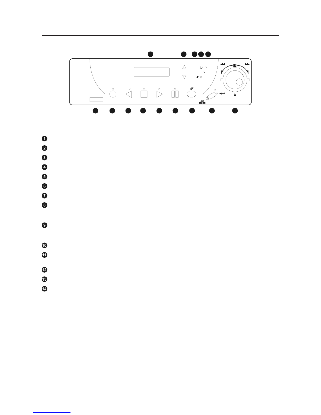
FRONT PANEL CONTROLS
RECORD REVERSE PLAY STOP PLAY PAUSE
REC/PLAY
SPEED
SEARCH
ALARM
POWER
LOSS
POWER
MENU
ENTER
REW
FF
10 11 12 13 14
1 2 3 4 5 6 7
8
9
Figure 2 - Front Panel Controls
Infrared ort - This feature is not yet available.
Record button - Press this button to begin recording.
Reverse play button - Press this button to playback video in reverse at the normal record speed.
Stop button - Press this button to stop recording or playback.
lay Forward button - Press this button to playback video at the normal record speed.
ause button - Press this button to pause playback.
Search button - Press this button to enter the Search Filters menu.
Combination Menu and Enter button - Press the lower half of the button (the Menu button) to enter the menu
system. This half of the button is also used to exit without saving while in the menu system. Press the upper half of
the button (the Enter button) to make or confirm a selection in the menu system.
Jog / Shuttle - The Jog (the inner of the two dials) is used for single frame advance while in Pause mode, and is also
used to change the value of a parameter while in the menu system. The Shuttle (the outer of the two dials) is used
to fast forward and rewind while in the Play mode, and is also used to navigate while in the menu system.
LCD - Displays the time, date, mode, and record or playback speed in pictures per second (pps).
Increase and Decrease Record Speed buttons - Press these buttons to increase or decrease the record or
playback speed.
Alarm Indicator - Indicates an alarm condition when the LED is lit.
ower Loss Indicator - Indicates power loss when LED is lit.
ower On Indicator - Indicates power is on when LED is lit.

Page 9
User Manual DTL-960e Single Colour Channel Digital Video Recorder
REAR PANEL CONNECTIONS
Ethernet ort
The Ethernet Port is used to view live or recorded images on a PC via the Ethernet.
The cable connection configuration depends on your network configuration:
For a DTL-960e that connects directly to a Hub, use a Straight Through connection.
For a DTL-960e that connects directly to a PC, use a Cross Over connection.
Consult with your Network Administrator for the specific type of configuration. See page 31 for information about configuring
the ethernet settings in the menu system.
ower Connector
The unit is furnished with a 12V DC power supply.
Do not use any other power supply with the unit. The manufacturer accepts no responsibility for damage caused by the
use of any other power supply.
Wire Type Cat 5
Connector Type RJ-45
Max Cable Length 100 feet / 30.5 meters
Minimum Cable Length 6 feet / 1.8 meters
Hub Wiring Configuration Straight Through
C Wiring Configuration Cross Over
ower Supply Input:
Voltage 120 to 240 Volt AC
Tolerance ±10%
Frequency 50 to 60 H
ower Supply Output:
Voltage 12 Volt DC
ower 62 Watts
Connector 2.1mm barrel, Centre Positive
Figure 4 - RJ-45 in Configuration
For Ethernet ort
12345678
Pin Use
1 TX+
2 TX-
3 RX+
4 Not connected
5 Not connected
6 RX-
7 Not connected
8 Not connected

Page 10
DTL-960e Single Channel Colour Digital Video Recorder User Manual
REAR PANEL CONNECTIONS
SCSI ort
The unit is equipped with a SCSI port for connecting external archive devices. The unit only supports a single SCSI device.
The SCSI ID must be set to 0 and the SCSI bus must be terminated, otherwise the system will not operate correctly.
Audio In/Out
The unit is equipped with a mono audio input and output for the recording and playback of sound.
, Video Input and Output
The unit is equipped with both SVHS (Y/C separated video signal) and Composite inputs and outputs. The video inputs
are auto-terminating.
The SVHS input is Active Looping, and will only loop while the unit is on.
Do not connect both video inputs at the same time.
RS-232 Serial ort
The RS-232 Serial Port is provided for software upgrades, and for external control of the unit. Use a Null Modem cable
when connecting to a PC.
When connecting to a multiplexer, it may be necessary to construct a cable using the pin-out documentation of the MUX
as a guide. See the pin-out configuration for the DTL-960e below.
Connector 50 Pin, High Density SCSI-2
Gender (on unit) Female
Compatible devices DAT, AIT, CD-R, CD-RW
Autoloader Support? Yes
SCSI ID 0
Connector Type DB9
Gender (on unit) Male
Cable Required (Connected to C) Null Modem
Cable Required (Connected to Multiplexer) Variable, depending on pin-out configuration of MUX
Pin Use
1 DCD
2RX
3TX
4 Not connected
5 Ground
6 Not connected
7 RTS
8 CTS
9 Not connected
Figure 5 - DB-9 in Configuration
For RS-232 Serial ort
1
5
69
SVHS Input 4-pin Mini-DIN connector
SVHS Output 4-pin Mini-DIN connector
SVHS Looping Only while unit is On
Composite Input 75 Ohm BNC connector
Composite Output 75 Ohm BNC connector
Composite Looping Yes, while unit is On or Off

Page 11
User Manual DTL-960e Single Colour Channel Digital Video Recorder
REAR PANEL CONNECTIONS
Accessories I/O ort
The rear panel of the unit is equipped with an Accessories Port (DB-9 style connector). It is used for connecting peripheral
devices such as alarm devices, alarm relays, or the VEXT connection.
Wire all accessories to the Accessories PCB (supplied with the unit), and connect it to the Accessories Port.
Do not attempt to wire accessories directly to the DB-9 connector.
Alarm In
An alarm condition can be activated by an Active Low TTL input or by relay contact devices such as pressure pads, passive
infrareds, door switches, or other similar devices.
min. duration: 0.5 sec.
I
nput
H
igh
L
ow
: Active Low TTL with pull-ups or Normally Open relay
: 5V (12V max.)
: Ground
ACCESSORIES PCB
TYPICALALARM DEVICE
Pin 1
Pin 7 or 10
Alarm Input
Ground
Volt-free
Normally open
(closes upon alarm)
Figure 7 - A Normally Open Relay Alarm Condition
Alarm Out
The Alarm output is activated when a teletext alarm is read, or while the Alarm Input is active. The Alarm output is only
active for the duration of the alarm event.
Low for duration of alarm
I
nput
H
igh
L
ow
Current out
: Active Low
: 12V
: Ground
: 50mAmax. (short circuit protected)
Figure 6 - in Configuration for Accessories CB
1
2
3
4
5
6
7
8
9
GND
Pin Use
1 Alar In
2 Alar Out
3 Record Start In
4 Alar Record Reset
5 VEXT Pulse Out
6 Error Out
7 Ground
8 Videoloss Out
9 Disk End Out
10 Ground

Page 12
DTL-960e Single Channel Colour Digital Video Recorder User Manual
REAR PANEL CONNECTIONS
Record Start In
Record Start In will place the unit in Record mode when activated. Compatible with the Disk End Out signal from a second
unit.
min. duration: 0.5 sec.
I
nput
H
igh
L
ow
: Active Low TTL with pull-ups or Normally Open relay
: 5V (12V max.)
: Ground
Alarm Record Reset
This feature is for future development, and has not yet been implemented.
VEXT ulse Out
The Video External Pulse connection (VEXT) simplifies multiplexer operation by automatically synchroni ing the multiplexer
and the DTL-960e. The DTL-960e sends a VEXT pulse to the multiplexer indicating that it is ready to record the next
image. The multiplexer responds by sending the next image to the Video Input on the DTL-960e.
The VEXT connection is especially beneficial for units configured with dual record speeds (Normal and Alarm).
Output
H
igh
L
ow
Current out
: Active Low
: 5V
: Ground (0.8V max.)
: 50mAmax. (short circuit protected)
Use of the VEXT connection is highly recommended when connecting the unit to a multiplexer.
Error Out
This feature is for future development, and has not yet been implemented.
Videoloss Out
The Videoloss Out signal is activated when the unit experiences videoloss on the selected video input (Composite or
SVHS).
In the event of videoloss, VIDEOLOSS will be indicated near the upper left hand corner of the primary monitor.
min. duration: 0.5 sec.
O
utput
H
igh
L
ow
A
ctive when On
Current out
: Open Collector
: Transistor Off
: Transistor On
: 10mA max.
Disk End Out
The Disk End Out is activated when there is 5 minutes of recording space left on the hard disk.
min. duration: 0.5 sec.
O
utput
H
igh
L
ow
A
ctive when On
Current out
: Open Collector
: Transistor Off
: Transistor On
: 10mA max.

Page 13
User Manual DTL-960e Single Colour Channel Digital Video Recorder
USER OPERATIONS

Page 14
DTL-960e Single Channel Colour Digital Video Recorder User Manual
RECORDING
To begin recording, press the Record button. RECORD will be indicated for three seconds, near the
upper left hand corner of the primary monitor. The unit always starts recording at the end of the
previously recorded data.
Recording will continue until:
Another mode is selected (Play mode, Stop mode, Fast Forward, Etc.).
The disk is full (in No Overwrite and Overwrite Once modes). See page 29 for details regarding
Disk Overwrite modes.
Videoloss is detected. In the event of videoloss, VIDEOLOSS will be indicated near the upper left
hand corner of the primary monitor.
Normal Record Speed
The unit records at the normal record speed until an alarm condition is detected. The normal record
speed is indicated on the LCD, and can be altered using the Up/Down Record Speed buttons, or in
the menu system. The normal record speed can be altered while the unit is recording.
For information about altering the normal record speed using the menu system, see page 23.
Alarm Record Speed
When an alarm condition is detected, the unit automatically switches to the alarm record speed. The alarm condition is
indicated in several ways:
With the word ALARM, displayed on the primary monitor, near the upper left hand corner of the screen.
With the LED Alarm Indicator on the front panel of the unit.
With the internal bu er (if activated in the menu system). For information about activating the internal bu er during
alarms, see page 20.
By an external device, connected to the alarm output of the unit (if the unit is installed that way).
The alarm record speed cannot be changed using the Up/Down Record Speed buttons on the front panel. This must be
carried out using the menu system. For information about altering the alarm record speed and incident recording in
general, see page 23.
During an alarm condition, the front panel LCD does not change and continues to display the normal record speed,
although the unit is recording at alarm record speed. The unit returns to the normal record speed when the alarm
condition ends.
Note: If a teletext alarm is received from the multiplexer, the DTL-960e must be in Record mode in order to automatically
switch to alarm record speed. See page 20 for more information on the teletext alarm.
Disk Full Notification
When the disk is full, a message will appear on the primary monitor to indicate that the unit has stopped recording,
because there is no space to do so.
In No Overwrite mode: The user must acknowledge the on-screen message by pressing the Enter button. The unit will
not record over previously recorded data. To continue recording, the data must be erased (or deleted) using the Disk
Maintenance feature. For more details on this feature, see page 30.
In Overwrite Once mode: The user must acknowledge the on-screen message by pressing the Enter button. The unit
will continue recording again when the user presses the Record button.
RECORD
R
eco
rd
Button
REC/PLAY
SPEED
R
ecord Spee
d
Buttons
Figure 8 - LCD Display in Record mode
A. Current ti e
B. Current date
C. Record ode indicated
D. Nor al record speed in pictures per second
10:55:45A REC
19/05/01 0.2p
A
B
C
D

Page 15
User Manual DTL-960e Single Colour Channel Digital Video Recorder
PLAYBACK
When data is played back on the DTL-960e, the details on the front panel LCD change accordingly:
lay Forward
To begin normal playback, press the lay Forward button. The unit will begin playing back data from the
beginning of the last recording session. Playback is indicated:
As LAY near the upper left hand corner of the primary monitor, for three seconds.
As LAY> on the LCD.
Reverse lay
To begin reverse playback, press the Reverse play button. The unit will begin playing back data from the
beginning of the last recording session. Reverse playback is indicated:
As REVERSE LAY near the upper left hand corner of the primary monitor, for three seconds.
As LAY< on the LCD.
If there is only one recording session on the hard disk, the unit will indicate START OF DATA on the
primary monitor.
layback Speed
When playback commences, the unit will play the data at the rate it was recorded. However, the user can
alter the playback speed using the Up/Down Record Speed buttons.
Altering the playback speed overrides any change in playback speed that would occur due to an alarm
condition in the playback. To clear the override, press the Stop button, then press the lay button to
resume playback at the speed the data was recorded.
The playback speed is indicated on the LCD in Pictures Per Second.
Fast Forward & Rewind
During playback the data can be viewed at a higher than normal rate by rotating the Shuttle clockwise.
The data can also be viewed at a higher than normal rate in reverse by rotating the Shuttle counter-
clockwise. Increasing the amount of rotation increases the rate of playback. Fast Forward & Rewind are
indicated:
As FAST FORWARD or REWIND near the upper left hand corner of the primary monitor, for three
seconds.
As FFWD or REW on the LCD.
ause
During playback, press the ause button to pause playback, and display a single frame on-screen.
Pause is indicated:
As AUSE near the upper left hand corner of the primary monitor, for three seconds.
As AUSE on the LCD.
Single Frame Advance & Single Frame Rewind
During Pause mode, rotate the Jog dial to view the frame directly before or after the frame displayed on-screen.
Start of Data & End of Data
If the start or end of data is reached during playback, START OF DATA or END OF DATA is indicated near the upper left hand
corner of the primary monitor.
Figure 9 - LCD Display in layback mode
A. Ti e the data was recorded
B. Date the data was recorded
C. Play Forward ode indicated
D. Nor al record speed in pictures per second
12:34:45A PLAY>
17/12/01 0.2p
A
B
C
D
REW FF
Jog/Shuttle
PAUSE
P
aus
e
Button
PLAY
P
lay Forwa
rd
Button
REC/PLAY
SPEED
R
ecord Spee
d
Buttons
REVERSE PLAY
R
everse Pla
y
Button

Page 16
DTL-960e Single Channel Colour Digital Video Recorder User Manual
THE SEARCH INTERFACE
The Search Interface feature allows the user to search the hard disk for recorded events, such as an alarm
condition, or a previous recording session. For example, each time Record mode is activated, it is considered
a separate recording session.
To enter the Search Filters menu, press the Search button. The Search Filters menu is displayed on the
primary monitor:
Search Filters
Start Stop
DATE: 12/25/00 [ ] 01/01/01 [ ]
(MM/DD/YY) (MM/DD/YY)
[CANCEL] [START SEARCH]
Start Stop
TIME: 11:11:21 [ ] 12:34:34 [ ]
1 2 3 4 5 6 7 8
CAMERA: [ ] [ ] [ ] [ ] [ ] [ ] [ ] [ ]
ALARM: [ ]
Note: The Search Filters menu can also be accessed via the Selective Archive and Restore from Archive features in the
menu system. See page 25 for more details on these features.
Selecting a Start and Stop Date / Start and Stop Time:
1. Using the Shuttle to navigate, highlight the DATE parameter, then press the Enter button. The unit will enter Edit mode.
2. Use the Jog to change the start and stop date values. Use the Shuttle to navigate among the different parameters.
3. To activate the start or stop date parameter, use the Jog to place an [X] in the check box.
4. Press the Enter button at any time to exit Edit mode.
5. To select a Start and Stop Time, repeat steps 1 to 4 with the TIME parameter.
Selecting Cameras and Recorded Alarms:
1. Using the Shuttle to navigate, highlight the CAMERA parameter, then press the Enter button. The unit will enter Edit
mode.
2. Use the Shuttle to navigate among the different cameras.
3. Use the Jog to select a camera (or cameras) that is to be searched for alarms by placing an [X] in the check box.
4. Press the Enter button to exit Edit mode.
5. Using the Shuttle to navigate, highlight the ALARM parameter, then press the Enter button. The unit re-enters Edit
mode.
6. Use the Jog to activate the alarms search, by placing an [X] in the check box.
7. Press the Enter button at any time to exit Edit mode.
Note: It is possible to search for all recorded events. To do this, ensure that all the check boxes are blank [ ].
Starting the Search:
Using the Shuttle to navigate, highlight [START SEARCH] and then press the Enter button. The search results will appear.
To select a recorded event from the search results, use the Shuttle to highlight the event and then press the Enter button.
Press the Menu button to exit the Search Results menu.
SEARCH
S
earc
h
Button

Page 17
User Manual DTL-960e Single Colour Channel Digital Video Recorder
THE MENU SYSTEM
The DTL-960e can be configured using a menu based system that can be viewed when the unit is connected to a monitor.
The menu system contains two pull-down menus and a number of pop-up menus, and is accessed by pressing the
Menu button:
MENU
ENTE
R
ull-down menus
The pull-down menus are the top-level menus. By making a selection in a pull-down menu, the appropriate sub-menu
will open (typically a pop-up menu). Changes to the units parameters are usually made in the pop-up menus, not the
pull-down menus.
There are two pull-down menus available:
The Operator menu
The Operator menu provides access to all of the operator programmable options.
It also provides the entry point to the second pull-down menu, via the Main Menu option.
For details on this menu, see the section The Operator Menu that begins on the next page.
The Main menu
For security reasons, a password is provided to limit access to the Main menu. This password
must be entered when the Main Menu option is selected from the Operator menu.
The Main menu provides access to all of the installer programmable options.
For details on this menu, see the section The Main Menu that begins on page 28.
op-up menus
Pop-up menus usually have a parameter (or several parameters) from which the user can make a selection or change
the value of the parameter.
There are two types of pop-up menus:
The first type of pop-up menu has [OK] or [CANCEL] options at the bottom.
Use the Shuttle to select the parameter that you want to change, and then use the Jog to
change the value. To save the changes and exit the menu, use the Jog to select [OK], then
press the Enter button. To exit the menu without making changes, use the Jog to select
[CANCEL], then press the Enter button.
The Menu button can also be used to exit the pop-up menu at any time.
The second type of pop-up menu is different in that there are no [OK] or [CANCEL] options at
the bottom.
Use the Jog to change the value of the parameter. Press the Enter button to confirm the
selection and exit the menu, or press the Menu button to exit the menu without making
changes.
Time/Date
Alarms
Timer Settings
Record Settings
Display Settings
Archive Setup
Main Menu
Disk Overwrite Mode
Disk Maintenance
Audio Record Setting
Auto Delete Mode
Communications
Multiplexer Format
Adjust Picture
Front Panel Lock
Factory Settings
Change Password
[CANCEL] [OK]
Adjust Brightness
050
Select Mode
Continuous Overwrite
Archive Overwrite Mode

Page 18
DTL-960e Single Channel Colour Digital Video Recorder User Manual
THE OPERATOR MENU
This section covers the Operator menu system
Time/Date
Alarms
Timer Settings
Record Settings
Display Settings
Archive Setup
Main Menu

Page 19
User Manual DTL-960e Single Colour Channel Digital Video Recorder
Select Format
12 HOUR
Time Format Setup
Select Format
DD/MM/YY
Date Format Setup
HH MM SS
10 13 01
[CANCEL] [OK]
Time Setup
MM DD YY Day
01 01 98 1
[CANCEL] [OK]
Date Setup
Set Time Format
Set Date Format
Set Time
Set Date
TIME/DATE
When the Time/Date menu item is selected, a sub-menu is displayed. From this sub-menu,
you can specify:
The time format: 12 or 24 hours.
The date format: MM/DD/YY, DD/MM/YY, or YY/MM/DD.
The time.
The date.
Set Time Format
This menu option displays the Time Format Setup dialog. In this dialog, use the Jog to
select the desired time format. The options available are:
12 HOUR
24 HOUR
Press the Enter button to confirm the selection and exit the menu.
Set Date Format
This menu option displays the Date Format Setup dialog. In this dialog, use the Jog to
select the desired date format. The options available are:
DD/MM/YY
MM/DD/YY
YY/MM/DD
Press the Enter button to confirm the selection and exit the menu, or press the Menu button
to exit the menu without making changes.
Time Setup
This menu option displays the Time Setup dialog, where you can set the time. To do this:
1. With HH MM SS highlighted, press the Enter button. The highlighting will move to the
row of numbers.
2. Enter the time in Hours, Minutes, and Seconds. Use the Jog to change the values.
Use the Shuttle to navigate among the three fields.
3. Press the Enter button to confirm the selection.
4. To save the changes and exit the menu, use the Jog to select [OK], then press the
Enter button. If you want to exit the menu without making changes, use the Jog to
select [CANCEL], then press the Enter button.
Date Setup
This menu option displays the Date Setup dialog, where you can set the date. To do this:
1. With MM DD YY DAY highlighted, press the Enter button. The highlighting will move to
the row of numbers.
2. Enter the date in Months, Days, Years. The day of the week will update automatically. Use
the Jog to change the values. Use the Shuttle to navigate among the three fields.
3. Press the Enter button to confirm the selection.
4. To save the changes and exit the menu, use the Jog to select [OK], then press the
Enter button. If you want to exit the menu without making changes, use the Jog to
select [CANCEL], then press the Enter button.

Page 20
DTL-960e Single Channel Colour Digital Video Recorder User Manual
ALARMS
The Alarms menu is used to specify:
Whether an alarm condition will be activated when the unit detects a signal on
the Alarm In connection.
Whether a teletext alarm signal (generated by a multiplexer or other device) will
cause the unit to activate an alarm condition.
Whether the internal bu er is activated during an alarm condition.
To configure these alarm settings:
1. Use the Shuttle to navigate among the fields.
2. Use the Jog to change the values of the highlighted fields.
3. To save the changes and exit the menu, use the Jog to select [OK], then press
the Enter button. To exit the menu without making changes, use the Jog to select
[CANCEL], then press the Enter button.
Connecting to Dedicated Micros (DM)
A feature unique to the DTL-960e is its ability to detect alarms via teletext provided within the video signal. Standard Time
Lapse VCRs can only detect an alarm if the alarm output signal of the multiplexer is wired directly to the alarm input of the
VCR.
This alarm detecting feature of the DTL-960e is compatible with the following styles of multiplexers:
ZMX
Philips
Robot
To use this function on a Dedicated Micros multiplexers, you need to:
1. Connect the alarm output of the multiplexer to the alarm input of the DTL-960e (as you would do when connecting the
alarm input on standard time-lapse VCR).
2. In the Alarms menu, set the Hardwire Alarm option to Enable.
3. Set the Teletext Alarm option to Disable.
Hardwire Alarm : Enable
Teletext Alarm : Disable
Alarm Buzzer : Enable
[CANCEL] [OK]
Alarms Menu
Other manuals for DTL-960E
1
Table of contents
Other Baxall DVR manuals


