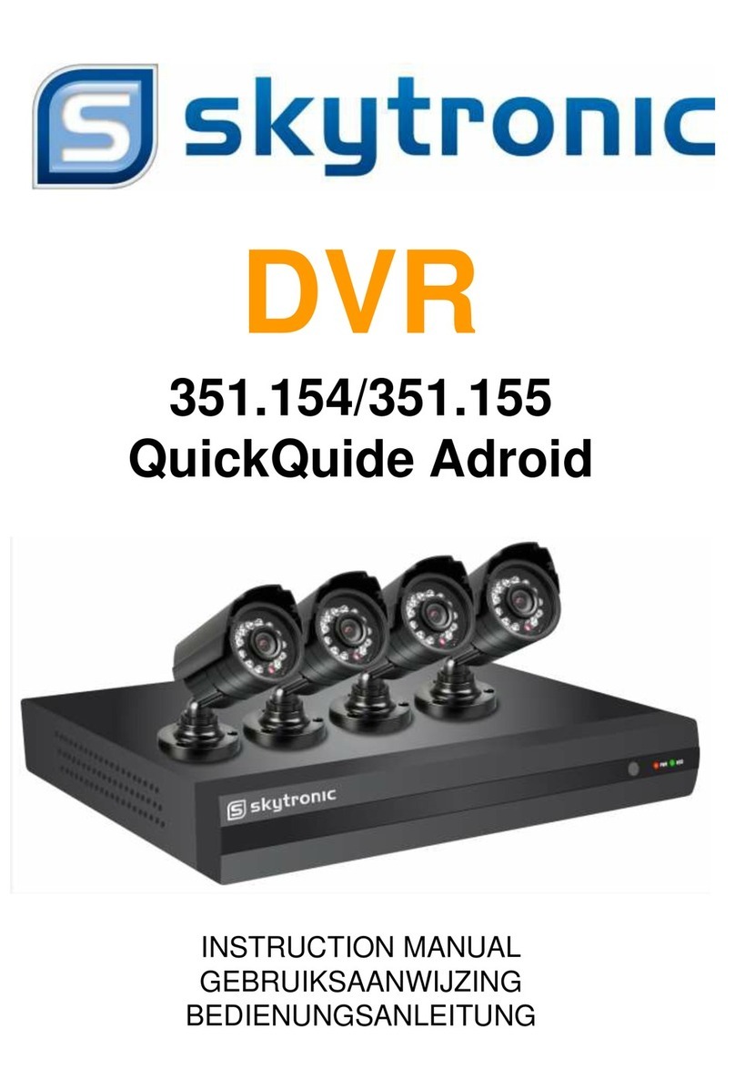
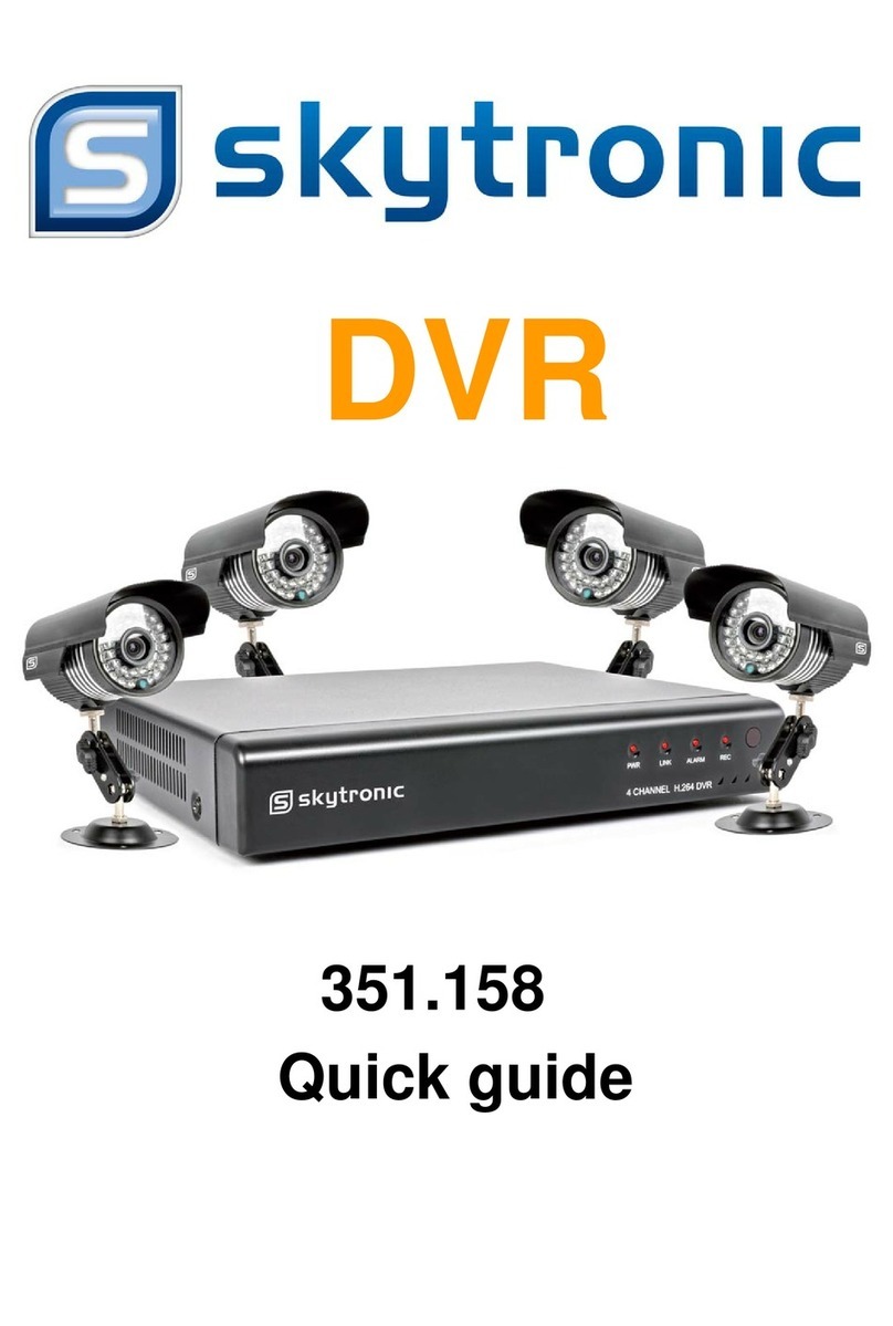
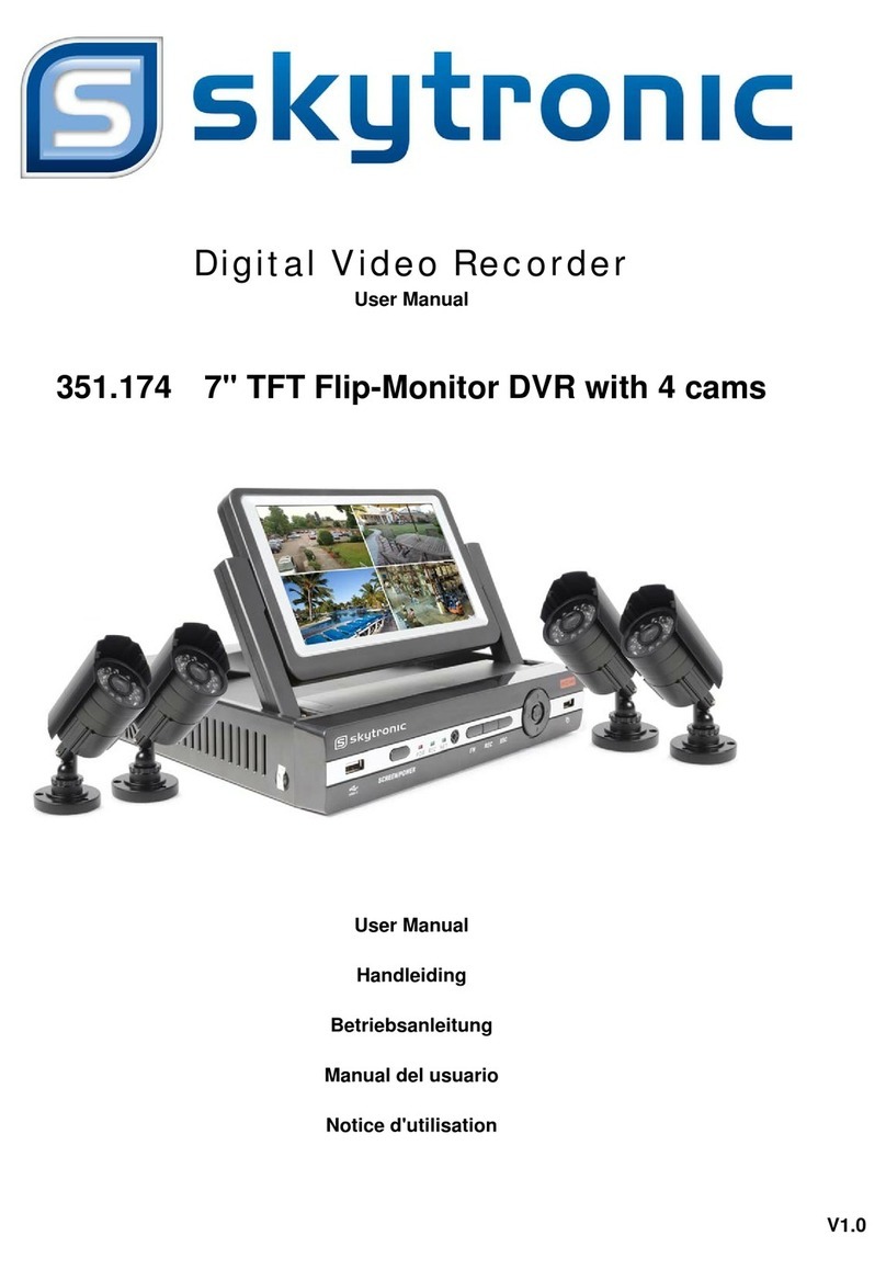
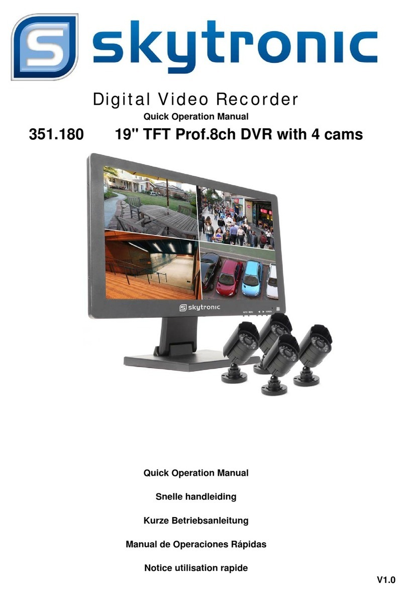
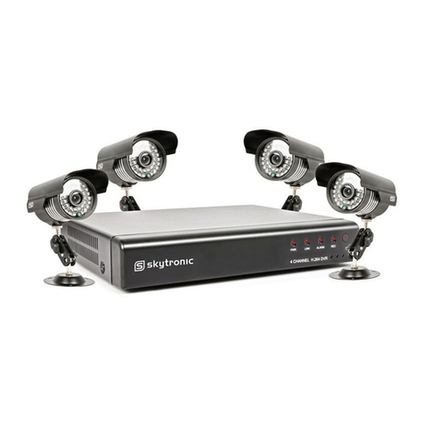
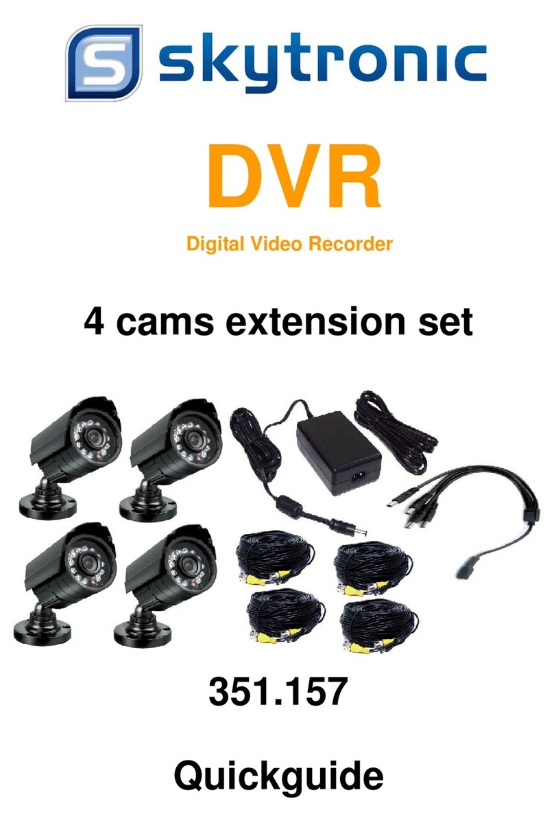
SKYTRONIC 351.142 User manual

351.142
19" Touchscreen TFT DVR with 4 cams
USER’S MANUAL
HANDLEIDING
GEBRAUCHSANLEITUNG
DVR
Digital Video Recorder

Touch Screen
1. This 19” LCD DVR support Touch Screen, mouse ,remote control various operation ways.
2. This 19”LCD DVR is touch screen model, please use your finger or other object to touch the
screen with a little pressure.
3. When the model is power on, please use your finger to touch any place 2-3 seconds, then it will
have menu, and use same operation ways to do any parameter setting.
4. Double touch make single channel to full screen, then double touch return back multiple pictures.
5. Whatever you connect 4pcs cameras or 8pcs cameras ,you can set the multiple screen in the
menu, main menu-multiple picture.
Attention:
Please don’t use sharp object to scratch the screen, don’t use huge pressure to touch
the screen or kick the screen.

Touch Screen
1. Deze 19” LCD DVR ondersteunt het gebruik van een Touch Screen, muis, en
afstandsbediening.
2. Gebruik uw vinger of een ander voorwerp om het LCD scherm van de monitor licht aan te
raken.
3. Om het menu op te halen drukt u 2 a 3 seconden licht met uw vinger op het scherm en doe dit
ook om de parameters in te stellen.
4. Als u twee keer achter elkaar op het scherm drukt verandert het scherm in volbeeld, als u nu
opnieuw twee keer achter elkaar op het scherm drukt komt het scherm terug met meerdere
beelden.
5. U kunt het aantal camera’s instellen in het menu (meerdere beelden) en de beelden hiervan
worden dan op het scherm weergegeven:
Ga naar main menu multiple picture.
Let op:
Gebruik geen scherpe voorwerpen of overmatige kracht bij het aanraken van het
scherm.

Touch Screen
1. Dieser 19 "LCD DVR unterstützt die Verwendung von einem Touch Screen, Maus und
Fernbedienung.
2. Benutzen Sie Ihren Finger oder einen Gegenstand um den LCD-Bildschirm des Monitors
leicht zu berühren.
3. Um in dem Menü zu gelangen drücken Sie 2 oder 3 Sekunden leicht mit Ihrem Finger auf dem
Bildschirm, und das Gleiche tun Sie um die Parameter einzugeben.
4. Wenn Sie zwei Mal in Folge auf dem Bildschirm drücken ändert sich der Bildschirm in
Vollbildmodus, wenn Sie wieder zweimal in Folge auf dem Bildschirm drücken kommt den
Bildschirm mit mehreren Bildern.
5. Sie können die Anzahl der Kameras im Menü (mehrere Bilder) eingeben und diese Bilder
werden dann auf dem Bildschirm angezeigt,
Gehen Sie zum Hauptmenü →multiple picture/mehreren Bildern.
Hinweis:
Verwenden Sie keine spitzen Gegenstände oder übermäßige Kraft beim
Berühren des Bildschirms.

Safety Instructions
1. Use proper power source.
Do not use this product with a power source that applies more than specified voltage (100-240V AC).
2. Never insert anything metallic into the DVR case.
Putting something into the DVR case can be a source of dangerous electric shock.
3. Do not operate in wet & dusty area or use near water.
Avoid places like a damp basement or dusty hallway.
4. Do not expose this product to rain or use near water.
If this product accidentally gets wet, unplug it and contact an authorized dealer immediately.
5. Keep product surfaces clean and dry.
To clean the outside case of the DVR, use a cloth lightly dampened with water (no solvents).
6. Provide proper ventilation.
This DVR has a built in fan that properly ventilates the system.
7. Do not attempt to remove the top cover.
If there are any unusual sounds or smells coming from the DVR, unplug it immediately and contact an
authorized dealer or service center.
8. Do not attempt to remove the top cover.
Warning: You may be subjected to severe electrical shock if you remove the cover of the DVR.
9. Handle DVR box carefully.
If you accidentally drop your DVR on any hard surface, it may cause a malfunction. If the DVR doesn’t work
properly due to physical damage, contact an authorized dealer for repair or exchange.
10. Use standard lithium cell battery. (NOTE: Manufacturer has preinstalled battery.)
The standard lithium cell 3v battery located on the mother board should be replaced if the time clock does not
hold its time after the power is turned off. Warning: unplug the DVR before replacing battery or you may be
subjected to severe electrical shock. Properly dispose of old batteries.
11. Make sure there is good air circulation around the unit.
This DVR system uses a hard drive for video storage, which generates heat during operation. Do not block air
holes (bottom, upper, sides and back) of the DVR that cool down the system while running. Install or place this
product in an area where there is good air circulation.
Chapter 1: DVR Features
Function Brief and Description
Real-time Monitoring
2 CH video output, support VGA virtual output, Net-viewer and Mobile
Live monitor, and also support zoom in/out, auto sequence and PIP
display.
Record Function
H.264 video compression format; record quality adjustable, multiple
record modes (Always, Scheduled, Manual, Alarm, Motion detection
and remote record)
Record storage Support SATA large capacity HDD and save real-time record image to
HDD.
Playback Support DVR single CH and multiple CH Search/Playback of recorded
files.
Backup Support DVR backup via USB flash drive, removable drive, Recorder
and network.
Alarm Setting Supports HDD & video input alarm management.
Network operation Supports remote surveillance by authority users to increase system
security.
Mouse Operation Supports Mouse operation for faster menu navigation.
PTZ Control Supports PTZ camera operations through RS-485.
List 1-1
Other Features:
H. 264 video compression format, supports D1, HD1, CIF resolution
ADPCM audio compression format
Windows Graphical interface
BNC and VGA video out ports
Supports remote live viewing via 3G mobile networks
Supports sending email alerts when motion is detected by system
Triplex (recording, playback and net transmitting at the same time)
Supports USB mouse, IR remote control operation
Rear USB2.0 ports for backup, upgrade and mouse operation.
Supports Double Encode bit network transmission
The video package time is adjustable
Multiple alarm record mode
Multiple language OSD
Supports auto maintenance

Chapter 2: Layoutt
Side Panel
Item Physical port Connection method
1 MENU Opens MENU-Screen
2 + Increase
3 - Decrease
4 USB USB Port

Rear Panel
Item Physical port Connection method
1 Video input Connect CH1-4 video input device(BNC interface)
2 Audio Output Connect signal output(RCA interface)
3 Audio input Connect CH1-4 audio signal input (RCA interface)
4 USB Port Connect USB device (Flash Drive, Hard Drive and Recorder etc)
5 RS-485/Sensor/Alarm RS485/Sensor/Alarm interface (see pin outs below)
6 Power Port Connect power supply - DC12V 3A
7 Video output Connect monitor output (BNC interface)
8 Ethernet: Port Connect LAN, Ethernet (RJ45 interface)
9 Power on/off
4CH

2.3 Remote Control
Mouse Operation
You can use a mouse instead of front panel buttons or remote control.
Click left key of
Mouse
In menu lock mode, Enter into pop-up menu and clicking any sub menu to pop up Log-in
window; on menu unlock mode, enter into pop-up menu, and then clicking left key to
enter into any sub menu directly.
After entering main menu, clicking left key could enter into any sub menu; On[Detailed
file] menu mode, clicking left key could playback one recording file.
Change the status of check box and motion detection area.
Clicking combo box to access pull-down menu
By clicking left key you can adjust Color control bar and volume control bar.
By clicking left key you can select values in edit boxes or pull-down menu and supports
Chinese word input, special symbol, numeric and character input, use instead of
[Enter- ] or [Backspace ]
In the [Detailed file] menu mode, clicking left key will playback one recording file.
Click right key of
Mouse
In live display mode, clicking right key will display pop-up menu (shown as Picture 5-1).
In Main menu or sub menu mode, clicking right key will exit current menu.
Double-click Left
key of Mouse In live display or playback mode, double-clicking left key will maximize the screen.
Moving Mouse Select menu item
Sliding Mouse On motion mode, sliding mouse will select motion area; On [Color set] menu mode,
sliding mouse will adjust color control bar and volume control bar.
List 2-3
1 1-8 Channel Select 1-8 ; Numeric key
2 9、0 Numeric Key
3 ALL Preview all Channel
4 Menu Enter/Exit Main Menu
5 ▲Up Key
6 ▼Down Key
7 ◄/Left / Right Key
8 SEL Select Key/ Edit Key
9 Rewind key
10 Play Key, Enter to recording search menu
11 Forward Key
12 ●Manual Recording
13 Pause / Frame Play
14 ■Stop manual recording; Stop Playback
15 Audio Undefined
16 Mute Undefined

Chapter 3: DVR Installation
3.1 Hard Drive Installation
Caution:Please do not Install or take out hard drive when DVR is running!
(1) Remove screws on two sides of the body and open DVR upper cover carefully;
(2) Some models has a HDD Drawer; Use provided key to take out . Insert Power Cord and data cable into Pin of
hard drive securely;
(3) Put the upper cover back carefully, re-attach screws.
3.2 Camera and Monitor Connection
Connect camera cable to video input of DVR, and from video output of DVR to Monitor via BNC connector
(Refer to section2.2-Rear Panel); or
If the camera is a PTZ speed dome, you could connect RS485 A & B to the according port of DVR respectively
(refer to system figuration on Chapter 8).
3.3 Power Supply connection
Please only use the power adapter supplied with the DVR .

Chapter 4: DVR Boot up
4.1 System Initialization
4.2 Main Interface
Note: When internal HDD is not connected or an error occurs, the character “H” will appear on the first channel
of the live screen and accompany buzzer alarm. If you want to close the buzzer alarm, please enter into [Device
manageAlarm setting] to set HDD loss and HDD space to “off”.
Chapter 5: DVR Menu
5.1 Pop-up Menu
Note: options of the Pop-up menu will differ depending on different parameter setting and application environment.
After connecting the power adapter and turning
On the power button, the system will boot-up and start
initializing.
After finishing system initialization the system will enter into main
interface. Picture 4-2 is the main interface displayed by system, which
is showing no video input status. Once there are video inputs, the
interface will display live images from the cameras. In main interface
mode, if you use the mouse to double-click the live image of any
channel, the image will be maximized to full screen, by double-clicking
again, the display will be come back to quad mode displaying all
cameras; clicking the right button of the mouse, will enter into Pop-up
Menu; by clicking the left button of the mouse, you select menu items;
when clicking any area outside the menu, you will exit the Pop-up
menu.
Picture 4-1
Picture 4-2
Picture 5-1
Picture 5-1cPicture 5-1
a
Picture 5-1b

5.2 Main Menu Guide
After finishing system initialization, click right key of mouse on main interface
mode to enter into Pop-up Menu. Now you could proceed parameter setting and
operate for Main Menu, Multi Pics, PTZ, PIP, REC Seatch, Mute, Manual REC,
Start Rotate
,
Start Cruise and GUI to VGA etc.
Record
Resolution
Scheduled
Main Menu
Camera Color Set
Title Set
Dis
p
la
y
set
Network
Static set
DHCP set
PPPoE set
DDNS set
Search File List
Search/Pla
y
back
Lo
g
Search
File Backu
p
Lo
g
Ex
p
ort
Device Mana
g
ePTZ set
Alarm set
3G Networ
k
HDD
Motion Area set
Email set
S
y
ste
m
Lan
g
ua
g
e
Information
Password
Maintain Back to Factor
y
Time
A/V
Volume
Mar
g
in

Picture 5-5
5.3 Main Menu
5.3.1 Display setup
The modifications will be available after clicking [APPLY] button on the bottom
of the sub-menu windows and being prompted to save and then clicking [ok]
button.
If you want to cancel the modification, click [Exit] button to exit the menu.
When clicking [DEFAULT] button, all system default values will be reset to
default value.
System default value indicates the value pre-set at the factory.
5.3.2 Record setup
Click [Main Menu] [Record] to enter into [Record Setup] menu (Shown as Picture 5-6).
[Record] option allows you set up record status (Enable/Disable) of each channel.
[Bit rate] include three options – Best, Good and Normal.
Pack Time : indicates max continuous rec. time (15, 30, 45 and 60minutes)
After clicking right button of mouse, pop-up menu will be displayed
on the screen. You can click [main menu] button on pop-up menu
to enter into Main menu interface (Shown as Picture 5-2). In Main
Menu mode, you can control device management settings, such as
Display, Recording, Network, Recording search, Device and
System settings etc.
Go to [Main Menu Camera] to set up the name display and
position display of each channel CH (Shown as Picture 5-3),
You can also adjust image brightness, saturation, contrast and
hue settings of each channel after entering into [Color] Menu
and set up whether each channel can be previewed or not
under Live display and/or Recording mode.
Please note that the name of each channel supports up to eight
characters.
Copy : This function allows you to copy all data of one channel
to any other channel.
The Color Menu, where you can adjust image brightness,
saturation, contrast and hue parameters of each
channel.(shown as picture 5-4)
Picture 5-4
Picture 5-2
Picture 5-3

The [Record Setup] menu allows you set up recording status (on/off) of each channel, it also allows you setup
recording image resolution and quality, and turn audio on/off. This menu also allows you select recording mode
(recording after power on and scheduled recording) and recording file length.
Once a channel is set to “on” the channel can record, if it is set to “off” the video from the channel will not be
recorded. Resolution options are D1, HD1 and CIF; and Quality options are Best, Good and Normal.
When Audio is set to “On”, system will also record audio from the channels and will have audio output on
playback mode; if it is set to “off” you can not record audio and will have no audio output available on playback
mode.To record 24 hours a day set the Rec Mode to Always. To record on motion or a set schedule, select Time
Schedule Record and click the “Schedule” option, the Schedule interface will open as shown in (picture 5-7).
5.3.3 Network Setup
Enter into [Main MenuNetwork Set] to proceed network set (Shown as picture 5-8):
UPnP (Universal Plug and Play) function: If router supports UPnP function and set <UPnP> to On, system
will automatically forward port to router.
DNS: DNS server is generally provided by local ISP. Herein please enter the IP address of your DNS.
When selecting DHCP, DHCP server will allocate DVR IP address automatically after you exit the menu.
The IP address of the DVR might change whenever the unit is turn on. Therefore, you need to forward
corresponding IP address and web port when you remotely visit the DVR each time.
Processing steps:
1、Select network type (DHCP);
After selecting network mode - such as DHCP、PPPOE and static
allocation and setup web ports, you could visit DVR remotely via
network or internet.
Recording options include All, CH-1, CH-2, CH-3, CH-4 respectively. Please click the channel you need,
the channel you select will be highlighted in “Blue” unselected channels will be “Grey”.
To setup weekly schedules, click on the box of the recording status you want (Alarm=Red, Normal=Green, or
No Record=no Color) and then click on each box in the schedule time line that you want this method to apply
to. You can use the [From – To] pull-down menus and Copy button to copy settings from one day to another
day or all days. After you complete the schedule you activate it by clicking the [Apply] button. You can also
click the Default button to use the system defaults.
Picture 5-6 Picture 5-7
Picture 5-8 Picture 5-9 Picture 5-10

2、Input media port and web port and media port is not equal to web port;
3、Click <Save> button and restart, now DVR will capture IP address automatically;
4、If <UPnP> function is set to “Off”, you can forward IP address captured by DVR to router and set relative
parameter shown as Picture 5-11; If your router support <UPnP> function and set to “on”, you no need to perform
this step 4;
5、You visit the DVR remotely.
http://internet IP: web port (such as 8080)
http:// intranet IP: web port (such as 8080 only available at the same intranet)
When selecting Static from the Type, user can directly set IP address, Subnet Mask, Gateway, Web Port and
DNS shown as Picture 5-9.
Media Port: manually forward this port to router, details please refers to Picture 5-12.
Web port: equal to Web Application Manager’s web port no and manually forward this port to router.
IP Address: Input a special IP address, and the IP address is unique in full service intranet.
Net Mask: consistent with router’s
Gateway: consistent with router’s
DNS: Input DNS server
Click <save> button and restart DVR, all above parameters will be effective. Now you visit the DVR remotely
via below IP:
http://public IP: web port (such as 8080)
http://intranet IP: web port (such as 8080 )
When selecting PPPoE form the Type, user can input user name and password provided by ISP and set Media
and Web port (details please refer to the Picture 5-10). You can visit your DVR via public network without port
forwarding when network type is set to “PPPoE” and web port is right.
DDNS (Dynamic DNS) is a service that register a domain name and the floating IP address with the DDNS
server so that the domain name can be routed to the IP address even if the IP address is changed in a dynamic IP
system.
At the bottom of the NETWORK SETUP window there is an option to setup the DVR to be accessed through a
DDNS service. When you click on the DDNS button it brings up the window displayed as Picture 5-11. You can
access the DVR through a static or dynamic IP address; however a dynamic address can change from time to time.
How often depends on your service provider When it changes you need to go to a website such as
www.myipaddress.com from a computer attached to the same router as the DVR to find out what the new IP
address is.
Server: select a Dynamic domain name server provided by ISP;
Host Name: Input host name registered from Dynamic Domain Naming System, for example:
DVR2009.3322.org;
User Name: Input a user name registered before applying for a domain name;
Password: Input a password you set when registering a user name.
Picture 5-11 Picture 5-12

User can enter below website or domain name as per current PC network environment to visit the remote
DVR.
http://public IP: Web port(such as 0080)
http://intranet IP: Web port(such as 0080)(only available at the same LAN)
http://superdvr.3322.org: Web port(such as 0080)
Router’s Port Forwarding
Port forwarding is required when you want to access the DVR connected to the router from outside of the
router’s network.
1. Input router’s IP address from IE-based browser to open the Router configuration interface;
2. Click [Transmittal rule] option to take you to the port forwarding instructions for your router;
3. Set the corresponding parameters illustrated in Picture 5-11. When server port and web port forwarding the
DVR IP address, user can visit the DVR remotely.
Friendly Reminder: The router’s port forwarding interface may be different; however, when entering into
virtual server,
user will always need forward port 8080 and port 9000 of router to IP address of DVR allocated or
automatically captured, and select [All] or [Both] in corresponding protocol column and save the above setting.
Above steps may differ from the router device depending on the manufacturer.
5.3.4 Record Search
Click [Main MenuRecord Search] to enter into the <Record Search> interface shown as Picture 5-13.
Time Search: In the Video Search screen, user can search for a specific date and time for a record and view it
in Playback mode. This is useful for hunting a specific recording of an incident if you know the date and time it
occurred.
Date Search: In the Video Search screen, user can search for all the records in a specific date. To execute a
video search, highlight and select the date numeric field,and then click a detailed time quantum of the specific date,
system will start the playback from the first recoding of the time quantum.
File List: click [File list] button to enter into the [File List] screen shown as Picture 5-14, the video recordings
for the time quantum will appear in the screen. Then highlight the record file and click [Playback] button.
Playback Mode: You can use the Playback Control bar to operate the Fast Forward (X2, X4, X8 and X16),
Slow play (1/2, 1/4 and 1/8 speed), Play, Pause/Frame, Rewind(X2, X4, X8 and X16). When ending playback, DVR
will return back to previous menu.
And you also can filter the records you want to view by the Channel or record mode based on date/time search.
Picture 5-13 Picture 5-14

LAST (Last page): Indicates the last page of recording history you have searched. When you view other
pages, clicking [Last page] button will take you to the Last page.
ALL (Select All): Allows you to select all the events on the current page.
INVERSE (Select Invert): Allows you to select other events on the current page except those you have
currently selected.
Backup
Backup: In [File List] mode, if you wish to backup records, please tick-select the [Select] check-boxes which
corresponds to the records and click [Backup] button to enter into the below windows illustrated in Picture 5-15.
When backup processing ends, system will prompt you “Backup finished!” shown as Picture 5-16.
Note:
Backup file will be saved as H264 format; you can playback the recorded files using the Multimedia Player
program that comes with the DVR.
Please make sure you have connected backup device, such as USB and DVD, well before backing-up.
Log Search
In the <Record Search> screen, Click [Log Search] to pop up the Log search screen shown as Picture 5-17(a).
Select log type, enter start date & end date, and then click the [Search] button on the bottom of the interface to
search all the logs you need shown as Picture 5-17(b).
First:Indicates the first page of recording history you have searched.
When you view other pages, clicking [First] button brings you back to
Page one.
PREV (Previous page): When viewing event list, clicking [Previous
page] button will take you back to page before the one you are
currently viewing (except the first page).
NEXT (Next page): When viewing event list, clicking [Next page]
button will take you to the page after the one you are currently viewing
(except the last page).
Picture 5-15 Picture 5-16
Picture 5-17(a)Picture 5-17(
b
)

Export:
User can export all the logs which have been searched to U flash disk and save it as TXT format.
Before exporting the logs, please make sure you have connected the U flash disk well. Detail operations please
refer to Picture 5-18.
After Log export success, please click [OK] button shown as Picture 5-19.
5.3.5 Playback Player
Copy backup file to your PC;
Open Playback Player, and then click [+] button to open the file shown as Picture 5-20
Note: Please select the file with *.264 or *.nvr format. The record file backed-up by U flash disk or removable
disk is with *.264 format, and DVD Recorder with *.nvr format.
Select the playback file you desired from the file shown as Picture 5-20(a).
Double-click the record event at the right side of screen to start record file playback shown as Picture 5-21
Picture 5-18 Picture 5-19
Picture 5-21
Picture 5-20 Picture 5-20
(
a
)

Objects in <device management> include HDD, Alarm,
PTZ, Mobile and Motion.
Click [Main MenuDevice Management] option to enter
into the window shown as Picture 5-22.
The button functions from left to right in turn are as follows:
[Play] button: start playing record file
[Pause] button: pause the record file playback
[Stop] button: stop the record file playback
[Rewind] button: rewind playing the record file at X2, X4, X8 and X16 speeds.
[Forward] button: forward playing the record file at X2, X4, X8 and X16 speeds.
[Frame by frame]: Play the record file frame by frame.
[Snapshot]: click the button to capture the record image and save the image to a specified position.
[Add]: click the button to add one record file
[Del]: click the button to delete one record file.
[Del all]: click the button to delete all the record files in the event list.
5.3.6 Device Management
5.3.6.1 HDD Management
Click [Main MenuDevice HDD] to enter [HDD Management] menu (shown as Picture 5-23).
Picture 5-22
Picture 5-23 Picture 5-24

OVERWRITE: If you select “on” the system will automatically overwrite the oldest recordings once the hard
drive is full; if you select “off”, recording will stop once the hard drive is full.
HDD FORMAT: You use this option to format the hard drive, you can not record files to the hard drive until it
has been formatted. Click [Format HDD] button to start formatting. When selecting [Format HDD] option the system
will prompt you – “Format HDD will loss all the data, do you confirm?” ; click “OK”, system will prompt you – “Is
formatting…” and “successful format”; and then system will restart automatically.
USB FORMAT: Use this option to format USB devices (Is strongly recommended).
5.3.6.2 Alarm Setup
Click [Main MenuDevice Alarm] to enter into [Alarm setup] menu to setup Alarm warnings (shown as Picture
5-25a). Click [Alarm Config] on the bottom of the [Alarm setup] screen to enter into the interface shown as Picture
5-25(b).Now you are allowed to set detailed alarm parameters.
I/O STATUS:Options include NO (Normal-open), NC (Normal-close) and OFF. Set to “Normal-open” if you use
external sensor alarms that are normally open, Set to “Normal-close” if you use external sensor alarms that are
normally closed, set to “off” if you are not going to use external sensor alarms. You can use the DVRs internal
motion detection to record when motion is detected; you do not external sensors to record on motion detection.
HDD LOSS: Options are On and Off. If you select On there will be a buzzer sound and “H” sign on screen when
HDD is not detected or not formatted; on the contrary, if you close the function, there is only “H” sign to indicate
HDD not found, but no alarm sound when HDD not found or not formatted.
HDD SPACE: Options are On and Off. When the alarm function is on, there are alarm sounds when the HDD
is running out of space; when the function is off, there are no alarm sounds.
VIDEO LOSS: Options are On and Off. When the function is on, system will issue alarm sound and display
video loss on the preview interface; when the function is off, system will have no alarm sound, but the preview
interface will display video loss.
ALARM MANAGE:Alarm Output(0s,10s,20s,40s,60s)、Buzzer time (0s,10s,20,40s,60s) and alarm duration
time(0s, 30s, 1minute,2minute,5minute)。
Pre-record time: you can set how long record will last before alarm occurs (Off, on).
Full screen Alarm: The function is defaulted to “On". When the motion detection or external alarm is triggered,
the corresponding channel will be displayed on the full screen mode.
Email:The option allows you set the alarm images is issued to a specified email or not.
When you install a HDD, the system will automatically detect if HDD is formatted or not; If HDD needs
to be formatted, HDD status will be shown as “Not format/No disk”, otherwise, the HDD status will be
shown as “Normal” (refer to Picture 5-24). NO:HDD number defaulted by system
State:Available Hard drive. You could use HDD only when formatting the HDD and inspect its status
normal.
TOTAL SPACE: Indicates total space available on Hard Drive.
AVAIL SPACE: Indicates unused space available on the Hard Drive.
USEABLE REC TIME: Based on current image detail/quality and frame rate, system will show you
how man
y
Recordin
g
time
y
ou have left on the Hard Drive.
Picture 5-25(a)Picture 5-25(b)
This manual suits for next models
2
Table of contents
Languages:
Other SKYTRONIC DVR manuals

SKYTRONIC
SKYTRONIC 351.180 User manual

SKYTRONIC
SKYTRONIC 351.136 User manual

SKYTRONIC
SKYTRONIC 351.154 User manual

SKYTRONIC
SKYTRONIC 351.154 User manual

SKYTRONIC
SKYTRONIC DVR User manual

SKYTRONIC
SKYTRONIC 351.158 User manual

SKYTRONIC
SKYTRONIC 351.157 User manual

SKYTRONIC
SKYTRONIC 351.158 User manual

SKYTRONIC
SKYTRONIC 351.174 User manual

SKYTRONIC
SKYTRONIC 351.174 User manual