Baxall Vivid User manual

Baxall Vivid Digital Video Recorder
User Manual
Please read this manual before using the Baxall Vivid DVR

Baxall Vivid Digital Video Recorder User Manual
2
TO PREVENT FIRE OR SHOCK HAZARD, DO NOT EXPOSE THIS
APPLIANCE TO RAIN OR MOISTURE
IMPORTANT
The first few pages of these instructions contain important information on safety and product conformity. Please read, and ensure
that you understand this information before continuing.

User Manual Baxall Vivid Digital Video Recorder
3
CONTENTS
Product Safety ............................................................................................................................................................... 5
Safety Symbols ......................................................................................................................................................... 5
Important Safety Notices ........................................................................................................................................... 5
Regulatory Notices .................................................................................................................................................... 6
Unpacking ...................................................................................................................................................................... 6
Introduction .................................................................................................................................................................... 7
Overview.................................................................................................................................................................... 7
Versions..................................................................................................................................................................... 8
System Layout........................................................................................................................................................... 9
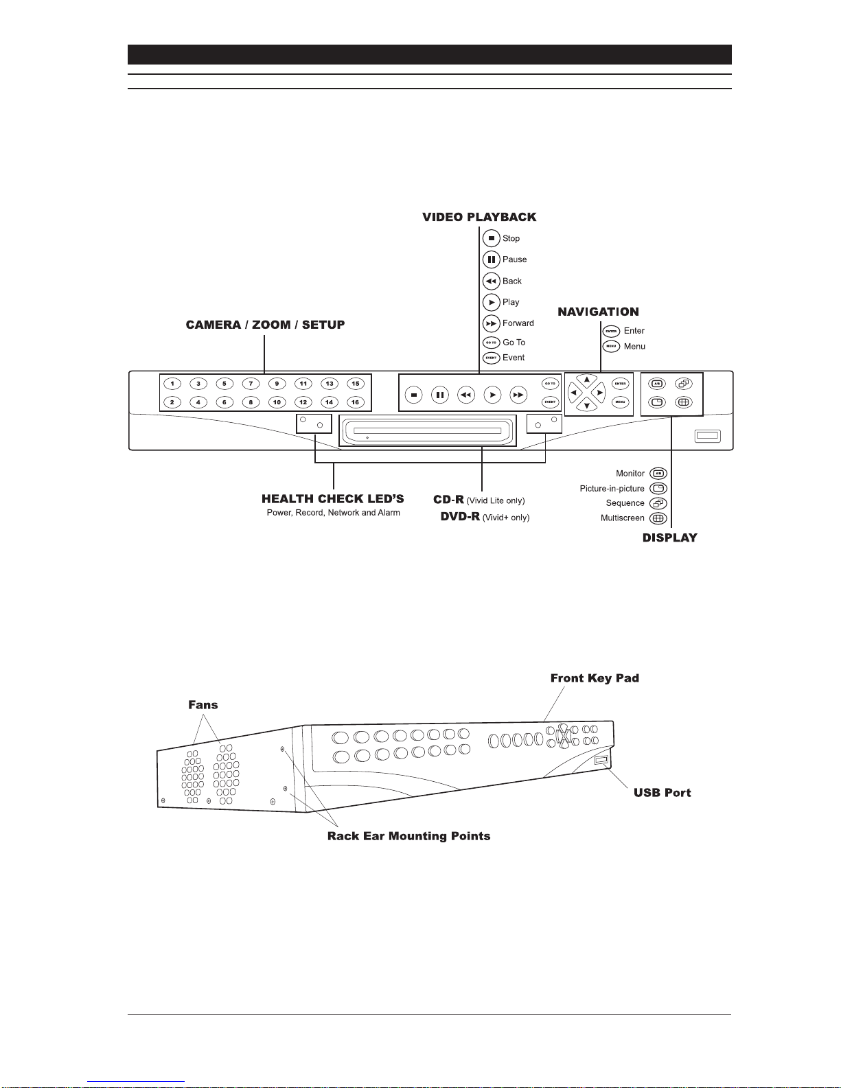
Front Panel Layout .................................................................................................................................................. 10
Rear Panel Layout................................................................................................................................................... 11
Installation.................................................................................................................................................................... 12
Installation - step 1 choose a suitable location ....................................................................................................... 12
Installation - Step 2 Install DVR in Final Location ................................................................................................... 13
Installation - Step 3 Connect up DVR...................................................................................................................... 14
Manually Set up Network Connection (Optional) .................................................................................................... 15
Configure Individual Cameras (Optional) ................................................................................................................ 15
Basic System Set up and Operation............................................................................................................................ 16
Menu Access and Navigation .................................................................................................................................. 16
Select Operating Language .................................................................................................................................... 17
Select Date and Time Format ................................................................................................................................. 17
Set Current Date and Time...................................................................................................................................... 17
Basic Functions ........................................................................................................................................................... 18
Selecting a Camera................................................................................................................................................. 18
Digitally zooming a camera ..................................................................................................................................... 18
Selecting a monitor ................................................................................................................................................. 18
Playback.................................................................................................................................................................. 18
Live View ................................................................................................................................................................. 18
Reverse Playback ................................................................................................................................................... 18
Fast forward............................................................................................................................................................. 18
Pause Playback....................................................................................................................................................... 18
Go To ....................................................................................................................................................................... 18
Event ....................................................................................................................................................................... 19
Sequences .............................................................................................................................................................. 20
Picture in picture...................................................................................................................................................... 20
Multiscreen .............................................................................................................................................................. 21
Telemetry ................................................................................................................................................................. 22
System Functions ........................................................................................................................................................ 23
Hardware Setup Menu ............................................................................................................................................ 23
Cameras.................................................................................................................................................................. 23
Disks........................................................................................................................................................................ 26
Relays ..................................................................................................................................................................... 28
Alarms ..................................................................................................................................................................... 28
Networking .............................................................................................................................................................. 30
Configure Display ........................................................................................................................................................ 32
Alarm Status................................................................................................................................................................. 34
Recording Setup .......................................................................................................................................................... 35
Replay.......................................................................................................................................................................... 38
General ........................................................................................................................................................................ 40

Baxall Vivid Digital Video Recorder User Manual
4
CONTENTS
Appendix 1 - Main I/O Connector Pin Out.................................................................................................................... 43
Appendix 2 - Baxnet Keyboard connections................................................................................................................ 44
Appendix 3 - Baxnet Keyboard and Dome Camera connections ................................................................................ 45
Appendix 4 - ZKX.. Keyboard Mapping........................................................................................................................ 46
Appendix 5 - USB Keyboard Mapping ......................................................................................................................... 47
Appendix 6 - Exporting files to CD and DVD ............................................................................................................... 48
Appendix 7 - Exporting files to a USB Memory stick ................................................................................................... 50
Appendix 8 – System Specification.............................................................................................................................. 52
Appendix 9 - Passwords .............................................................................................................................................. 54

User Manual Baxall Vivid Digital Video Recorder
5
SAFETY SYMBOLS
The following symbols are used in this manual:
An exclamation mark within a triangle, indicates an important installation, operating or maintenance (service)
instruction. Failure to read and adhere to these instructions may:
• Be potentially hazardous or operationally risky
• Result in equipment failure or incorrect operation
• Possibly invalidate the manufacturers warranty
Alightning flash, within a triangle, indicates that there are un-insulated “dangerous voltages” present that may
be of sufficient magnitude to constitute a risk of electric shock.
Therecyclingsymbol, indicates that anitem mayneed proper disposalor recyclingin accordance withapplicable
local government, state or federal laws.
IMPORTANT SAFETY NOTICES
Attention:The VividDVRisaprofessionalpieceofequipmentthatis designed for use within a commercial environment
for general security and surveillance applications. Installation and service should be performed by suitably qualified
personnel only in accordance with local government, state or federal laws.
Power disconnect: The Vivid DVR has no “on/off” switch. Power is disconnected by switching off the supply to the
Vivid DVR’s external power supply unit (PSU) at the mains electrical supply socket and removing the DC power cord
fromthe back of the Vivid. Forthis reason, themains electricalsupply socket shouldbe closeto, andeasily accessible
from the Vivid DVR.
Warning: To reduce the risk of fire or shock, do not expose the Vivid DVR or its PSU to rain or moisture.
Vivid DVR instructions: Read and comply with all the safety, installation and operating instructions for the Vivid
DVR when installing and operating your new system.
Keep all the safety, installation and operating instructions supplied with the Vivid DVR for future reference.
If you are unsure about any aspect of the instructions supplied with the Vivid DVR, please contact your local Baxall
distributor, dealer or installer before proceeding to install, set-up or use the system.
Other equipment instructions: The Vivid DVR cannot be installed and operated without being connected to other
equipment within a complete CCTV system, such as cameras and monitors. Read and comply with all the safety,
installation and operating instructions for the equipment you intend to connect your Vivid DVR to when installing and
operating your system.
If you are unsure about any aspect of the instructions supplied with the equipment you intend to connect to your Vivid
DVR, please contact your supplier.
Ventilation: To avoid the risk of overheating and a reduction in the operating life of the Vivid DVR, ensure that no
ventilation openings in the system are blocked and that the installation instructions contained in this document are
adhered to.
Do not install the Vivid DVR near any heat sources such as radiators or hot air ducts.
Lifting and handling: The Vivid DVR is heavy and may cause injury if incorrectly lifted or handled. Always follow
your local Health and Safety or OSHA guidelines when lifting the Vivid DVR from its package or installing the unit.
Rough handling: The Vivid DVR contains hard disk drives. These are sensitive to shock and easily damaged –
especiallywhen the system ispowered up. Roughhandling orsharp shocksto thesystem, whetherduring installation
or during system use, may damage the hard disk drives and possibly invalidate the system warranty.
Electrostatic-sensitive device: During installation, and especially if working inside the Vivid DVR’s chassis, always
use proper antistatic precautions, including correctly fitted wrist straps, to avoid damage to the Vivid DVR or its
internal electronics from unintentional electrostatic discharge.

Baxall Vivid Digital Video Recorder User Manual
6
IMPORTANT SAFETY NOTICES
Fast Transients and Surge: regardless of the inbuilt protections of the Vivid DVR, Baxall Ltd recommend that
appropriate fast transient and surge protection is fitted to all vulnerable cables, such as video and Ethernet cables
and that other cables, such as s-video cables, SCSI cables, etc., are kept to lengths of less than 3m to minimise risk
of damage to the Vivid DVR or loss of valuable video data.
All installations: Baxall Ltd strongly recommend that for all installations – especially those that may be security
critical, or that are in areas subject to surges, dips, or interruptions in the mains electrical power supply – that a
suitable uninterruptible power supply (UPS) is used to condition and protect the Vivid DVR and its peripherals.
Warning: The primary purpose of this product is to digitise, compress, record and playback CCTV video. The other
secondary features of this product, such as motion detection, alarm handling and audio recording, are provided for
convenience and should not be relied upon as the primary means of meeting requirements for these functions in an
installation.
Lithium battery: The Vivid DVR contains a replaceable lithium battery. This battery must only be replaced by a
suitably qualified service engineer with the same type as originally fitted to the system.
After removal the original battery must be disposed of or recycled in accordance with local government, state or
federal laws.
Warning: Risk of explosion. Do not incinerate the replaceable lithium battery in the Vivid DVR.
REGULATORY NOTICES
FCC (USA Only)
This device complies with part 15 of the FCC Rules. Operation is subject to the following two conditions: (1) This device may
not cause harmful interference, and (2) this device must accept any interference received, including interference that may
cause undesired operation.
This equipment has been tested and found to comply with the limits for a Class A digital device, pursuant to part 15 of the
FCC Rules. These limits are designed to provide reasonable protection against harmful interference when the equipment is
operated in a commercial environment. This equipment generates, uses, and can radiate radio frequency energy and, if not
installedandusedinaccordancewiththeinstruction manual, may cause harmful interference to radio communications. Operation
of this equipment in a residential area is likely to cause harmful interference in which case the user will be required to correct
the interference at their own expense.
Modifications not expressly approved by the manufacturer could void the user’s authority to operate the equipment under FCC
rules.
CE Mark (EU Only)
The manufacturer declares that the product supplied is compliant with the provisions of the EMC Directive 89/336 EEC, the
Low Voltage Directive 72/23 EEC and the CE marking directive 93/68 EEC and associated amendments. A “Declaration of
Conformity” in accordance with the above directives is held on file at Baxall Limited, Stockport SK6 2SU, England. A copy of
which is available upon request.
This is a ClassAproduct. In a domestic environment this product may cause radio interference, in which case the user may be
required to take adequate measures.
UNPACKING
Check you have the following items included in the Vivid DVR package:
• Vivid DVR
• External power supply unit, with integral 12V power cord
• IEC electrical mains power cord
• 2 rack mounting brackets
• Vivid DVR User manual
• Vivid DVR PC Remote Viewing Software (on CD-ROM)

User Manual Baxall Vivid Digital Video Recorder
7
INTRODUCTION
Welcome to the Vivid DVR User manual. This manual contains all the information you need to install, set up and operate your
Vivid DVR.
Read and Retain Safety Notices
Read and retain for future reference the Vivid DVR Safety Notices above. If you are unsure about the meaning of the Safety
Notices or any other aspect of the Vivid DVR User manual, please contact your local distributor, dealer installer or Baxall Ltd for
guidance before proceeding to install, set-up or use the Vivid DVR.
Gather Equipment and Tools
Ensure you have all the other equipment and tools you require for your Vivid DVR installation. For a minimum installation, you
will require:
• At least one PAL or NTSC CCTV surveillance camera and power supply.
• At least one (main) CCTV surveillance monitor and power cord, compatible with the PAL or NTSC surveillance camera
above.
• Suitable coaxial cables to connect the camera to the Vivid DVR and either a coaxial or S-Video cable to connect the Vivid
DVR to the monitor.
• A standard Ethernet cable if the system is to be connected to a network.
Ensure you are familiar with all of the safety and installation requirements of the other equipment you plan to install with your
Vivid DVR before proceeding with the installation process.
Note: Other equipment, typically a TV monitor, may be supported on top of the Vivid DVR – provided the weight of the other
equipment does not exceed 16Kg (35 pounds), the ventilation holes and fans in the side of the Vivid DVR are not obstructed,
and the equipment placed on top of the system is not outside the operating temperature range of the Vivid DVR.
OVERVIEW
The Vivid DVR is a purpose made embedded digital video recorder designed for closed circuit television (CCTV) security and
surveillance applications.
The Vivid DVR combines into a 1½U single 19" rack sized unit the functionality of a:
• Video multiplexer,
• Digital video recorder,
• Network video server.
Key features of all Vivid DVRs include:
• Powerful embedded 32bit RISC for purpose made performance and functionality.
• JPEG2000 image compression for high quality picture recording and advanced image compression features.
• Up to two internal ATA hard disk drives and SCSI-2 i/o for market leading video storage capability.
• USB 2 for convenient connectivity to standard PC USB keyboards, USB CD-RW or DVD-RW devices and USB memory
sticks.
• Frontkey pad(or external USB keyboardor remotekeyboard) controlof marketleading domesfor lowcost PTZintegration.
• Fast (100bT) Ethernet with TCP/IP support, network viewing software and SNMP network management for advanced
network video replay, integration and management capabilities.
• Linux operating system for reliable 24/7 operation and the ability to support 3rd party developed value-added applications.
In addition, all Vivid DVRs feature a comprehensive CCTV specification, including:
• Motion detection.
• 16 alarm inputs and 2 relay outputs.
• Protected event recording and logs.
• E-mail event alerts.
• RS232 text recording.
• Single channel audio recording.
• Remote (PC) viewing software (with suitable PC).
• BaxNet remote keyboard support.

Baxall Vivid Digital Video Recorder User Manual
8
VERSIONS
Features
VIVID Lite VIVID VIVID+
Record speed 25pps 50pps 50pps + TURBO*
Mode Duplex Triplex Triplex
Internal Writer CD No DVD
Alarms Yes Yes Yes
SVHS Monitor No Yes Yes
Audio No Yes Yes
SCSII No Yes Yes
Front panel USB Yes Yes Yes
BaxNet Yes Yes Yes
Dome Control Yes Yes Yes
Ethernet Yes Yes Yes
*In TURBO mode the VIVID+ unit will record at a rate of 100pps at half image resolution
Product codes
VIVIDLite 6/80 DVR, Duplex, CD, 6 channel, 80Gb hard drive
VIVIDLite 6/320 DVR, Duplex, CD, 6 channel, 320Gb hard drive
VIVIDLite 10/160 DVR, Duplex, CD, 10 channel, 160Gb hard drive
VIVIDLite 10/320 DVR, Duplex, CD, 10 channel, 320Gb hard drive
VIVIDLite 16/160 DVR, Duplex, CD, 16 channel, 160Gb hard drive
VIVIDLite 16/320 DVR, Duplex, CD, 16 channel, 320Gb hard drive
VIVIDLite 16/600 DVR, Duplex, CD, 16 channel, 600Gb hard drive
VIVID 6/80 DVR, Triplex, 6 channel, 80Gb hard drive
VIVID 6/320 DVR, Triplex, 6 channel, 320Gb hard drive
VIVID 10/160 DVR, Triplex, 10 channel, 160Gb hard drive
VIVID 10/320 DVR, Triplex, 10 channel, 320Gb hard drive
VIVID 10/500 DVR, Triplex, 10 channel, 50Gb hard drive
VIVID 16/160 DVR, Triplex, 16 channel, 160Gb hard drive
VIVID 16/320 DVR, Triplex, 16 channel, 320Gb hard drive
VIVID 16/600 DVR, Triplex, 16 channel, 600Gb hard drive
VIVID 16/1000 DVR, Triplex, 16 channel, 1Tb hard drive
VIVID+ 6/80 DVR, Triplex, DVD, 6 channel, 80Gb hard drive
VIVID+ 6/320 DVR, Triplex, DVD, 6 channel, 320Gb hard drive
VIVID+ 10/160 DVR, Triplex, DVD, 10 channel, 160Gb hard drive
VIVID+ 10/320 DVR, Triplex, DVD, 10 channel, 320Gb hard drive
VIVID+ 10/500 DVR, Triplex, DVD, 10 channel, 500Gb hard drive
VIVID+ 16/160 DVR, Triplex, DVD, 16 channel, 160Gb hard drive
VIVID+ 16/320 DVR, Triplex, DVD, 16 channel, 320Gb hard drive
VIVID+ 16/600 DVR, Triplex, DVD, 16 channel, 600Gb hard drive
VIVID+ 16/1000 DVR, Triplex, DVD, 16 channel, 1Tb hard drive

User Manual Baxall Vivid Digital Video Recorder
9
SYSTEM LAYOUT
The Vivid DVR consists of a 1 1/2 U 19 inch rack mount unit that is 44cm (17 inches) wide and 37cm (14 inches) deep that
weighsapproximately 5Kg (11 pounds) with asingledisk drive fitted. Thesystem hasarobust all-metal enclosure with aplastic
moulded front panel which contains a rubber membrane key pad and a USB 2 port – all other I/O and power ports are located
on the rear panel of the unit. The sides of the Vivid DVR feature rack ear mounting points on both sides, ventilation input vents
on the right and fan exhaust vents on the left:
Figure 1 Front Left View Vivid DVR
Optional rack ears are supplied with the unit for rack-mounted installations, and stick on rubber feet are supplied for desktop
applications.

Baxall Vivid Digital Video Recorder User Manual
10
FRONT PANEL LAYOUT
The function of these keys is straightforward:
Camera / Zoom / Setup Keys
The camera/zoom/setup keys allow you to:
• Select which camera is displayed on the monitor,
• Digitally zoom a specific camera view, by double pressing the relevant camera key.
• Enter the setup menu for a specific camera, by pressing and holding the relevant camera key.
The camera keys are also used to enter numbers in the menu system and to set and activate PTZ presets, when the Vivid DVR
is in PTZ control mode.
Video Playback Keys
The video playback keys allow you to control the replay of recorded video:
• The GO TO key calls up a date and time entry screen, which allows you to go to a specified date and time and replay any
video recorded.
• The EVENT key calls up a list of saved system, motion detection or alarm events (depending on the setup of the unit),
which can then be selected and replayed,
• The Play, Rewind, Fast forward and Pause keys, which function like the keys on a VCR. In particular, the play and
rewind and fast forward keys allow you to instantly replay recorded video for whichever camera is currently viewed or
selected.
• The STOP/LIVE button, which stops the replay of recorded video and returns the display to live video.
The GO TO and ENTER keys also double up as the zoom in and zoom out keys, when the Vivid DVR is in PTZ control.
Navigation Keys
The navigation keys consist of:
• Four arrow keys, which are used for navigate between camera windows in multi-screen mode and for navigating through
the Vivid DVR menu.
When navigating menus:
• The up and down arrow keys are used for moving up and down menu lists to highlight the required item, and also for
increasing or decreasing values in text and number input boxes.
• The left and right arrow keys are used for moving up and down between menu levels, and also, in the case of the right
arrow key, for selecting highlighted menu options.
The arrow keys also provide tilt up, tilt down, pan left, pan right functions, when the Vivid DVR is in PTZ control mode.
• The ENTER key, which is used to select menu options from drop down lists, or to confirm numbers or text entered with the
arrow keys. The ENTER key is also used to select the active camera in multi-screen mode, or, when followed by a press
of the MON A/B key, to activate telemetry and control selected PTZ cameras.
• The MENU key, which is used to enter or leave the Vivid DVR menu system.
The ENTER and MENU keys also double up as the focus near, focus far keys, when the Vivid DVR is in PTZ control mode.
Display Keys
The display keys, which control the selection and display of cameras on the monitors and consist of:
• The MON A/B, which switches the active display between the MAIN and the SPOT monitor.
This key is also used in combination with the ENTER key – see above – to activate PTZ control mode on a selected, active
camera
• The PIP key, which activates a picture in picture display, and also changes the size of the PIP window. Repeat pressing
also changes the position of the PIP display on the monitor.
• The SEQ key, which activates the display to sequence between all the cameras enabled on the system.
• The MULTI key, which toggles the display through the various multiscreen displays offered by the Vivid DVR.
Other Front Panel Features
Health Check LEDs –Thefront panel features fourLEDs,located below the videoplaybackkeys. These LEDs provide aquick
overview of the health of your Vivid DVR. They consist of:
• Three blue LEDS, which, from left to right, indicate that the system is correctly powered, recording video, and connected
to a working network.
• One blue LED, which is lit whenever an alarm event is detected or a system malfunction condition exists.
USB 2.0 Port – Mounted in the lower right hand side of the front panel, below the “display” keys, the Vivid DVR features a
convenient ‘plug & play’ USB 2.0 port, which can be used for connecting a variety of useful devices, including:
• CD rewriters
• USB memory sticks
• PC keyboards
• DVD-Rom writers/re-writers

User Manual Baxall Vivid Digital Video Recorder
11
REAR PANEL LAYOUT
The back panel of the Vivid DVR provides a wide variety of input and output (I/O) ports to enable you to make the most of your
system.
Working from left to right and top to bottom, as you look at the back of the system, the Vivid DVR I/O ports consist of:
1. 26-way terminal block. Used with the screw terminal plugs supplied, this block provides easy and convenient connections
for:
• 16 alarm input terminals
• 4 relay output terminals
• 1 two-wire RS485 terminal
• 4 grounds
2. 9-pin RS232 port, which is fully configurable from the Vivid DVR menu system.
3. S-Video output for the main monitor display (VIVID and VIVID+ only)
4. Three 3.5mm audio connectors for single channel audio recording (VIVID and VIVID+ only), including:
• MIC In
• Line In
• Line Out
5. 12VDC input socket.
6. RJ45 10/100 base T Ethernet connector, for Fast Ethernet communications.
7. A 50 pin high density SCSI connector, for connection to up to 3 daisy-chained RAID devices (VIVID and VIVID+ only).
8. Stacked dual port RJ45 RS485 connector, which can be used, like the two wire connection on the terminal block, for PTZ
control, or for daisy-chaining RS485 devices using Baxnet.
Note: This is a single logical RS485 I/O port on to the Vivid DVR.
9. MON A, main monitor, and MON B, SPOT monitor, analogue video output BNC connectors.
10. Analogue video input/output BNC connectors for connecting CCTV surveillance cameras to the Vivid DVR:
• The top row of connectors is for the camera input connection.
• The bottom row of connectors is to provide a loop-through output capability so the camera signals can be passed to other
possible devices in the installation.
These connectors are software terminated and un-terminated as required from the Vivid DVR menu system.
Camera numbering is in sequence from left to right, as you look at the rear of the Vivid DVR.
11. Earthing point. Use of this Earth point is strongly recommended.

Baxall Vivid Digital Video Recorder User Manual
12
INSTALLATION - STEP 1 CHOOSE A SUITABLE LOCATION
Introduction
The Vivid DVR design is robust, has a wide temperature and humidity operating range, and has been independently tested to
comply with the demanding system immunity requirements (ESD, Fast Transients, Surge and Radiated Immunity) of the
European standard for Electronic Security Systems, EN50130-4.
Nevertheless, locating the Vivid DVR in a controlled or benign environment, such as in an equipment rack in a server room
(ideally) or an air-conditioned office, and paying careful attention to the following issues will minimise the possibility of in-use
equipment failures – with the possible consequent loss of important data - and maximise the operating life of your new Vivid
DVR.
Moisture
To avoid shock hazards or the risk of fire ensure that the Vivid DVR is not installed anywhere that it will be exposed to rain or
moisture.
Temperature
The Vivid DVR has a specified operating temperature range of 0°C to 40°C (32°F to 104°F).
However, like all computer equipment, an ambient temperature range of 21°C to 23°C (70°F to 74°F) is optimal for long-term
system reliability. Atemperature level near 22°C (72°F) is also desirable because it makes it easier to maintain a safe relative
humidity level (see below). This recommended temperature also provides an operational buffer in case the environmental
support systems, such as air conditioning, malfunction.
Note: The operating temperature range for the Vivid DVR applies to the air taken in by each Vivid DVR at the point where the
air enters the system – and not necessarily the ambient temperature in the room where the system is installed. To check the
temperature of the air entering the Vivid, measure the temperature at 5cm (2 inches) from the right side of the equipment.
Caution: For maximum reliability please ensure that the Vivid DVR is not placed next to a source of excessive heat, such as
a radiator, hot equipment, or hot air duct or exhaust vent.
Humidity
The Vivid DVR has a specified operating range of 20% to 90%, non-condensing, relative humidity (RH).
However, like all computer equipment, an ambient relative humidity level between 45% and 50% is most suitable for long term
system reliability.
The main reason for this is that the amount of moisture that air can hold is temperature dependent. Therefore, if the relative
humidity is at either extreme of the safe operating range of the equipment, relatively small changes in ambient temperature can
easily result in the relative humidity moving outside the operating limits of the system.
In the case of very high relative humidity, a small reduction in temperature may lead to moisture condensing on the system –
possibly causing long term system damage through corrosion.
At the other extreme, low temperatures and low relative humidity, a small temperature increase may result in an unacceptably
low relative humidity leading to a greatly increased risk of intermittent interference, and even possible system damage, from
electrostatic discharge (ESD). This is especially true for relative humidity levels below 35%.
Operating the equipment in a relative humidity range of 45% to 50% minimises the risk of the above problems and ensures the
widest margin of time to fix a problem in the event of an environmental system failure.
Environmental Stability
Formaximum long-term systemreliability, environmental conditions shouldnotbe allowed tochange bymorethat 5.5°C (10°F)
or 10% relative humidity in an hour.
Ventilation and Cooling
The Vivid DVR draws in ambient air for cooling from the right and discharges heated exhaust air to the left of the system (when
looked at from the front). Ensure that the air vents on either side of the system are not obstructed. In particular, ensure that
there are no obstructions within 5cm (2 inches) of either side of the system.
When installing the Vivid DVR in an equipment rack within a server room, take care to ensure that the heat output of the Vivid
DVR (listed in the specifications section at the back of this manual) is taken fully into account when calculating the cooling
requirements of the server room and that there is an adequate flow of cooled air to the system.
Note: In all installations, ensure that the cool air intake vents on the right side of the system are not close to the hot air exhaust
vents of any other system.
Environmental Acclimatisation
Prior to installing and powering up the Vivid DVR you should compare the temperature and humidity of the environment in
which the system had been stored to the conditions in the location where the unit is to be eventually installed.
Electronicequipment can bedamagedif the
rate
oftemperature or humiditychange thatitis exposed tois toogreat- especially
when power is applied to the system. The maximum positive or negative temperature gradient that is recommended for
multilayered printed circuit boards is approximately 2°C (4°F) per hour. The same applies to humidity; it is best for change to
occur slowly.
Therefore, if it is necessary to compensate for significant temperature or humidity differences between the system and the
installation location, place the Vivid DVR, in its shipping packaging, in a location that has a similar temperature and humidity
environment as the eventual location for at least 24 hours before installation to prevent possible damage from thermal shock
and condensation.

User Manual Baxall Vivid Digital Video Recorder
13
INSTALLATION - STEP 1 CHOOSE A SUITABLE LOCATION
Vibration and Shock
The Vivid DVR contains up to two internal hard disk drives. These disk drives are susceptible to damage from excessive shock
and vibration – especially when powered up and in use.
Ensure that the chosen location for the Vivid DVR protects the system from accidental shocks and vibration whilst in use.
Also, ensure the system is properly powered down, and not subjected to rough handling, before any installation, maintenance
or removal activity.
Electrical Power Supply
The effects of power disturbances on sensitive electronic equipment can include data errors, system halts, memory or program
loss, or equipment damage. Further, electronic equipment that is subject to repeated power interruptions or fluctuations can
experience a higher component failure rate than equipment that has a stable power source.
For security critical installations, the power infrastructure should be properly designed – through the use of UPS, backup
generators, and secondary power feeds - to maintain system up time even during disruption of the main power source.
In all installations, using an online uninterruptible power supply (UPS) is a good strategy for obtaining a clean, stable power
source. The online UPS filters, conditions, and regulates the power. It protects the systems from fluctuating voltages, surges
and spikes, and noise that may be on the power line.
The battery backup for the UPS should be capable of maintaining the critical load of the Vivid DVR for a minimum of 30 minutes
during a power failure. After which time, depending on the type of UPS selected, the Vivid DVR can be automatically powered
down in a controlled fashion to protect both the system hardware and the data captured on the hard disks.
In a security critical installation that has been properly constructed, 30 minutes should typically provide sufficient time to allow
for the transfer of power to an alternate feed or to the backup power generator.
Grounding
Aproperly installedVividDVRis grounded through thepowercable. However,additional grounding,using thedesignatedEarth
point on the rear of the chassis helps to protect the system from potential immunity problems, such as ESD and high energy
radiated RF fields. Baxall Ltd recommends the use of this additional grounding facility in all Vivid DVR installations.
Grounding design in the United States should comply with U.S. National Electrical Code unless superseded by local codes. For
international operation, consult the country or local electrical codes.
In all cases, enlist the aid of a qualified electrician to install grounding cables.
Qualified service personnel should always use an antistatic wrist strap when working inside the Vivid DVR chassis.
Physical Security and Fire Protection
Video footage captured by the Vivid DVR may be important evidence. Give consideration when locating the Vivid DVR to its
physical protection from unauthorised access and from fire risks. The ideal location for your Vivid DVR is a controlled server
room location.
INSTALLATION - STEP2 INSTALL DVR IN FINAL LOCATION
Introduction
The Vivid DVR is designed to be used in two basic kinds of location:
1. Rack-mounted in a standard 19 inch electronic equipment rack
2. As a desktop unit.
Lifting and Handling
The Vivid DVR is heavy and may cause injury if incorrectly lifted or handled. Always follow your local Health and Safety or
OSHA guidelines when lifting the Vivid DVR from its package.
Desktop Location
No special precautions or instructions are required for locating the Vivid DVR on to a desktop location – other than to:
• Install the rubber feet (supplied) on to the base of the Vivid DVR to insulate the unit from vibrations and shock
• Observe proper lifting precautions commensurate with the weight and size of the system.
Rack-mount Location
When rack-mounting a Vivid DVR please follow the following instructions:
• Fit the rack ears (supplied) to the front sides of the Vivid DVR.
Caution: All four rack ear mounting points must be used to attach the rack ears to the Vivid DVR and the connecting screws
used to mount the rack ears must be fully tightened into the body of the system.
Warning: Failure to follow this instruction properly may result in possible injury to personnel or damage to the Vivid DVR

Baxall Vivid Digital Video Recorder User Manual
14
INSTALLATION - STEP 2 INSTALL DVR IN FINAL LOCATION
• Consult the appropriate rack-mounting documentation for the rack cabinet being used before attempting to install any
Vivid DVR into a rack,
• Before attempting to install a Vivid into a rack make sure the rack is stable by either fully extending its anti-tip legs (if
mounting the Vivid on a slide-out shelf) or ensuring the rack cabinet is firmly located or attached to the floor,
• Baxall recommend that in all cases the rear or sides of a rack-mounted Vivid DVR should be supported by suitable rack
shelves or supports in addition to the main rack ears at the front of the unit
• In a mixed installation, install the heaviest installation items, such as RAID devices or UPS, in the lowest possible positions
in the rack
• If installing additional Vivid DVRs, install the remaining systems from the lowest system upward into the rack.
Note: Baxall Ltd always recommends that a ½U vertical gap is left between rack-mounted equipment.
INSTALLATION - STEP 3 CONNECT UP DVR
Connect Cameras
Connect a coaxial cable to the video output BNC connector of the CCTV camera. Connect the other end of the coaxial cable
to the top row camera 1 video input BNC connector on the Vivid DVR. The lower connector is a loop-through connector for
connecting the video signal from the camera through to other equipment.
Depending on the model of Vivid DVR ordered, up to 6, 10 or 16 CCTV cameras can be connected to a single Vivid DVR.
Connect Main Monitor
Connect the Vivid DVR to the main monitor. This can be achieved by either using an S-Video cable to connect the Vivid DVR
to the S-Video input on the monitor, or by using a coaxial cable to connect the MONAvideo output BNC connector on the Vivid
to a video input BNC connector on the monitor.
The MON B video output connector is used for connecting a second SPOT monitor to the Vivid DVR, if required.
Connect Cameras and Main Monitor to Power Supply
Connect the CCTV cameras and main monitor to the power supply, in accordance with the manufacturers instructions.
Ensure the CCTV cameras and main monitor are powered up before powering up the Vivid DVR.
Connect to Network
Connect one end of the Ethernet cable into the Ethernet port on the Vivid DVR and the other into a local Ethernet network port.
Note: Contact your IT/IS department for advice on which external network port to use and also to ask if the local network will
provide an IP address automatically, using DHCP, or whether the IP address of the Vivid needs to be configured manually? In
the latter case, ask them to provide you with details of all the IP addresses you will need later on in the installation process.
Make a note of the numbers they provide you with here:
• Mandatory information for manual network set up:
• Optional information for manual network set up:
Connect DVR to Power Supply
Plug the Vivid DVR external power supply into the 12 Volts socket on the back of the unit. Connect the power cord supplied into
the external power supply and plug the power cord into your mains power source or UPS (recommended).
The Vivid DVR will now commence its power up and self-test routines:
• On power up, the Vivid DVR will momentarily sound its alarm buzzer.
• The fans and disk drives will power up and the green power LED on the front panel will light up.
• After about one minute the monitor screen will momentarily display the Vivid DVR welcome screen and, if a camera is
connected to the camera 1 video input BNC, the Vivid DVR will then display a full screen live image from camera 1.
• Finally, the blue recording LED on the front panel will light up, to confirm the unit is recording. Also, if DHCP is in use, the
blue network LED on the front panel will light up to indicate that the Vivid is connected to the local network.

User Manual Baxall Vivid Digital Video Recorder
15
INSTALLATION COMPLETE
At this point, the Vivid DVR will be in the following default configuration:
•All cameras detected at power up will be enabled, viewable and recording at a default rate picture rate and recorded
image size dependant on the the Quick Start menu settings, and an image file size per camera of 24KB,
•Camera 1 will be displayed on the main monitor.
•The system will be available for viewing over the network using the Vivid DVR remote Viewer software supplied
separately with the unit.
MANUALLY SET UP NETWORK CONNECTION (OPTIONAL)
This step only applies if DHCP is not being used and the Vivid DVR network connection needs to be configured manually.
Otherwise, skip to Configure Individual Cameras.
1. Press the menu key to re-enter the Vivid menu system. The Hardware setup option will be highlighted and this should be
selected by pressing the enter key.
2. Navigate down to the networking option using the down arrow key, then select the highlighted Networking option by
pressing the enter key (note that the Ethetnet option needs to be enabled before the following options are visible).
3. Navigate down to the Use DHCP option using the down arrow key and, once it is highlighted, select this option using the
right arrow key. A drop down list will be displayed, use the arrow keys to select the No option and press enter (No is the
default setting).
4. Navigatedown the Networking menudisplayusing the down arrowkeyuntil the IP addressesoption is highlighted,press
the right arrow key to select this option.
5. Using the information you previously recorded in section 3, use the arrow keys to navigate to and select each IP address
that needs to be set in turn.
6. When the address you want to enter is highlighted press the right arrow key. This brings up the input box for each address.
7. Use the right arrow to move along the address and the up and down arrow keys to increase or decrease the numbers until
the correct address is displayed. Alternatively, the camera number keys (1 to 9) can be used to enter numbers.
8. When you have correctly entered an address press the enter key to confirm it. This will close the address input box.
9. Usethe up anddownarrow keys to highlightthenext address andso onuntilall the requiredaddresses arecorrectlyinput.
10. When all the addresses are complete press the menu key to exit the Vivid DVR menu system.
CONFIGURE INDIVIDUAL CAMERAS (OPTIONAL)
If required you can alter the picture size (quality) and record rate for each individual camera you have connected to the Vivid
DVR.
The easiest way to do this is to press and hold the camera key of the camera you want to configure. After entering the
password, this will take you to the camera recording menu for the camera concerned.
Picture Size (Image Quality)
1. To set the picture size, press the down arrow until the picture size option is highlighted and press the enter key to enter
edit mode.
2. Use the up/down arrow keys to either increase the file size (improve recorded picture quality) or reduce the file size
(decrease the recorded picture quality).
3. Press the enter key once you have selected the file size required.
Note: Larger image file sizes take up more hard disk space, so your system will record better pictures but for less elapsed time.
Smaller image sizes take up less hard disk space, so your system will record reduced quality pictures but for a longer time.
Recording Rate
1. To set the record rate, after you have set the image file size, use the arrow keys to highlight Normal pics/sec for Daytime
recording.
2. Once highlighted, press the enter key.
3. Press the up/down arrow keys to increase or decrease the record rate and press the enter key when the correct rate is
selected.
Notes:Ahigher record rate generates more pictures to save to hard disk. Therefore, a higher record rate will provide pictures
at more frequent intervals but reduce the elapsed time for which the system can record.
The Vivid DVR is a multiplexed system. In other words its total maximum record rate of 50pps (PAL) and 60pp (NTSC) for a
720x240 image have to be shared between the various cameras on the system.
Finally
When you have finished setting the image file size and the record rate for the camera selected, select Next page. Repeat for
the next camera as required until all the cameras you wish to individually set up have been configured.
Once you have finished adjusting the image file size, the recording menu will give you an estimate, based on image size,
record rate, hard disk size and other system parameters, of the elapsed time for which your system will record with those
settings.

Baxall Vivid Digital Video Recorder User Manual
16
CONFIGURE INDIVIDUAL CAMERAS (OPTIONAL)
Setting image file size and record rate is a practical compromise between picture quality and pictures per second versus
available hard disk space and the time for which the system can record.
Experiment with the settings of your Vivid DVR to achieve the best picture quality and recording rate for your application needs.
Press the enter key to exit the Vivid DVR menu system.
Congratulations, you have now completed the basic installation and set up of your Vivid DVR. Please take time to get familiar
with the basic operation of your new system before accessing and setting up the advanced features of your Vivid DVR. If you
need to access, more advanced system functions please see the next sections for details.
For require further detail on any aspect of your Vivid DVR please refer, in this order, to:
• Your local Baxall Ltd distributor, dealer or installer,
• The Baxall on-line support pages at www.baxall.com/vivid, or
• Baxall Ltd technical support on: +44 (0)161 406 6611.
BASIC SYSTEM SET UP AND OPERATION
To complete the setup of a basic system configuration access the Vivid DVR menu system and:
• Select the operating language of the system,
• Choose the preferred time and data format,
• Set the local system time and date.
If DHCP is not in use on the local network, it will also be necessary to use the IP addresses you have already obtained from
your IT/IS department and recorded in Step 3 to manually set up the Vivid DVR network access.
MENU ACCESS AND NAVIGATION
To access the menu system, press the menu button, enter the password and then navigate through the menus displayed on
the main monitor using the up, down, left and right navigation keys on the Vivid DVR.
Note: The menu system will time out after a default period of 90 seconds inactivity. This can be altered if required at a later
stage through the General menu display.
MENU HIERARCHY
Hardware setup
Configure display
Alarm status
Recording setup
Replay
General
Main monitor
Spot monitor
Schedule
Motion detection
Sound
RS232 Data
Cameras
Disks
Relays
Alarms
Networking
Displays current alarm status
Displays current motion detection status
{

User Manual Baxall Vivid Digital Video Recorder
17
SELECT OPERATING LANGUAGE
1. Access the Vivid DVR menu system by pressing the menu key and entering the installer password. The top-level menu
window is displayed on the main monitor.
2. Press the down arrow key until the General option is highlighted.
3. Press the enter key. The General menu window is displayed.
4. Press the down arrow key until the Language option is highlighted.
5. Press the enter key. A drop down list opens, displaying all the available language options.
6. Press the down arrow key until the required language option is highlighted.
7. Press enter. The required language option is selected. The drop down list is closed – the menus are now displayed in the
selected language – and you remain in the General menu window.
SELECT DATE AND TIME FORMAT
1. Access the Vivid DVR menu system by pressing the menu key and entering the installer password. The top-level menu
window is displayed on the main monitor.
2. Press the down arrow key until the General option is highlighted.
3. Press the enter key. The Date and Time menu window is displayed.
4. Press the down arrow key to highlight the Date format option.
5. Press the enter key a drop down list appears displaying all the available date format options.
6. Press the down arrow key until the required format is highlighted.
7. Press enter. The required date and time format is selected. The drop down list is closed and you are returned to the Date
and Time menu window.
Note: More advanced time options, such as using an RS485, NTP or GPS time source, along with a discussion of how summer
time settings are handled by the Vivid DVR are covered later in this manual.
SET CURRENT DATE AND TIME
1. Access the Vivid DVR menu system by pressing the menu key and entering the installer password. The top-level menu
window is displayed on the main monitor.
2. Press the down arrow key until the General option is highlighted.
3. Press the enter key. The Date and Time menu window is displayed.
4. Highlight the Date and Time option. Press the right arrow key. The Date and Time input box is displayed.
5. Press the right arrow key to move along the Date and Time input box, using the up and down arrow keys at each point to
increase or decrease the number displayed.
6. When the correct date and time has been entered, press the enter key to implement the new date and time. The Date and
Time input box closes.
Press the menu key to exit the Vivid DVR menu system.

Baxall Vivid Digital Video Recorder User Manual
18
BASIC FUNCTIONS
This section covers basic user functions such as selecting cameras, selecting monitors, etc. A quick reference guide is also
included with the Vivid DVR detailing common operations and functions.
SELECTING A CAMERA
To select a camera for full screen viewing:
1. Press the camera number button corresponding to the camera you want to view.
The selected camera will be shown full screen on the main monitor.
DIGITALLY ZOOMING A CAMERA
Cameras connected to the Vivid DVR can be digitally zoomed by a factor of approximately 2:1. To digitally zoom a camera:
1. Press the camera number button twice in quick succession for the camera you want to zoom.
2. The arrow keys can be used to scroll the image. To return to full screen mode, press the camera number button again.
SELECTING A MONITOR
The Vivid DVR can have two monitors connected to it: a main monitor and a spot monitor. To change the active display:
1. Press the MON A/B key to toggle the active display between the main and spot monitors.
PLAYBACK
To begin playback, press the Play key. Playback will occur at the rate it was recorded. Playback is indicated by a > after the time
display (e,g, 12:00:00>).
LIVE VIEW
To stop playback, press the Stop key. The unit will go into live view mode. Note: Pressing the Stop button stops playback only
- the unit does not stop recording.
REVERSE PLAYBACK
Press the reverse playback key once for normal speed playback. This will be indicated by a < after the time display (e,g,
12:00:00<) Press reverse play again for higher speed playback.This will be indicated by a << after the time display (e,g,
12:00:00<<). Press reverse play again for higher speed reverse playback (indicated by <<< after the time display). Press
reverse play again for high speed reverse playback (indicated by <<<< after the time display).
FAST FORWARD
Press the fast forward key once for fast forward playback. This will be indicated by > after the time display (e,g, 12:00:00>).
Press fast forward again for higher speed fast forward playback (indicated by >> after the time display). Press fast forward
againfor higher speedfast forwardplayback(indicated by >>> afterthe timedisplay). Pressfastforward again for higherspeed
fast forward playback (indicated by >>>> after the time display).
PAUSE PLAYBACK
To pause playback press the pause key. Pressing the pause key again will resume playback
GO TO
The Go To key allows you to select a date and time and play back recorded video. To replay a recorded video from specific time
and date:
1. Press the GO TO key. The Go to... entry window will open.
2. The first field dd (18
in the example above) will be selected. Use the up/down arrow keys (or number keys 1 to 10 where
the number 10 key will enter a ‘0’) to enter the number of the day. Press the right arrow key to select the next field and edit
as above.
3. Continue until the desired date and time have been entered.
4. Press the enter key. The video will be replayed from the selected time and date.
Go to ...
18/04/2005 17:31:57

User Manual Baxall Vivid Digital Video Recorder
19
EVENT
The event key calls up any saved system, alarm or motion detection events which can then be selected and replayed. To select
an event:
1. Press the event key and enter the password. This will open the View events log at the filter page. Use the filter page if
required to filter the event log in order to more easily locate the desired event. Events marked with a X will be passed by
the filter page. For example, to view onlyAlarm type events in the log, clear the X from everything in the Filters list except
Alarm.
2, Using the arrow keys, select View events and press the enter key. The View events page will change to show any saved
events corresponding to the filter criteria entered.
3. Events which can be replayed will have Play in the description line. To play such an event, use the arrow keys to select
play for the event. Press the enter key. The selected event will be played back on the selected monitor.
4. Events can also be deleted by selecting Del, or exported to the designated export device e.g. USB memory stick by
selecting Exp - see Appendix 6 - Exporting Files to CD and DVD.
Filters Alarms [X]
Motion [ ]
Marked blocks [ ]
Video Loss [ ]
Shutdown [ ]
Config change [ ]
Unit password incorrect [ ]
Remote password incorrect [ ]
Exported data [ ]
Cameras 1 2 3 4 5 6 7 8 9 10 11 12 13 14 15 16
[X][X] [X] [X] [X] [X] [X] [X] [X] [X] [X] [X] [X] [X] [X] [X]
View events log
Events with no associated camera [X]
Back to menus View events
Time After time [ ]
Before time [ ]
Showing events 1 - 7 of 7 (Page1/1)
Clear log Return to filters Next page
View events log
Alarm 1 18/04/2005 15:57:20 18/02/2005 15:57:49 Play Del Exp
Alarm 1 18/04/2005 16:31:25 18/02/2005 16:40:51 Play Del Exp
Motion 1 18/04/2005 16:52:21 18/02/2005 16:52:51 Del
Motion 1 18/04/2005 16:54:12 18/02/2005 16:54:42 Del
Motion 1 18/04/2005 16:55:01 18/02/2005 16:55:31 Play Del Exp
Motion 1 19/04/2005 10:51:49 19/02/2005 10:52:18 Play Del Exp
Motion 1 19/04/2005 10:53:21 19/02/2005 10:53:43 Del

Baxall Vivid Digital Video Recorder User Manual
20
SEQUENCES
The Vivid DVR can display all of the cameras connected to it in sequence. Each camera will be displayed on the active monitor
for a period of time set by the Dwell time parameter. To start camera sequencing:
1. Select a camera (sequencing can start from any camera) by pressing the corresponding number key.
2. Press the sequence key.
To stop seqencing:
1. Press the sequence button, or select a camera for full screen viewing by pressing a camera number key.
PICTURE IN PICTURE
The Vivid DVR has a picture-in-picture feature. To activate picture-in-picture (PIP) mode:
1. Press the PIP key.
2. The display will change to the picture-in-picture mode.
To change the size of the PIP:
1. Press the PIP key to change the size of the PIP display. Each press of the PIP key changes the PIPdisplay to one of three
sizes.
To change the position of the PIP display:
1. Use the left/right and up/down arrow keys to move the PIP as shown below.
To change the camera of the PIP display:
To change the camera which is displayed by the PIP, the PIP area of the display (usually referred to as a cameo) needs to be
selected.
1. Press the enter key. This will superimpose a reverse highlighted *on the main camera display (camera 2 in the example
below).
This manual suits for next models
2
Table of contents
Other Baxall DVR manuals